High-level Performance Evaluation of Object Detection based on
Massively Parallel Focal-plane Acceleration Requiring Minimum Pixel
Area Overhead
Eloy Parra-Barrero
1
, Jorge Fern
´
andez-Berni
2
, Fernanda D. V. R. Oliveira
3
, Ricardo Carmona-Gal
´
an
2
and
´
Angel Rodr
´
ıguez-V
´
azquez
2
1
Universidad de Sevilla, 41004, Seville, Spain
2
Instituto de Microelectr
´
onica de Sevilla (IMSE-CNM), CSIC-Universidad de Sevilla, 41092, Seville, Spain
3
Universidade Federal do Rio de Janeiro, 21941-901, Rio de Janeiro, Brazil
Keywords:
Embedded Systems, Vision Pipeline, Early Vision, Smart Image Sensors, Vision Chips, Focal-plane
Processing, Object Detection, Viola-Jones Algorithm, Performance, Processing Acceleration.
Abstract:
Smart CMOS image sensors can leverage the inherent data-level parallelism and regular computational flow of
early vision by incorporating elementary processors at pixel level. However, it comes at the cost of extra area
having a strong impact on the sensor sensitivity, resolution and image quality. In this scenario, the fundamental
challenge is to devise new strategies capable of boosting the performance of the targeted vision pipeline while
minimally affecting the sensing function itself. Such strategies must also feature enough flexibility to accom-
modate particular application requirements. From these high-level specifications, we propose a focal-plane
processing architecture tailored to speed up object detection via the Viola-Jones algorithm. This architecture
is supported by only two extra transistors per pixel and simple peripheral digital circuitry that jointly make up
a massively parallel reconfigurable processing lattice. A performance evaluation of the proposed scheme in
terms of accuracy and acceleration for face detection is reported.
1 INTRODUCTION
Unlike CCD, CMOS technologies do permit the
co-existence of sensing and processing devices on
the same physical substrate. This in turn enables
the incorporation of intelligence at different lev-
els within an image sensor chip (Ohta, 2007). In
terms of computational efficiency and memory ac-
cess saving, the most suitable scheme is focal-plane
sensing-processing (Zar
´
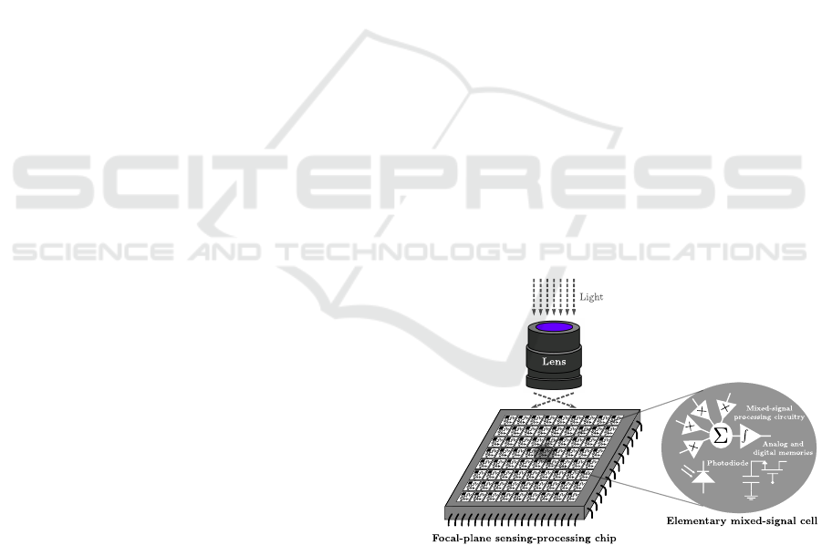
andy, 2011). As shown in
Fig. 1, focal-plane sensing-processing vision chips
feature concurrent image capture and low-level pro-
cessing implemented by an array of interconnected
elementary mixed-signal cells, also known as multi-
functional pixels. This scheme perfectly adapts to
the inherent characteristics of early vision, the most
resource-consuming stage of vision pipelines due to
huge amount of raw information to be handled. The
massively parallel processing and distributed memory
provided by focal-plane lattices can thus achieve a
drastic reduction of memory accesses and a signifi-
cant computing acceleration during this critical stage.
Unfortunately, the incorporation of processing cir-
Figure 1: Sensing-processing vision chips capture and pre-
process images at the focal plane.
cuitry at pixel level has clashing implications on the
other functionality targeted by the chip, image sens-
ing. For a prescribed silicon area—i.e. for a pre-
scribed budget—there is an immediate tradeoff be-
tween the early vision capabilities embedded into the
sensor and the area devoted to capture light per pixel.
Likewise, a greater degree of focal-plane smartness
Parra-Barrero, E., Fernández-Berni, J., Oliveira, F., Carmona-Galán, R. and Rodríguez-Vázquez, Á.
High-level Performance Evaluation of Object Detection based on Massively Parallel Focal-plane Acceleration Requiring Minimum Pixel Area Overhead.
DOI: 10.5220/0005651200790085
In Proceedings of the 11th Joint Conference on Computer Vision, Imaging and Computer Graphics Theory and Applications (VISIGRAPP 2016) - Volume 3: VISAPP, pages 81-87
ISBN: 978-989-758-175-5
Copyright
c
2016 by SCITEPRESS – Science and Technology Publications, Lda. All rights reserved
81
...
...
...
...
...
...
...
...
...
...
...
...
...
...
...
...
...
...
...
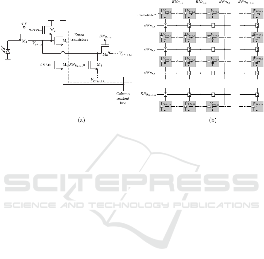
Figure 2: Proposed pixel circuitry (a), and resulting focal-plane processing lattice (b). The signals EN
C
i,i+1
and EN
R
j, j+1
are
driven by the output of corresponding peripheral shift registers.
accomplished by adding more transistors for process-
ing inevitably leads to a reduction of the image reso-
lution since the pixel size increases. Finally, circuits
other than those specifically designed to deal with im-
age capture and readout constitute sources of noise af-
fecting image quality. There is therefore a clear need
for circuit structures capable of maximally exploiting
the advantages of focal-plane processing while mini-
mally affecting the performance of image sensing.
All in all, this paper presents a focal-plane archi-
tecture only requiring two extra transistors per pixel
with respect to the standard 3-T/4-T Active Pixel Sen-
sors (APS) that typically make up commercial CMOS
image sensors (Fowler, 2015). Additional periph-
eral digital circuitry enables reconfigurability. We
describe how the proposed architecture renders pro-
grammable rectangular-wise averaging across multi-
ple image regions in parallel. We then explain why
this pre-processing is useful for feature extraction
acceleration within the Viola-Jones object detection
framework. Lastly, in the context of face detection,
we show how a simple re-design of the first stage
of the classification cascade in conjunction with the
proposed focal-plane pre-processing significantly im-
proves the algorithm throughput with little impact on
the detection performance.
2 FOCAL-PLANE PROCESSING
ARCHITECTURE
A standard 4T APS is depicted in Fig. 2(a) where
two minimum-size transistors have been added to
play the role of switches. These switches intercon-
nect the node holding the pixel voltage with the same
node at neighboring pixels. Their activation is con-
trolled by the corresponding column-wise and row-
wise digital signals denoted by EN
C
i,i+1
and EN
R
j, j+1
,
driven by peripheral shift registers. The resulting
focal-plane processing lattice, once the pixel matrix
has been composed by aggregation of this elemen-
tary cell and removal of unconnected switches at the
edges, is shown in Fig. 2(b). Note that the tran-
sistors exclusively related to the sensing function in
Fig. 2(a), namely M
1−4
, have been eliminated in this
lattice to avoid clutter. The capacitor per pixel repre-
sents the capacitance—parasitic or designed ad-hoc—
associated with the pixel voltage node.
The structure in Fig. 2(b) enables the progres-
sive averaging of rectangular pixel regions in a mas-
sively parallel way. This averaging is carried out by
setting the adequate interconnection patterns through
EN
C
i,i+1
and EN
R
j, j+1
. Thus, when the extra switches
inserted per pixel are set ON, charge redistribution
takes place between the interconnected capacitors.
The final voltage after this redistribution is the same
for all the pixels making up the considered region,
that is, their average value. A key issue concerning
this hardwired computation is that no additional en-
ergy contribution is required apart from the energy
VISAPP 2016 - International Conference on Computer Vision Theory and Applications
82
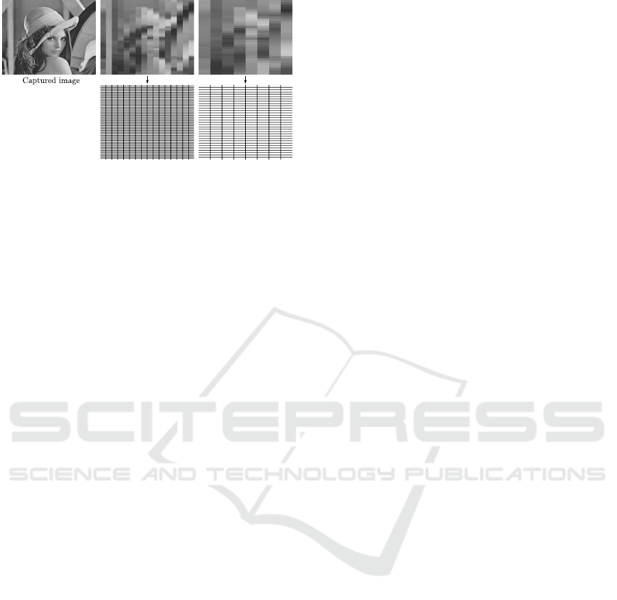
Figure 3: Example of the aggregated pre-processing that
can be provided by the proposed focal-plane architecture.
injected into the pixel matrix during the image cap-
ture reset (Fern
´
andez-Berni et al., 2011). This reset
energy is first partly consumed by photo-transducing
and then by the dynamics of the charge redistribu-
tion, making the whole operation extremely power-
efficient. Subsequent interconnection patterns could
be established in order to obtain new averaging maps
by joining regions averaged just by the previous pat-
tern. This process can continue as requested by the
algorithm exploiting it, as long as the unavoidable
charge leakage across the chip does not exceed a pre-
scribed limit affecting the precision of the computa-
tions. Too many averaging grids could also limit the
frame rate since, after each step—image capture, first
averaging grid, second averaging grid...—a readout
stage must be performed. This is mandatory due to
the destructive nature of the processing taking place
in every grid with respect to the image representa-
tion provided by the previous one. An illustrative
example is depicted in Fig. 3, where two consecu-
tive rectangular averaging grids are applied over the
original Lena image. Note that only one pixel per
rectangle must be readout as all the pixels within a
particular region hold the same value. This signifi-
cantly reduces the number of analog-to-digital con-
versions with respect to the original captured image.
Note also that the rectangles rendered by the second
grid come from grouping regions of 2×2 rectangles
from the first grid and then averaging again, thus de-
stroying the previous representation. For every grid,
all the signals EN
C
i,i+1
and EN
R
j, j+1
are set to logic ‘1’
but those falling at the boundaries between rectangles
that must be set to logic ‘0’, thereby confining charge
redistribution to the desired regions.
3 VIOLA-JONES ALGORITHM
The Viola-Jones sliding window object detector (Vi-
ola and Jones, 2004) is considered a milestone in real-
time generic object recognition. It certainly requires
a cumbersome previous training, demanding a large
number of cropped samples. But once trained, the
detection stage is fast thanks to the computation of
the integral image, an intermediate image representa-
tion speeding up feature extraction, and to a cascade
of classifiers of progressive complexity. Despite its
simplicity and detection effectiveness, the algorithm
still requires a considerable amount of computational
and memory resources in terms of embedded system
affordability. Different approaches have been pro-
posed in the literature in order to increase the perfor-
mance on a limited hardware infrastructure (Camilli
and Kleihorst, 2011; Jia et al., 2012; Ouyang et al.,
2015). In this paper, we describe a new alternative for
the embedded implementation of the algorithm based
on processing acceleration from the very beginning of
the signal chain, the sensing plane itself.
As just mentioned, feature extraction from the in-
tegral image is one of the keys for the success of
the Viola-Jones detector. The so-called Haar-like fea-
tures simply imply contrast comparison of rectangu-
lar pixel regions across the sliding window. Some
examples are shown in Fig. 4. For each feature, a
weighted sum—or average—of the pixels within the
white rectangles is subtracted from a weighted sum—
or average—of the pixels within the black rectangles.
The integral image, obtained in one pass over the
input image, enables the calculation of these sums
by accessing only four of its accumulated pixels in-
stead of massive processing over the original raw pix-
els. Likewise, contrast normalization for detection in
any lighting conditions demands the computation of
the squared integral image. This normalization pre-
cludes any attempt of skipping the computation of
the integral image by directly evaluating the Haar-
like features from averaging grids as proposed in Sec-
tion 2. Furthermore, the large number of features to
be extracted—e.g., over 2000 for the OpenCV (Brad-
ski, 2000) baseline implementation of Viola-Jones
face detection—would require a great deal of focal-
plane grids per captured image, impacting the reach-
able frame rate. Instead, we propose to exploit a re-
duced number of grids to accelerate the first stage of
the classifier. This stage, the most discriminative of
the cascade, is designed to rapidly reject windows
with very low probability of containing the targeted
object. As explained next, it can be re-defined to make
use of the averaging grids while requiring neither the
integral image nor normalization. Note that a first ad-
vantage of this scheme is that the computation of both
integral images, needed in any case for the rest of the
classifier stages, can be carried out in parallel with the
evaluation of the first stage.
High-level Performance Evaluation of Object Detection based on Massively Parallel Focal-plane Acceleration Requiring Minimum Pixel
Area Overhead
83
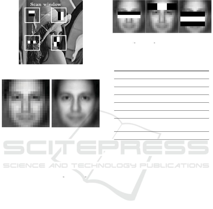
Figure 4: The Haar-like features are evaluated at multiple
locations and scales of the input image.
Figure 5: Generic face: 20×20 pixels (left), 50×50 pixels
(right).
4 RE-DESIGN OF THE FIRST
STAGE
The re-design described next corresponds to the first
stage of the cascade ‘haarcascade frontalface alt.xml’
provided by OpenCV, release 2.4.10 for Windows op-
erating systems. This cascade includes 21 stages and
is defined for a minimum detection size of 20×20
pixels. The Viola-Jones face detector provided by
the same release is our baseline implementation of
the algorithm. As a test bench, we use the Caltech
Frontal Face Dataset (Weber, 1999). It includes 450
frontal face images of 27 people under different light-
ing, expressions and backgrounds with a resolution
of 896×592 pixels in JPEG format. In order to work
with a representative face allowing subsequent extrap-
olation to the rest of the dataset, a ‘generic face’ was
first created. To this end, we ran the algorithm over
the entire dataset. All detected faces were scaled to a
common size and then averaged. The resulting face is
shown in Fig. 5 for two different resolutions.
The three features composing the first stage of the
cascade are depicted in Fig. 6. The evaluation of each
of these features entails the comparison with a spe-
cific threshold coming from the training process that
generated the cascade. There is also a threshold asso-
ciated with the stage itself. For an adequate numerical
Figure 6: Features composing the first stage of the cascade
‘haarcascade frontalface alt.xml’ provided by OpenCV.
Table 1: Checking only the sign of the features instead of
numerical comparison with thresholds leads to a much more
discriminative first stage of the Viola-Jones face detection
algorithm.
Thresholds Only sign
True-positives 445 437
False-positives 7 6
False-negatives 5 13
Precision 98.5% 98.7%
Recall 98.9% 97.1%
Rejected windows
28.9% 66.7%
at first stage
Execution time 86.3s 41.9s
comparison, these thresholds demand the normaliza-
tion of the input image by using the squared integral
image, as previously mentioned. A remarkable first
result stems from removing this threshold analysis
for the first stage. Instead, we simply check the sign
(Abramson et al., 2007) of the three features, only ac-
cepting for further processing those windows where
the three of them produce a positive outcome. Oth-
erwise, the window is rejected. As a result, a much
more discriminative first stage is achieved. Table 1
summarizes the performance of the algorithm when
threshold comparison is carried out and when only
the sign is checked. The detector is configured to
detect faces with a minimum size of 80×80 pixels.
The scale factor for the sliding window is set to the
default value, 1.1. Notably, the values of precision
and recall (Klette, 2014) remain very similar in both
cases but the percentage of rejected windows when
only the sign is checked is significantly larger. The
time required by the algorithm to process the entire
test bench—on an Intel Core i7 at 2.4GHz—is thus
reduced by more than 50%.
Sign checking instead of threshold comparison
therefore permits to skip the computation of the
squared integral image for the first stage of the cas-
cade. We can also get rid of the integral image for
this stage by having the rectangular regions making
up each feature computed from the massively parallel
VISAPP 2016 - International Conference on Computer Vision Theory and Applications
84
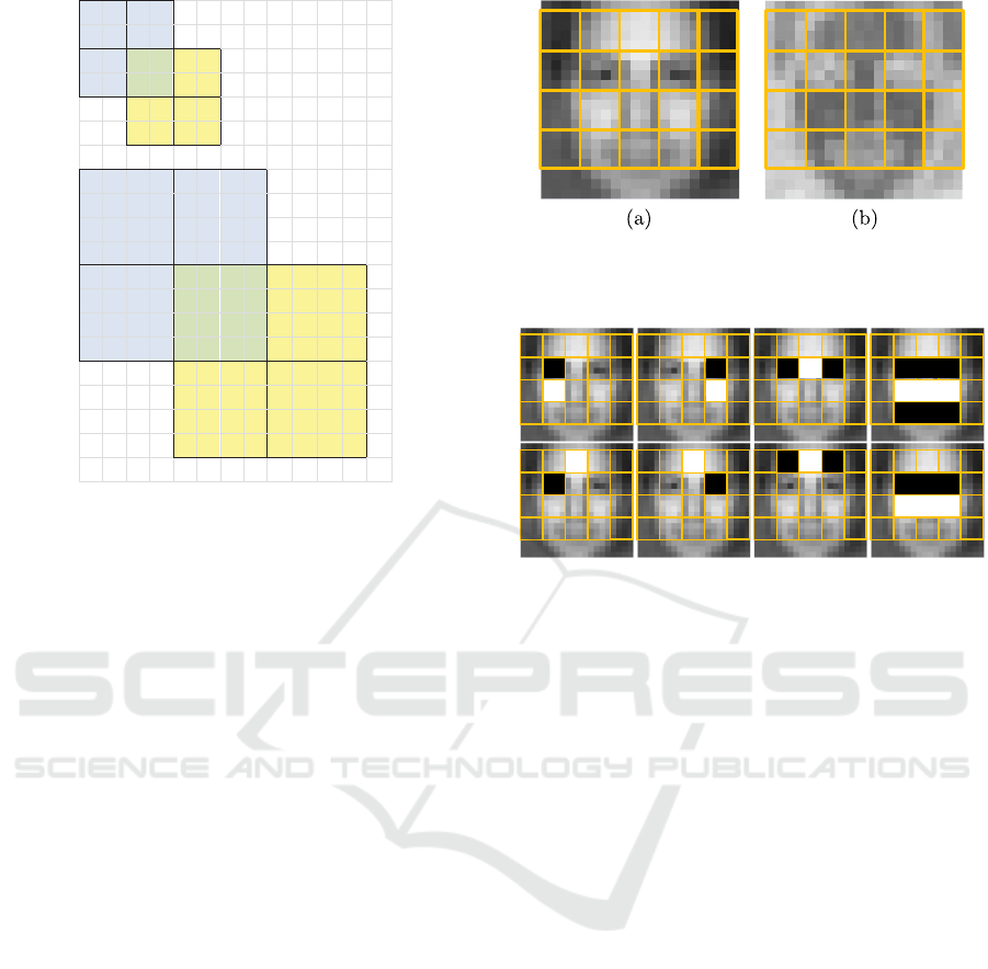
Figure 7: Each focal-plane grid is rendered by grouping
rectangles from the previous one.
focal-plane processing described in Section 2. There
is however a major limitation for this approach due to
the aggregated nature of the operation. Keep in mind
that each grid is always formed by grouping rectan-
gles of the previous one. This forces a minimum step
of scaling and shifting for the sliding window accord-
ing to the elementary rectangle of the first grid. An
example is depicted in Fig. 7. It can be seen that
a first scale featuring a 2×2-px elementary rectangle
necessarily leads to a second scale with a 4×4-px el-
ementary rectangle—we are assuming that both im-
age dimensions are scaled in the same way. Likewise,
the shifting step of the sliding window is 2-pixel for
the first scale and consequently 4-pixel for the second
scale.
In order to overcome this limitation, we propose
the definition of new features for the first stage that
take into account the coarse pixel aggregation at the
focal plane. To this end, we have defined an ele-
mentary grid made up of 4×4-px rectangles over the
‘generic face’, as shown in Fig. 8(a). An estimate of
the most stable regions to define new features over
this grid can be obtained by computing the difference
between the ’generic face’ and each of its constituent
faces detected from the test bench, followed by the
average of the absolute values of these differences.
The normalized result is depicted in Fig. 8(b). Black
indicates no variability at all whereas white repre-
sents maximum variability. We can conclude from
this figure that the nose, forehead and cheek areas
are good candidates for such regions. Conversely,
eyes and mouth present significant variability among
faces. For the eyes, this variability is compensated by
Figure 8: (a) Basic grid defined over the ‘generic face’;
(b) Variability of the ‘generic face’ with respect to its con-
stituent faces detected from the test bench.
Figure 9: Features defining the new first stage of the algo-
rithm over the basic grid.
their usual high contrast with other zones of the face.
All in all, we have carried out a heuristic search of
discriminative features defined over the basic grid in
Fig. 8(a). The resulting features, represented in Fig. 9,
are those which best ranked in terms of highest num-
ber of successful sign checks over the faces detected
when running the baseline algorithm. The perfor-
mance of this baseline implementation when the fea-
tures of the original first stage of the cascade are sub-
stituted for those of Fig. 9 is reported in Table 2. The
detector is configured in the same way as in Table 1
and ran on the same PC. The new features achieve
much greater discrimination while still impacting lit-
tle on the detection performance. The execution time
is decreased by an additional 50% with respect to only
checking the sign of the original features.
5 PERFORMANCE EVALUATION
UNDER CHIP OPERATION
CONDITIONS
The figures in Table 2, while interesting on their own,
do not reflect the targeted real operation conditions
yet. The features were certainly defined according to
the restrictions imposed by the elementary grid, but
the scale factor was still set to 1.1 for comparison
with Table 1. As mentioned in Section 4, such scale
High-level Performance Evaluation of Object Detection based on Massively Parallel Focal-plane Acceleration Requiring Minimum Pixel
Area Overhead
85

Table 2: The new features represented in Fig. 9 achieve even
further discrimination at the first stage with little impact on
the detection performance.
Only sign
(new features)
True-positives 427
False-positives 10
False-negatives 23
Precision 97.7%
Recall 94.9%
Rejected windows
93.7%
at first stage
Execution time 21.0s
factor cannot be provided by the focal-plane acceler-
ation sketched in Fig. 2. The detector must therefore
be configured in order to faithfully emulate the scal-
ing and shifting of the sliding window according to
the scheme in Fig. 7. This implies to scale the in-
put frame following the geometric progression 4 (el-
ementary grid), 8, 16, 32... This scale progression
is depicted in Fig. 10(a) for the Lena image. The
sliding window must also be consequently shifted at
each scale. We must emphasize again at this point
that only one pixel per rectangle needs to be readout.
This is crucial to reduce the speed—and thereby the
power—requirements of an analog-to-digital conver-
sion stage capable of coping with each scale of the
sequence in proper timing. The performance of the
algorithm under these conditions is extremely poor,
as shown along the column ‘Single scaling progres-
sion’ in Table 3. The pixel aggregation is too coarse
for the algorithm to carry out a reliable detection. In
order to circumvent this problem, we must introduce
a second scaling—and shifting—progression, namely
6, 12, 24, 48... This second progression is not com-
patible with the first one for a per-frame processing
owing to the destructive nature of the focal-plane pro-
cessing described in Section 2. Both progressions
must therefore be alternated throughout the input im-
age sequence. Note that this condition assumes slow,
or moderate at most, motion of the targeted object—a
face in this case—across the scene for successful de-
tection. Otherwise, the successive focal-plane grids
applied over one frame would be uncorrelated with
those applied on the next frame. Typical applica-
tions like face recognition—demanding previous face
detection—or automatic camera focus based on face
detection should meet this constraint in most cases.
The performance of the algorithm when the two pro-
posed scaling progressions are applied over each im-
Figure 10: Scaling progressions that must be alternatively
applied to the frames of a sequence according to the image
representations attainable from the proposed focal-plane
processing architecture.
age of the test bench is summarized along the col-
umn ‘Alternate scaling progressions’ in Table 3. The
values of precision and recall are slightly worse than
those of the original algorithm in Table 1 but the exe-
cution time has been reduced by one order of magni-
tude. This is achieved thanks to a much more discrim-
inative first stage in conjunction with a coarser but ef-
fective strategy of scaling and shifting of the sliding
window.
Table 3: A single progression of focal-plane grids leads to
poor performance. Instead, two alternate scaling progres-
sions achieve an excellent performance in terms of execu-
tion time.
Single scaling Alternate scaling
progression progressions
True-positives 207 426
False-positives 0 12
False-negatives 243 24
Precision 100% 97.2%
Recall 46.0% 94.7%
Execution time 3.4s 5.7s
6 CONCLUSIONS
We have described a massively parallel focal-plane
processing architecture capable of rendering useful
image representations for object detection accelera-
tion. This is accomplished while minimally impacting
the pixel size and the detection efficiency. These fea-
tures, together with reconfigurability, are instrumen-
tal for the potential commercial exploitation of focal-
plane sensing-processing chips. Future work will be
focused on the physical design of the chip itself. In
VISAPP 2016 - International Conference on Computer Vision Theory and Applications
86

addition to the circuit blocks described in this paper,
the analog-to-digital conversion stage will also have
to be carefully addressed for a timely readout of the
captured image and successive processing grids.
ACKNOWLEDGEMENTS
This work has been funded by the Spanish
Government through projects TEC2012-38921-C02
MINECO (European Region Development Fund,
ERDF/FEDER), Junta de Andaluc
´
ıa through project
TIC 2338-2013 CEICE and by the Office of Naval
Research (USA) through grant N000141410355.
REFERENCES
Abramson, Y., Steux, B., and Ghorayeb, H. (2007). Yet
even faster (YEF) real-time object detection. Int. J.
of Intelligent Systems Technologies and Applications,
2(2-3):102–112.
Bradski, G. (2000). The OpenCV library. Dr. Dobbs Jour-
nal of Software Tools.
Camilli, M. and Kleihorst, R. (2011). Demo: Mouse sensor
networks, the smart camera. In 5th ACM/IEEE Int. C.
on Distributed Smart Cameras, Ghent, Belgium.
Fern
´
andez-Berni, J., Carmona-Gal
´
an, R., and Carranza-
Gonz
´
alez, L. (2011). FLIP-Q: A QCIF resolution
focal-plane array for low-power image processing.
IEEE Int. Journal of Solid-State Circuits, 46(3):669–
680.
Fowler, B. (2015). Solid-state image sensors. In Kriss, M.,
editor, Handbook of Digital Imaging. John Wiley &
Sons, Ltd.
Jia, H., Zhang, Y., Wang, W., and Xu, J. (2012). Accelerat-
ing viola-jones face detection algorithm on GPUs. In
IEEE Int. Conf. on Embedded Software and Systems,
pages 396–403.
Klette, R. (2014). Concise Computer Vision. Springer.
Ohta, J. (2007). Smart CMOS Image Sensors and Applica-
tions. CRC Press.
Ouyang, P., Yin, P., Yin, S., Zhang, Y., Liu, L., and Wei,
S. (2015). A fast integral image computing hardware
architecture with high power and area efficiency. IEEE
Transactions on Circuits and Systems II, 62(1):75–79.
Viola, P. and Jones, M. (2004). Robust real-time face detec-
tion. Int. J. of Computer Vision, 57(2):137–154.
Weber, M. (1999). Caltech frontal face
dataset. http://www.vision.caltech.edu/html-
files/archive.html.
Zar
´
andy, A., editor (2011). Focal-plane Sensor-Processor
Chips. Springer.
High-level Performance Evaluation of Object Detection based on Massively Parallel Focal-plane Acceleration Requiring Minimum Pixel
Area Overhead
87
