
Performance Analysis of 1310/1490 Nm Demultiplexer based on
Multimode Interference Coupler for PON
Devendra Chack, V. Kumar and Dev Prakash Singh
Department of Electronics Engineering, Indian School of Mines, Dhanbad, 826004, India
Keywords: Multimode Interference Coupler, Demultiplexer, Passive Optical Network.
Abstract: The design and analysis of a 1310/1490-nm demultiplexer based on Multimode Interference (MMI) coupler
for Passive Optical Networks (PON) has been studied in this paper. Numerical simulations with finite
difference Beam Propagation Method (BPM) have been utilized to optimize the operation of the proposed
demultiplexer. The device has been designed with optimized width and MMI length and its analysis has been
done based on extinction ratio and Insertion loss. Restricted interference has been used to reduce the size of
the device. The device has been solely designed using 1310 nm as upstream and 1490 nm as downstream of
data for Passive Optical Network communication system.
1 INTRODUCTION
Fiber-to-the-home Passive Optical Networks are one
of the evolving telecommunication networks that uses
wavelength multiplexing/demultiplexing to have
point to multipoint fibers to the end points. They are
used for ultra-high speed internet communication for
home entertainment and industrial demands (
Fan et
al., 2009
). Few standards, which were earlier used are
Broadband Passive Optical Networks (BPONs) set by
ITU and Ethernet Passive Optical Networks (EPONs)
set by IEEE and are based on time division
multiplexing. A currently widely used standard is
Gigabit Passive Optical Networks (GPON) set by
ITU, which uses three wavelength channels for
multiple applications including 1310 nm for upstream
of data with a bit rate of 1.25 Gb/s, 1490 nm for
downloading of voice and data with a bit rate of 2.5
Gb/s and 1550 nm is reserved for video broadcasting
(Cale
et al., 2007; Filka, 2010). Video service of PON
could be upgraded to digital form of signal using
internet protocol television (IPTV) but the
transmission type is unicast (FOA 2014; Horvath et
al., 2015). This negates the need of separate
wavelength for video and same wavelength can be
used for downloading video ie.1490 nm in case of IP
Protocol.
Devices based on multimode interference support
large number of modes due to which there has been a
growing interest in its application and effects in the
field of integrated optics (Soldano and Pennings,
1995). MMI based demultiplexers have attracted
much attention because of its compact size, low loss,
larger fabrication tolerances and the broad bandwidth
properties and hence they are increasingly used for
wavelength demultiplexing (Chack et al., 2015; 2014;
Jerabek et al., 2013; Shi et al., 2007; Paiam et al.,
1995). This paper presents a simple design of a
demultiplexer to separate wavelengths 1310 nm and
1490 nm at two different ports such that it can be used
by a GPON system for uploading and downloading.
The device length and width have been optimized
with the help of Beam propagation method based
simulations.
2 DEVICE DESIGN AND
ANALYSIS
A multimode section supporting many modes
reproduces input field profile in single or multiple
images at periodic intervals along the direction of
propagation of the guide and it is called as” Self-
imaging” (Soldano and Pennings, 1995). Using the
concept of self-imaging, we have designed our device
with material InGaAsP as core layer of waveguide
and InP as cladding layer (
Adachi and Sadao, 1982;
Chack et al., 2015). InP-based optical power splitters
are of great advantage to photonic integration in 1550
nm optical communication systems compared with
Chack, D., Kumar, V. and Singh, D.
Performance Analysis of 1310/1490 Nm Demultiplexer based on Multimode Interference Coupler for PON.
DOI: 10.5220/0005649502230226
In Proceedings of the 4th International Conference on Photonics, Optics and Laser Technology (PHOTOPTICS 2016), pages 225-228
ISBN: 978-989-758-174-8
Copyright
c
2016 by SCITEPRESS – Science and Technology Publications, Lda. All rights reserved
225
other material, such as AlGaAs/GaAs and SOI (Li et
al., 2011). As an experimental design, we have taken
these materials for analysis at 1310 nm and 1490 nm
to have high optical power operation. In this work, we
have chosen the simulation parameters given below
in Table 1. The theory and properties of MMI devices
has been described below. Beat length (L
π
) for a
multimode section of waveguide is defined as
L
π
= π/ (β
0
- β
1
), (1)
where β
0
and β
1
are the propagation constants of
fundamental and first order modes, respectively
(Paiam et al. 1995). In order to reduce device size,
restricted interference has been used in which modes
2,5,8…are not excited in multimode waveguide. In
restricted resonance mechanism at MMI length of
L
MMI
= k.L
π
, a direct or mirrored image of the input
field is formed if n is an even or odd integer,
respectively. The MMI width is adjusted to satisfy the
total length of MMI region as
L
MMI
= n. L
π
(1310) = (n +1). L
π
(1490) (2)
where n is an integer.
Further, if the MMI section of the device satisfies
the relation in Eq. 2, the wavelengths 1310 nm and
1490 nm can be successfully separated by choosing a
suitable width and length of MMI section
. The width
of the MMI section
is chosen using the ratio of beat
lengths at 1310 nm and 1490 nm for transverse
electric polarization. The beat length ratio, which
corresponds to the ratio of two integers is generally
taken and width corresponding to that ratio is chosen.
Figure 1 shows that beat length ratio corresponding to
width 3.4 µm is 1.1 and hence integer n is taken as 10
and (n+1) =11 so that (n+1)/n=1.10.
Now from Eq. 2, we have L
π
1310
/L
π
1490
=n/n+1
which results in L
MMI
= 10L
π
1310
= 11L
π
1490
. For TE
polarization, the calculated value of L for 1310 nm
and 1490 nm are 50.32 µm and 45.84 µm respectively
at width of 3.4 µm. Hence L
MMI
for 1310 nm and 1490
nm are 503.20 µm and 504.21 µm respectively.
Figure 2 clearly depicts the structure of the
proposed demultiplexer where the width of the MMI
section has been optimized at 3.4 µm. The width of
input and output waveguides has been taken to be 0.8
µm. Initially input and output waveguides are taken
at a lateral shift of around W
MMI
/3. Input waveguide
is at an offset of 1.1 µm. Two output waveguides are
separated by distance 1.4 µm. The complete structure
has been first optimized at MMI length of 449 µm.
The designed device is shorter in length in
compression the existing similar device with tapered
geometry (Chang et al., 2010).
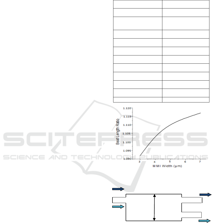
Table 1: Parameter for demultilpexer MMI structure.
Parameter Value
Guide Refractive index 3.290
Cladding Refractive
index
3.167
I/O waveguide width 0.8 μm
λ
1
1490 nm
λ
2
1310 nm
MMI width 3.4 μm
MMI length 449 μm
Polarization TE
BPM Solver Paraxial
Engine Finite Difference
Boundary Condition TBC
Figure 1: Calculated beat length ratio (L
π
1310
/L
π
1490
) as a
function of MMI width for TE polarization.
1490nm 1490 nm
Port 1 Port 2
1310 nm 3.4 µm
Port 3
1310 nm
Figure 2: Schematic diagram of the proposed
demultiplexer.
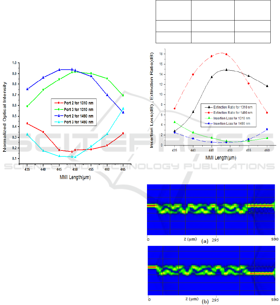
3 RESULTS AND DISCUSSTION
From Fig. 3, it can be observed that wavelength 1310
nm is obtained at port 3 with highest optical intensity
while wavelength 1490 nm is obtained at port 2 with
highest optical intensity at MMI length of 449µm for
PHOTOPTICS 2016 - 4th International Conference on Photonics, Optics and Laser Technology
226
separation distance between output waveguides to be
1.4 µm and input lateral offset as 1.1 µm. Further, to
measure the performance of device, Extinction Ratio
and Insertion Loss has been calculated using the
relations:
Extinction Ratio = 10 log (P
d
/ P
u
)
(3)
Insertion Loss = -10 log (P
d
/P
i
) (4)
where P
d
is the power from desirable output
waveguide, P
i
is the power in input waveguide and P
u
is the power from undesirable output waveguide (Shi
et al., 2007). From fig. 4, it is clear that optimized
length is 449 µm.
Figure 3: Normalized field distribution versus MMI Length
for λ=1310 nm and 1490 nm wavelength for TE
polarization.
Two dimensional simulations of field distribution
for TE polarization can be seen in Fig. 5, where 1490
nm get separated at port 2 and 1310 nm at port 3. We
have also optimized the output by varying the gap size
between output waveguides and simultaneously
changing the corresponding lateral offset of input
waveguide. From fig. 6, we can observe that the
output has been optimized at a gap size of 1.3 µm or
a lateral shift of 1.05 µm.
Table. 2 and Fig. 6 show that the insertion loss for
both the wavelengths is below 1dB and and extinction
ratio for 1310 nm and 1490 nm are around 17 dB and
20dB at optimized MMI length of 449 µm. TM beat
lengths were also calculated but the optimized MMI
length was different as compared to its TE
counterpart. For TM mode, optimized MMI length
was found to be 440µm. This shows that optimum
value for both polarizatios are different and hence we
have optimized our designed demultiplexer only for
TE polarization.
Table 2: Output Powers (normalized to input power) of two
output ports of the proposed demultiplexer at two
wavelengths.
Wavelength
(nm)
Extinction
Ratio
(dB)
Insertion
Loss
(dB)
1310 16.93 0.924
1490 20.17 0.546
Figure 4: Simulation performance for TE mode as a
function of MMI length.
Figure 5: 2-D simulations of the field distribution (a) port 2
for wavelength 1490 nm and (b) port 3 for wavelength 1310
nm.
Performance Analysis of 1310/1490 Nm Demultiplexer based on Multimode Interference Coupler for PON
227
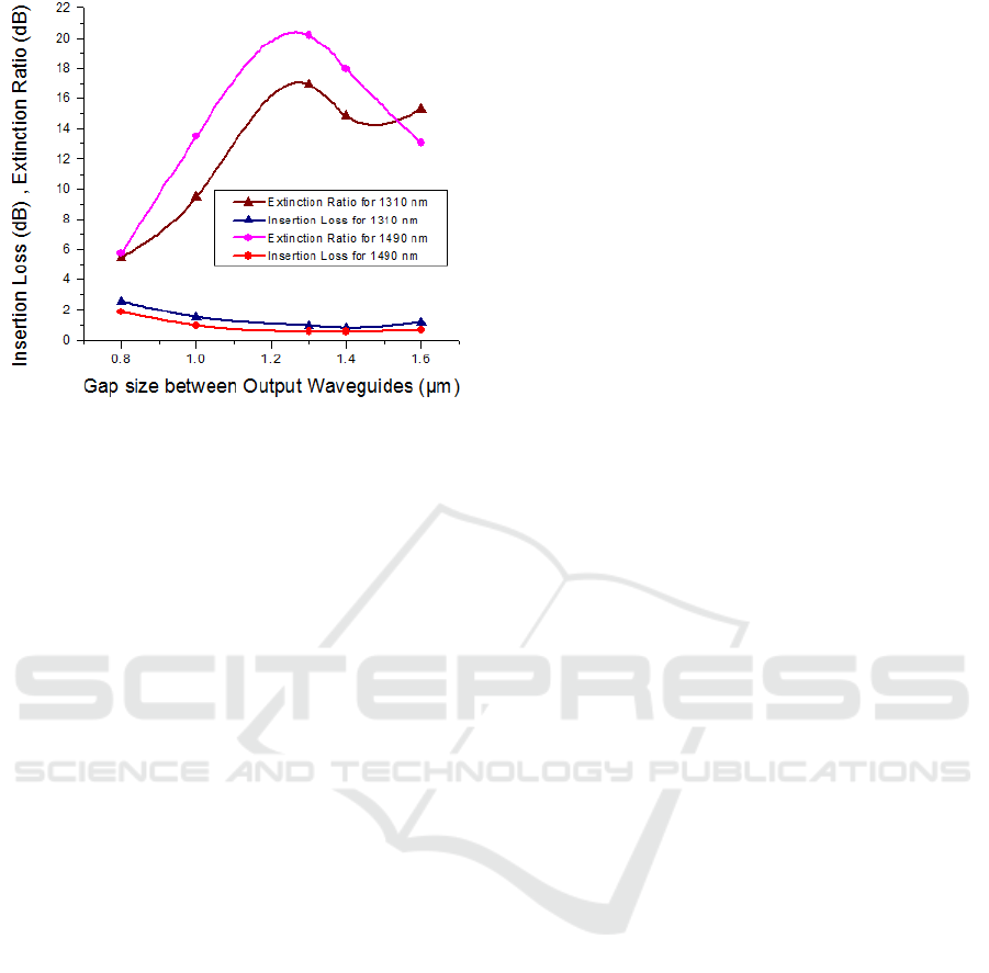
Figure 6: Simulation performance for TE mode as a
function of branching separation distance (Gap size)
between output waveguides.
4 CONCLUSIONS
A 1310/1490 nm wavelength demultiplexer has been
proposed based on conventional MMI structure. It has
been shown that separation distance between output
waveguides and the lateral offset of input waveguide
affect the simulation output and we optimized the
branching separation distance at 1.3 μm to achieve
maximum output optical field for demultiplexer. The
present simulation based on finite difference beam
propagation shows that the proposed demultiplexer
has good performances such as a low insertion loss
and a high extinction ratio at 1310 nm wavelength,
which has been found to be IL= 0.924 dB and
extinction ratio = 16.93 dB, respectively, and at 1490
nm wavelength, IL= 0.546 dB and extinction ratio =
20.17 dB, respectively, for quasi-transverse-electric
(quasi-TE) polarization. The 1310/1490 nm
wavelength demultiplexer may be an important key
component in application of Passive Optical Network
communication system in near future.
REFERENCES
Fan, S.H., Guidotti, D., Chien, H.C. and Chang, G.K., 2009,
May. A novel compact polymeric wavelength
triplexer designed for 10Gb/s TDM-PON based on
cascaded-step-size multimode interference. In
Electronic Components and Technology Conference,
2009. ECTC 2009. 59th (pp. 220-223). IEEE.
Cale, I., Salihovic, A. and Ivekovic, M., 2007, June. Gigabit
passive optical network-GPON. In Information
Technology Interfaces, 2007. ITI 2007. 29th
International Conference on (pp. 679-684). IEEE.
FILKA, M., 2009. Optoelectronics: for telecommunications
and informatics. Brno, ISBN 978-0- 615-33185-0,
pp.978-80.
The Fiber Optic Association, Inc, 2010-2014 “Fiber Optic
Network Optical Wavelength Transmission Bands”,
Guide to Fiber Optics and Premises cabling,
http://www.thefoa.org/tech/ref/basic/SMbands.html.
Horváth, T., Kočí, L., Jurčík, M. and Filka, M., 2015.
Coexistence GPON, NG-PON, and CATV systems. ,
International Journal of Engineering Trends and
Technology Volume 21, pp. 61-66.
Soldano, L.B. and Pennings, E., 1995. Optical multi-mode
interference devices based on self-imaging: principles
and applications. Lightwave Technology, Journal of,
13(4), pp.615-627.
Chack, D., Kumar, V. and Raghuwanshi, S.K., 2015.
Design and performance analysis of InP/InGaAsP-
MMI based 1310/1550-nm wavelength division
demultiplexer with tapered waveguide geometry. Opto-
Electronics Review, 23(4), pp.271-277.
Chack, D., Agrawal, N. and Raghuwanshi, S.K., 2014. To
analyse the performance of tapered and MMI assisted
splitter on the basis of geographical parameters. Optik-
International Journal for Light and Electron Optics,
125(11), pp.2568-2571.
Jerabek, V., Busek, K., Prajzler, V., Mares, D. and
Svoboda, R., 2013. The design of polymer planar
optical triplexer with MMI filter and directional
coupler. Radioengineering, 22(4).
Shi, Y., Anand, S. and He, S., 2007. A polarization-
insensitive 1310/1550-nm demultiplexer based on
sandwiched multimode interference waveguides.
Photonics Technology Letters, IEEE, 19(22), pp.1789-
1791.
Paiam, M.R., Janz, C.F., MacDonald, R.I. and Broughton,
J.N., 1995. Compact planar 980/1550-nm wavelength
multi/demultiplexer based on multimode interference.
Photonics Technology Letters, IEEE, 7(10), pp.1180-
1182.
Li, M., Zhang, C., Zhu, H. and Chen, M., 2011, November.
Design and fabrication of a 1-by-4 multimode
interference splitter based on InP. In SPIE/OSA/IEEE
Asia Communications and Photonics (pp. 83072M-
83072M). International Society for Optics and
Photonics.
Adachi and Sadao,”Refractive indices of III–V compounds,
1982: Key properties of InGaAsP relevant to device
design”, J. Appl. Phys. 53, 5863–5869.
Chang, H.H., Kuo, Y.H., Jones, R., Barkai, A. and Bowers,
J.E., 2010. Integrated hybrid silicon triplexer. Optics
express, 18(23), pp.23891-23899.
PHOTOPTICS 2016 - 4th International Conference on Photonics, Optics and Laser Technology
228
