
MOF-VM: Instantiation Revisited
Terje Gjøsæter, Andreas Prinz and Jan P. Nytun
Faculty of Engineering & Science, University of Agder, Grimstad, Norway
Keywords:
Model Driven Architecture, Meta-Modelling, Instantiation.
Abstract:
The Model-Driven Architecture (MDA) is based on an understanding of a hierarchy of levels that are placed
on top of each other and that are connected with instantiation. For practical MDA use, it is important to be
clear about the kinds of objects that reside on the different levels and the relations between them as well as
relations to objects outside of the MDA domain. This article aims at enhancing the understanding of these
objects and relations by relating them to a virtual MOF machine.
1 INTRODUCTION
Modelling and metamodelling are trendy, and there
are several tools supporting it. Everyone knows the
important concepts in this area. However, during dis-
cussions with practitioners of MDA it becomes clear
that in some circumstances, the details of the under-
standing can differ, even among experts. This is most
often caused by differences in the way the concepts
are related to each other and to real scenarios. This
article aims at clarifying the concepts and their con-
nections, with particular focus on instantiation.
OMG has put forward the idea of a model-driven
architecture (MDA). Both MOF and UML are con-
sidered the key languages of the MDA, but the gen-
eral MDA setup includes also other languages. MDA
is based on an understanding of a four-level hierar-
chy of abstractions. The lowest level, called M0, is
traditionally reserved for concrete objects. The next
level (M1) is devoted to the models that describe those
objects. On top of M1 there is a level describing
how models are formed, which is a meta-model level,
called M2. Finally, the architecture is closed with a
level M3 (meta-meta-model) that is supposed to de-
scribe M2 as well as describing itself.
The basic and important relation between levels
is instantiation, i.e., the lower level is an instance of
the upper level. The relation between M1 and M2 is
the same as the relation between M2 and M3. In the
same style, also the self-referencing relation between
M3 and M3 (where the second M3 is used in the place
of M4) is of the same nature. It appears that the rela-
tion between levels is essentially the well known type-
element pattern (also known as set-element pattern),
see also (Favre, 2004). This is the relation between
definition and use, which is also the classical “meta”-
relation as for example stated in (Bézivin and Gerbé,
2001). The v2.4.2 MOF specification also emphasises
this in (Editor, 2014):
“Note that key modeling concepts are Clas-
sifier and Instance or Class and Object, and
the ability to navigate from an instance to its
metaobject (its classifier). This fundamental
concept can be used to handle any number of
layers (sometimes referred to as metalevels).
The MOF 2 Reflection interfaces allow traver-
sal across any number of metalayers recur-
sively.”
From a tool developer’s perspective it may even be
beneficial to treat all levels and level transitions the
same way and disregard their absolute numbering, as
proposed in (Mu et al., 2010).
1.1 Motivation
Although this architecture looks quite simple and
clear to start with, there is ongoing discussion to
change the architecture and its basic understanding, as
evidenced by (Atkinson, 1997; Atkinson and Kühne,
2000; Atkinson and Kühne, 2002; Atkinson and
Kühne, 2003; Atkinson and Kühne, 2005; Bézivin
and Gerbé, 2001; Eriksson et al., 2013; Favre, 2004;
Gitzel et al., 2007; Hesse, 2006; Kühne, 2006). From
this, the basics of meta-modelling and instantiation
appear far from clear. Beginners, casual users and ex-
perts of MDA and UML lack a common understand-
ing of the nature of the levels as well as their rela-
tion to each other in terms of instantiation. In particu-
lar, this is a problem when real objects are concerned.
Gjøsæter, T., Prinz, A. and Nytun, J.
MOF-VM: Instantiation Revisited.
DOI: 10.5220/0005606101370144
In Proceedings of the 4th International Conference on Model-Driven Engineering and Software Development (MODELSWARD 2016), pages 137-144
ISBN: 978-989-758-168-7
Copyright
c
2016 by SCITEPRESS – Science and Technology Publications, Lda. All rights reserved
137
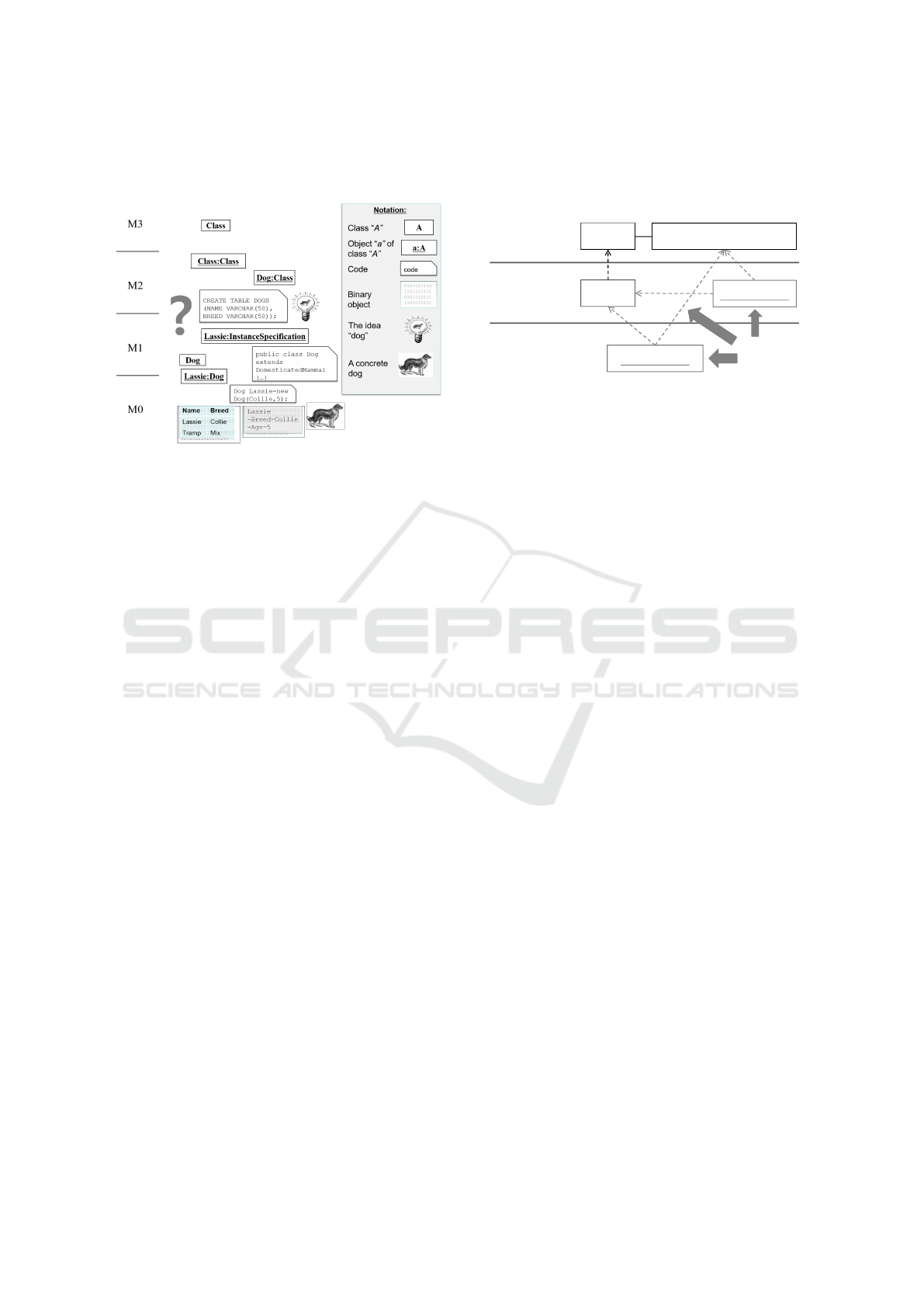
This leads to discussion about which level entities be-
long to, for example those of Fig. 1.
Figure 1: Where do the different entities belong?
Similar questions are easily answered for pro-
gramming languages, but are difficult in a UML set-
ting when UML is used for sketching and documen-
tation in addition to code generation. Using UML
in such a descriptive style relates to the first matu-
rity level (Kleppe and Warmer, 2003) of model-driven
technology. However, the current trend is to approach
higher maturity levels, such that models will be used
more and more prescriptively (modelling as program-
ming). This is also the basis for our approach.
1.2 Problem Statement
We use the following questions to clarify the issues
with instantiation and some of their implications.
1. How do UML instances relate to MDA instances?
2. How does reality relate to the modelling?
3. How do binary objects relate to the modelling?
4. What is the nature of M0?
5. How to formalise the semantics of the MDA?
6. How to define the semantics of instantiation?
The first four questions are important for users of
UML and other MDA-based languages, while the last
two are more relevant for language developers. In the
following, we explain these questions in more detail.
How do UML instances relate to MDA instances?
UML allows to specify instances by using the
InstanceSpecification meta-class of its meta-
model, see also Fig. 2 for an example. Similarly, it
is possible to specify a class using UML’s meta-class
Class. Additionally, one may specify an instanceOf
relation between an instance and a class. Since we as-
sume that a UML specification resides at one level
only, then this last mentioned instantiation contra-
dicts the idea of instantiation being a cross-level con-
cern. Fig. 2 visualises the dilemma where instance
10.08.2012
1
Class
Figure 2: problem.pdf
M2
UML
InstanceSpecification
Person
M1
UML Model
Ann:Person
M0
Model Instance
New Version
?
Ann:Person
Figure 2: Problem with the OMG level architecture.
Ann:Person is an instance of class Person and con-
sequently placed on M0, but since Ann:Person is also
an instance of InstanceSpecification it should be
placed on M1.
It appears that we look at two kinds of instantia-
tion, one defined in UML as a relation instanceOf and
one given by MDA as the level crossing instantiation
relation. Some authors (Eriksson et al., 2013; Hesse,
2006; Kühne, 2006) call the UML relation for onto-
logical instantiation while the MDA relation is called
linguistic instantiation.
How does reality relate to the modelling?
Models are normally related to a reality, and it is
not too obvious how this connection is done with the
MDA. One approach is to consider the level M0 to
hold the real objects, which makes this level incon-
sistent with the other levels. If, however, reality is
placed outside of the stack, the question remains how
the relation to reality is achieved.
How do binary objects relate to the modelling?
All entities that are handled by the MDA, and all
model elements given by the various models in the ar-
chitecture are abstract entities. In the computer they
normally appear as objects in some programming lan-
guage, or as some bits. But how do the model ele-
ments match with the realities in the computer?
What is the nature of M0?
M0 is special, since it is the lowest level and does
not enable further instantiation. How is M0 compat-
ible with the other levels? Does it contain model in-
stances, run time objects or real-world objects? Does
it have any practical purpose at all except as a theo-
retical concept?
How to formalise the semantics of the MDA?
With a powerful platform like MDA and powerful
languages like UML and MOF it is natural to think
of capturing the semantics of the platform itself us-
ing the MDA and its languages. However, such an
endevaour is tricky, since it is not clear what is being
defined and what is being used.
MODELSWARD 2016 - 4th International Conference on Model-Driven Engineering and Software Development
138
How to define the semantics of instantiation?
The MDA is about languages. MOF allows to de-
fine the abstract syntax of languages; and with these
syntaxes, specifications and models can be created.
However, it is also important to make clear which
concepts of the language can be instantiated and how.
How can we specify that classes can be instantiated,
but packages cannot? How can a language designer
specify what the intended instantiation should be?
This problem is sometimes attempted solved with
multi-level instantiation (Atkinson and Kühne, 2001).
1.3 Structure of this Article
We continue this article with Section 2 containing
definitions of the relevant main concepts of meta-
modelling. In Section 3, we look at the issues given
in Section 1 and provide a solution to them. Finally,
we summarise in Section 4.
2 LEVELS AND INSTANTIATION
To better understand the questions, we will look at the
basic definition-use pattern behind instantiation. Af-
terwards, we look at the general understanding behind
the idea of modelling levels and finally we consider
relations between levels and realities inside and out-
side the computer. Note that we are concerned with
semantics of instantiation, semantics of runs is out-
side the scope of this article.
2.1 Definition and Use
Computer objects can be classified according to the
notion of modelling time (the time of definition) and
run time (the time of use). The modelling (descrip-
tion) time is when the model is created. At this time,
the model is changeable by tools.
A computer model definition is the description of
all possible structures that may exist during run time
of the model. After modelling time, the model is con-
sidered fixed, and it may then be used at run time.
The things defined in the model come to life. Use of
the model is the selection of one of the possible struc-
tures from the model, e.g. by taking a snapshot of the
running model.
Most often, there are tools between these two
phases, the most obvious one being a compiler. An
interpretive approach could open up for changes in
the definition at run time. Still, also in this case the
description has to be created before it can be used.
This definition-use pattern, also known as type-
element pattern, is a very basic pattern for program-
ming, forming the foundation for patterns such as
object-oriented programming (see Fig. 3).
Figure 3: The type-element pattern and object-orientation.
The type-element pattern emerged already in the
very first days of computers establishing a distinction
between a definition (the code) and the use of it on ob-
jects (data). In modern computers this is fixed to the
extent that it is even manifest in operating systems:
There are codepages (read only), and data pages.
We want to highlight the following three points.
• Execution (use) of the model is a goal, and mod-
elling (definition) is a stage to make execution
possible. However, execution cannot be achieved
directly; a description to be executed is needed.
• The distinction between modelling time and run
time is not that sharp, since the definition has to
exist at use time in some form.
• The connection between definition and use is
given by a semantic function, associating the def-
inition with a set of possible uses. The semantics
of a definition (type) is a set, and a use (element)
is an element of this set (Fig. 3).
The same distinction is used in the OMG stack,
with one more extension. Here, definition as well
as use refer to roles, not to absolute properties. This
means that the same entity can be both use and defi-
nition depending on context,
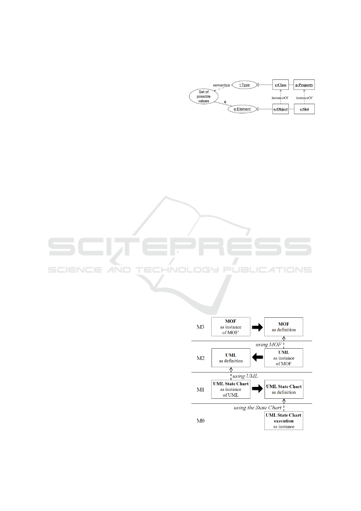
Figure 4: Definition and use related to modelling levels.
MOF-VM: Instantiation Revisited
139

as depicted in Fig. 4 by the solid arrows. The
relation between definition and use is the essence of
the relation between adjacent levels. The definition of
a program on M1 is related to a use (a run) on level
M0. The definition of a language on M2 is used for
(the definition of) a program on M1. Finally, the def-
inition of a meta-language on M3 is used on the level
M2. Please note that the elements on M2 and M1 are
used to define elements on the next lower level. This
is possible since they function as a definition in one
context and as a use in another context. When we
look at the different roles in the OMG stack (Fig. 4),
then it becomes obvious that the relation between two
adjacent levels is based on the definition-use pattern.
Often, it is also required that a level boundary is the
only place for the definition-use pattern, leading to a
property known as strict meta-modelling. Strict meta-
modelling defines linear meta-model hierarchies, see
(Atkinson and Kühne, 2002; Gitzel et al., 2007).
When dealing with meta-levels to define lan-
guages there is a double definition-use pattern of three
levels that has to be taken into account: the lan-
guage specification (meta-model), the user specifica-
tion (model), and objects of the model (instances).
This structure forms a pattern that can be applied
recursively to raise an arbitrary number of levels.
MOF is also subject to this 3-level-schema and in the
four-level meta-model hierarchy, MOF is commonly
referred to as a meta-meta-model, even though strictly
speaking it is a meta-model. So the underlying pat-
tern of the MDA is a repetition of this 3-level-schema:
M0-M1-M2, M1-M2-M3, M2-M3-M3.
2.2 MDA and the MOF-VM
A running MOF implementation has to represent
classes and objects at run time and preserve connec-
tions between them, allow creation of objects based
on class/type and provide information about model
elements on request. For a general discussion of im-
plementations of MOF and the MDA architecture in a
platform, we would like to introduce the concept of an
abstract MOF Virtual Machine (MOF-VM) as the core
of such a system. Just like a Java specification comes
to life in a Java Virtual Machine, a MOF specifica-
tion comes to life in the MOF-VM. Java classes are
mostly mapped 1:1 to corresponding JVM classes, but
they are not identical. The same is the case for MOF
classes versus classes in the MOF-VM. For defining
a MOF class, we use the MOF language in an appro-
priate editor, but to execute it (e.g. instantiate it), we
need to use the corresponding class in the MOF-VM.
The essence of the level-crossing relation in MDA
is the instantiation, as given by the class-object rela-
tion and implemented in the MOF-VM. Fig. 3 shows
how this is a special case of the type-element pattern.
In (Rumbaugh et al., 2005) James Rumbaugh et al.
describe instantiation as the creation of new instances
of model elements, where the instances are the result
of primitive create action(s) or creation operation(s).
“Usually, each concrete class has one or more
class-scope (static) constructor operations, the
purpose of which is to create new objects of
the class. Underlying all the constructor oper-
ations is an implicit primitive operation that
creates a new raw instance that is then ini-
tialised by the constructor operation...”
This implicit primitive operation mentioned is
the core of MOF-VM, denoting the relation between
Class and Object considered as type and element, not
the UML or MOF classes and objects.
Instantiation spans a relation between something
instantiable and an instance. When the instance is es-
tablished, the specification may be seen as a descrip-
tion of it, i.e., the instance fits the description. The
term description is here used in a type-like fashion.
The instance may fit many descriptions and the term
instanceOf can be used even if the description was
not used when the instance was created.
Since in MDA all objects are defined using
classes, which again are objects themselves, the most
natural thing to do is to define a hierarchy of these
objects related to the MOF-VM instantiation.
2.3 MOF-VM Notation
After having defined the object-oriented point of view
as reflected in the MOF-VM, we have also defined the
boundaries of our world. The computer contains ob-
jects defined by classes, and that’s all. Because of this
very simplifying view, we can now consider every-
thing in the computer as an object. That means that
we may do two things: firstly, we may represent (in-
ternally) all objects uniformly, and secondly we may
present (externally) all objects uniformly. Both are
possible with the introduction of the MOF-VM.
The object-oriented point of view of MOF-VM
does not have a concrete notation. It is just an ab-
stract meta-structure giving an understanding of the
world. The case of representing elements of an
object-oriented system or platform such as the MOF-
VM, has been handled in (Nytun, 2010).
A MOF-VM notation allows the MOF-VM to uni-
formly present classes and objects of arbitrary lan-
guages. The language UML provides a convenient
notation for both objects and classes as well as for
the relation between them. Because of this, it is of-
ten used as a MOF-VM notation. Like Java may be
MODELSWARD 2016 - 4th International Conference on Model-Driven Engineering and Software Development
140
used as a notation to present objects in the Java Vir-
tual Machine during run time, we may choose to use
UML to present elements of the MOF-VM during run
time too. It is essential to note that UML is outside
the four-level MDA architecture when it is used as a
MOF-VM notation.
2.4 Meaning and Realisation
We will now look at the meaning of the models. In
(Kühne, 2006) it is claimed that the meaning of class
Collie is the concept of collie, and the meaning of
Lassie is a particular dog. Of course, this is a com-
mon idea and not unusual in a UML context. How-
ever, defining the meaning like that is not as easy as
it looks. As there are different ideas of the concept
collie, the meaning would not be fixed in the sense
that we all agree on the meaning. The same is true
for Lassie, several dogs have played the role of being
Lassie – which of those is then the meaning of Lassie?
Both the concrete dog and the collie concept are just
possible meanings. Therefore, we prefer to use the
word interpretation, rather than meaning.
So we distinguish between an individual meaning
of a model element, which we call interpretation, and
a common meaning of a model element, called se-
mantics. The semantics is the intersection of all con-
sistent interpretations, such that each consistent inter-
pretation is a special case of the semantics. Another
way of formulating this is considering the semantics
to be the set of all consistent interpretations on an ap-
propriate level of abstraction.
While the semantics dimension is primarily con-
cerned with reality outside computers, the realisa-
tion dimension, as introduced by Jean-Marie Favre in
(Favre, 2003) is concerned with reality inside com-
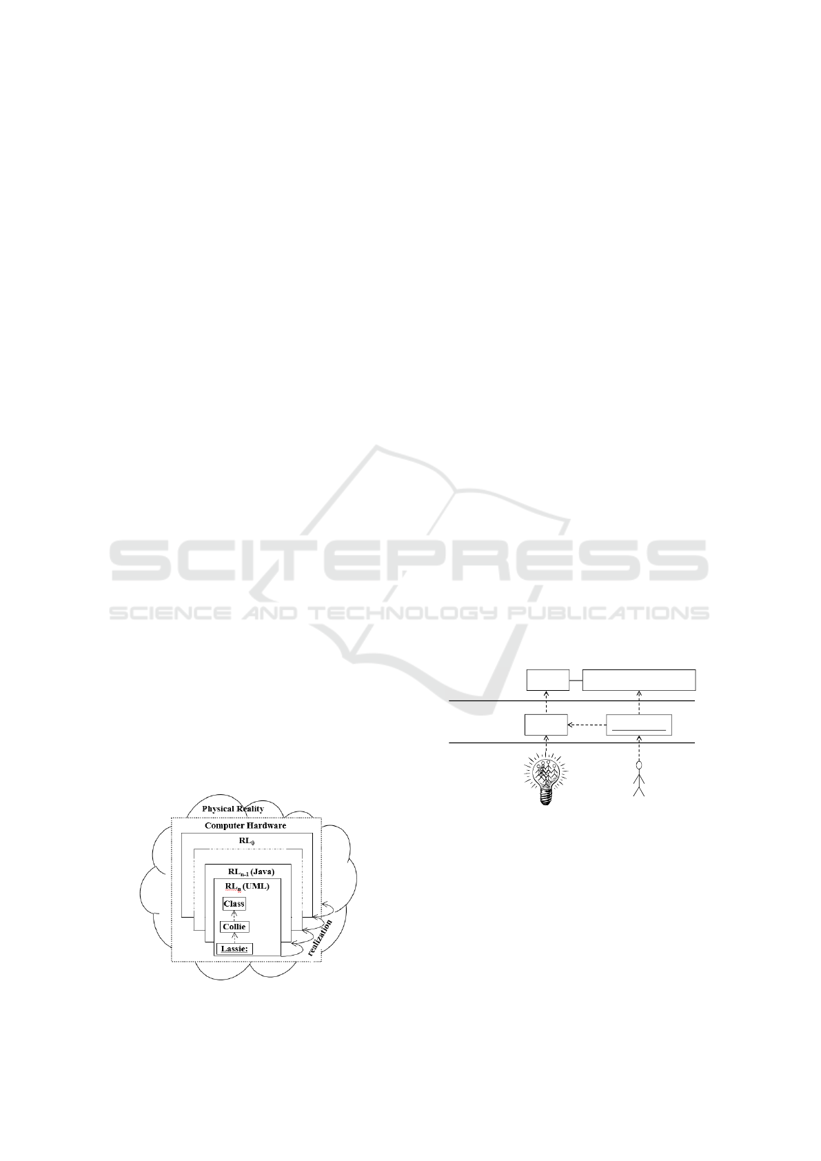
puters. In Fig. 5, we use a cloud to show the physical
reality. Abstractions are embedded as squares into it,
indicating realisation levels. There are several layers
of realisations, which represent different levels of ab-
Figure 5: Realisation levels.
straction of reality. For example, it is possible to un-
derstand a UML instance on the level of UML or on
the level of the implementation language Java or on
the level of Java byte-code, or as bits and so on. To
come from one realisation layer to the next it is usu-
ally necessary to perform a compilation or execution.
These processes continue until the physical reality is
met. While a final compilation to machine code gives
direct execution by the physical processor (or proces-
sors), software interpreters may execute code given
on a higher level of abstraction.
3 SOLUTIONS
We will use the definitions of Section 2 to answer
each of the questions of Section 1, and in particular
the paradox related to InstanceSpecification and
M0. For each question, we will provide a short and
concise answer, and then discuss alternative views.
How do UML instances relate to MDA instances?
Concerning InstanceSpecification, they are
objects like any other, but showing an instanceOf re-
lation to a UML class. Concerning MOF-VM in-
stances, they are in a type-element relationship with
their corresponding MOF-VM class, shown with the
same notation.
The problem of Fig. 2 is a known problem, and
there have been several proposals to solve it. A com-
mon solution seems to be the one described in (Atkin-
son and Kühne, 2003), which is illustrated in Fig.
6. This solution basically moves the model elements
10.08.2012
1
Figure 3: solution.pdf
Class
InstanceSpecification
Person
Ann:Person
M2
UML
M1
UML Model
M0
Model Instance
Figure 6: The UML 2.0 and MOF2.0 standards solution of
the problem according to (Atkinson and Kühne, 2003).
from M0 into M1 and sees M0 as composed of real
world objects and by this M0 has been removed from
the meta-model stack. In this view M1 is seen as com-
posed of two levels: One for user classes and one for
models of objects of these classes. This allows the in-
stanceOf -relation between user classes and their ob-
jects to be explicitly modelled at the M2 level and
then explicitly shown at the M1 level. This view is
also advocated in (Wikipedia, 2015).
MOF-VM: Instantiation Revisited
141
This solution solves the problem with the
InstanceSpecification, but it breaks the symme-
try and beauty of the original MDA approach, e.g., it
obscures seeing one level as description of sets with
corresponding elements of these sets at the next lower
level in the overall architecture. Moreover, it leads
to serious problems when one wants to use modelling
for languages (one level up).
An object on M0 could be presented by using
the same syntax as used when showing instances of
InstanceSpecification at M1 – this may confuse
some users since there could be two entities on two
different levels looking exactly the same. However,
such two entities are not the same, they are funda-
mentally different and only look the same because the
UML-based MOF-VM notation used for displaying
elements on M0 is similar to UML.
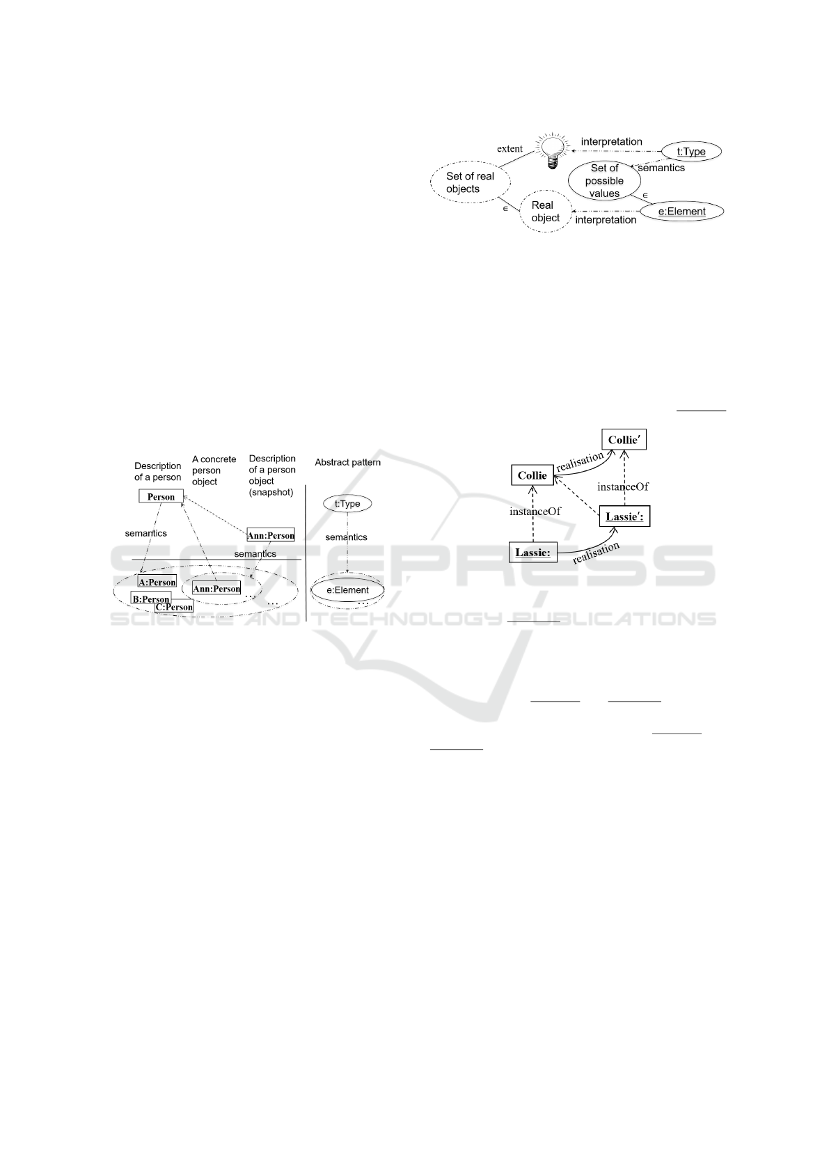
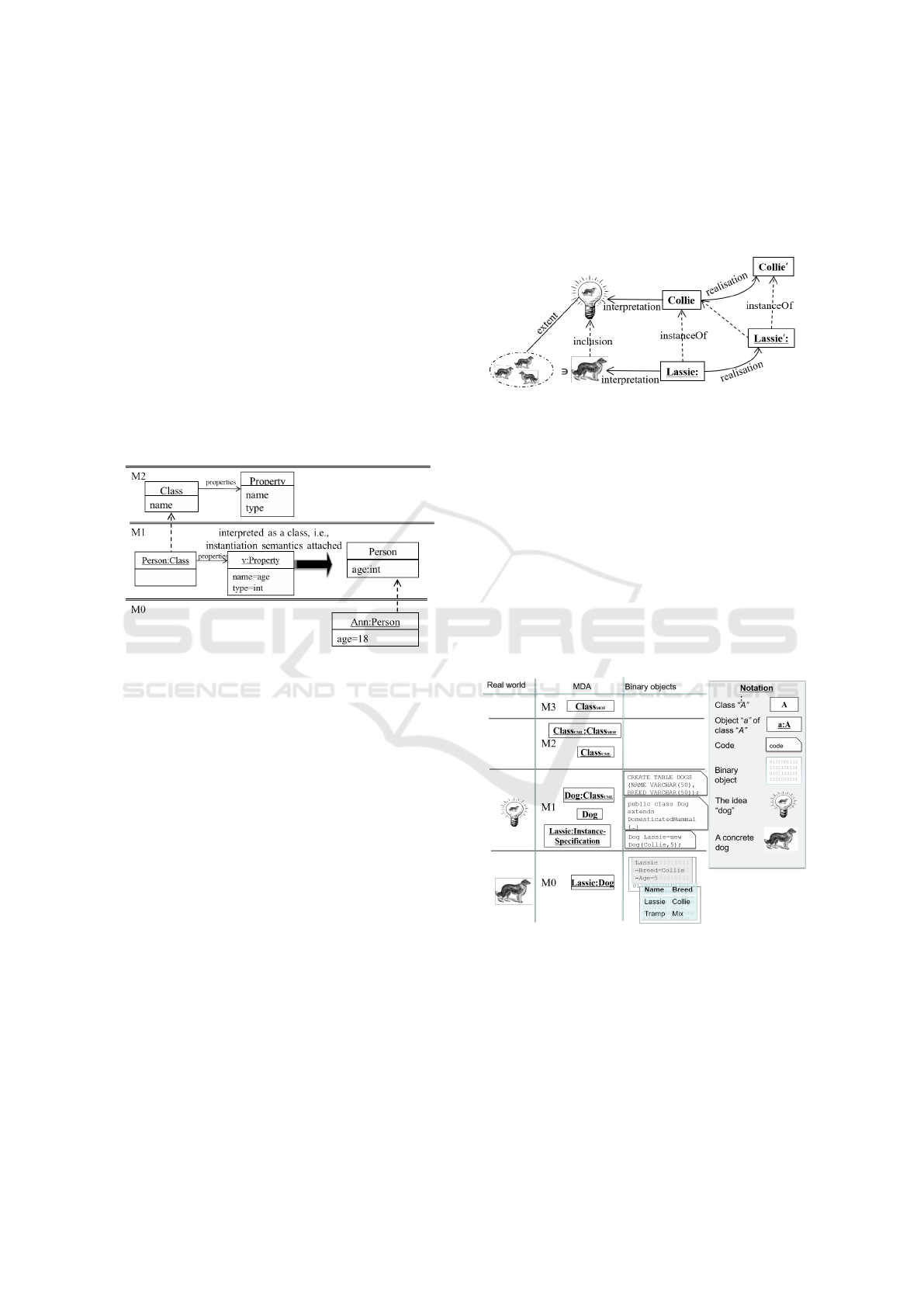
Fig. 7 illustrates our understanding of instantiation
as related to the MOF-VM. The semantics of class
Figure 7: Semantics - from element to set.
Person on M1 (in UML) is a set of Person objects.
On M0, the Ann:Person object (in MOF-VM nota-
tion) is an element in this set, and can be interpreted
as referring to one concrete person. The abstraction of
the concrete person would be the object on M0. On
the right, we see how this instantiation corresponds to
the abstract pattern of Type and Element. In MOF-
VM, types are classes with properties and elements
are objects with slots.
It is important to distinguish between two types of
instantiation: level-crossing (linguistic) instantiation
in the sense of the MOF-VM, and language-defined
(ontological) instantiation as for example given in
UML using InstanceSpecification. Ontological
instances relate to their definition by means of an in-
terpretation, or semantics.
How does reality relate to the modelling?
Model and reality are related through interpreta-
tion, see Fig. 8.
Models cannot relate to reality through language
semantics, since language semantics is given on the
level of language and not for the specification. It is
Figure 8: Interpretation and semantics.
also not possible that reality is in M0 via instanceOf,
see the discussion of the nature of M0.
How do binary objects relate to the modelling?
Realisation means to create a concrete instance of
the abstract MOF-VM. This belongs to the implemen-
tation dimension, and is not part of the MDA stack.
Fig. 9 shows the relation between realisation and
instantiation. Lassie, a real-world object of type Col-
lie is being modelled. The abstract instance Lassie:
Figure 9: Realisation and instantiation.
is realised as Lassie
0
: through compilation into ex-
ecutable form, and Collie is realised as Collie
0
.
Collie
0
may or may not be explicitly defined. In
this sense, not realisation objects, but their abstrac-
tions are inside the MDA stack.
Conceptually, Lassie: and Lassie
0
: are located
on the same meta-level (Collie and Collie
0
are on
the same meta-level above). However, Lassie: and
Lassie
0
: are on different realisation levels.
What is the nature of M0?
M0 contains linguistic instances of M1 classes.
As discussed in Section 2, the relation between
M1 and M0 is the definition-use relation. However,
M0 is special since it may only contain terminal el-
ements – no further instantiation is possible and this
makes M0 the lowest level. This agrees with the ideas
in (Bézivin and Gerbé, 2001; Favre, 2003; OMG Ed-
itor, 2011; Tony Clark and Williams, 2004).
The real-world objects do not reside on level M0
as advocated by e.g. (Eriksson et al., 2013; Skene,
2007). Instead, an interpretation relates the instances
to the real objects.
How to formalise the semantics of the MDA?
The semantics of the MDA can be formalised by
specification of the MOF-VM as semantics of MOF.
MODELSWARD 2016 - 4th International Conference on Model-Driven Engineering and Software Development
142
The MOF specification (Editor, 2014) specifies a
“MOF-VM”. MOF and the MOF-VM are defined us-
ing features that belong to UML. This facilitates a
possible misunderstanding that these features belong
to MOF and are re-used from MOF in UML.
The MDA stack cannot be defined using MOF,
because the semantics of the multi-level MDA archi-
tecture has to be defined by something existing out-
side the architecture itself. MOF as a language exists
within the levels of this architecture and is bound by
it. However, a UML-like notation may be used to de-
note elements of the architecture. Similarly, the MOF
semantics can be used to define the MDA semantics.
How to define the semantics of instantiation?
The semantics of instantiation is defined by map-
ping language instances to MOF-VM classes in order
to use the built-in instantiation from MOF-VM.
Figure 10: Giving instantiation semantics.
The semantics (or meaning) of instantiation is es-
sentially the relation between definition and use. In
Fig. 10 this is shown in more detail than in Fig. 4.
Instantiating class Class gives an object; more gen-
erally, in this architecture instantiating a model gives
an object structure composed of objects with slots and
links between the objects. This instantiation is possi-
ble because class Class is instantiable. The instantia-
tion itself is given by MOF-VM.
To make instances of class Class also instantiable,
for example for the object Person:Class, a rela-
tion to MOF-VM instantiation has to be established.
In particular, Person:Class has to be marked as a
MOF-VM Class having its attributes as MOF-VM
Properties. This turns the object structure Person into
a MOF-VM type. After this relation is established,
Person has instantiation semantics, i.e., it can be in-
stantiated at the next lower level.
4 SUMMARY
In this article, we have taken some questions and is-
sues with a lack of a common understanding among
students and practitioners of the MDA. We have at-
tempted to clarify them and recommend beneficial
approaches, based on careful examination of related
languages, relevant concepts, and related research in
meta-modelling. Fig. 11 shows the relation beween
Figure 11: Interpretation, realisation and instantiation.
the levels of the modelling domain, the real world and
the reality inside the computer as connected through
instantiation, interpretation and realisation, respec-
tively. M0 is a valid part of the MDA architecture,
containing instances of M1 elements, so Lassie: is
an M0 instance of Collie. The semantics of Collie
define the set of all possible instances of the class.
Fig. 12 revisits the elements of Fig. 1 and places
them in the proper place according to the discus-
sions above. A UML-based MOF-VM notation is
used for presenting elements of the MDA here. For
clarity, Class elements have been marked as either
MOFClass or UMLClass.
Figure 12: Correct placement of the different entities.
A (meta-)model is defined on one level, and used
on the level below to define a new model. This sep-
aration of definition and use forms the fundamental
reason for the introduction of levels. The relation be-
tween M1 and M0 is not special. However, M0 is
special since it may only contain terminal elements –
no further instantiation is possible.
Formally, instantiation means taking an element
from the set formed by the semantics of a class on
MOF-VM: Instantiation Revisited
143

one level, and using it on the level below. The new
element may itself have semantics of a set of el-
ements, and can then be instantiated further. The
InstanceSpecification of UML does not spoil
this approach, it just defines a subset of the instances
of the classifier specifying fixed slot values together
with other constraints.
For simplicity of discussing platforms that support
the MDA, we have introduced the concept of an ab-
stracted MDA platform implementation that we call
the MOF-VM – a MOF virtual machine. MOF-VM
does not come with a native presentation language. It
is common to use UML notation. However, it is im-
portant to notice that UML is used as a notation for the
MOF-VM platform, not as an independent language.
The semantics of the MDA is formalised by a
specification of the semantics of the MDA platform.
In the same way as the Java semantics may be for-
malised through a specification of the Java VM, we
can think of the MOF-VM as an interpreter of MOF-
based models. Like Java is transformed into byte-
code for instantiation and execution in the Java-VM,
the instantiation semantics of MOF can be handled
with a mapping of model elements to MOF-VM
classes to use the built-in instantiation of MOF-VM.
We have pursued the language design perspective
here. If UML was used primarily as a notation, the se-
mantics could be disregarded and its role in the MDA
architecture might take different forms than what we
have described. This may lead to a different view
on the MDA which is based on a different perspec-
tive where semantics are less important. For language
modelling, however, a uniform instantiation seman-
tics between levels is essential.
REFERENCES
Atkinson, C. (1997). Meta-modeling for distributed ob-
ject environments. In In Enterprise Distributed Object
Computing, pages 90–101. Published by IEEE Com-
puter Society.
Atkinson, C. and Kühne, T. (2000). Meta-level indepen-
dent modelling. In International Workshop on Model
Engineering at 14th European Conference on Object-
Oriented Programming.
Atkinson, C. and Kühne, T. (2001). The essence of multi-
level metamodeling. In UML 2001-The Unified Mod-
eling Language. Modeling Languages, Concepts, and
Tools, pages 19–33. Springer Berlin Heidelberg.
Atkinson, C. and Kühne, T. (2002). Rearchitecting the
UML infrastructure. ACM Transactions on Computer
Systems (TOCS),, 12(4):290–321.
Atkinson, C. and Kühne, T. (2003). Model-driven develop-
ment: A metamodeling foundation. Software, IEEE.
Atkinson, C. and Kühne, T. (2005). Concepts for comparing
modeling tool architectures. In MoDELS, pages 398–
413.
Bézivin, J. and Gerbé, O. (2001). Towards a Precise Defi-
nition of the OMG/MDA Framework. Proceedings of
ASE’01, Automated Software Engineering.
Editor, O. (2014). OMG Meta Object Facility (MOF) Core
Specification Version 2.4.2. Technical report, Object
Management Group.
Eriksson, O., Henderson-Sellers, B., and Ågerfalk, P. J.
(2013). Ontological and linguistic metamodelling re-
visited: A language use approach. Information and
Software Technology.
Favre, J.-M. (2003). Meta-model and model co-evolution
within the 3D software space. In Proceedings of
ELISA 2003.
Favre, J.-M. (2004). Foundations of meta-pyramids: Lan-
guages vs. metamodels - episode ii: Story of thotus the
baboon1. In Language Engineering for Model-Driven
Software Development.
Gitzel, R., Ott, I., and Schader, M. (2007). Ontological Ex-
tension to the MOF Metamodel as a Basis for Code
Generation. Comput. J., 50(1):93–115.
Hesse, W. (2006). More matters on (meta-)modelling: re-
marks on Thomas Kühne matters. Software and Sys-
tems Modeling (SoSyM), 5(4):387–394.
Kleppe, A. and Warmer, J. (2003). MDA Explained.
Addison–Wesley.
Kühne, T. (2006). Matters of (meta-) modeling. Software
and Systems Modeling (SoSyM), 5(4):369–385.
Mu, L., Gjøsæter, T., Prinz, A., and Tveit, M. S. (2010).
Specification of modelling languages in a flexible
meta-model architecture. In Software Architecture,
4th European Conference, ECSA 2010, Copenhagen,
Denmark, August 23-26, 2010. Companion Volume,
pages 302–308.
Nytun, J. P. (2010). Consistency Modeling in a Multi-Model
Architecture. PhD thesis, University of Oslo.
OMG Editor (2011). Unified Modeling Language: Infras-
tructure version 2.4.1 (OMG Document formal/2011-
08-05). OMG Document. Published by Object Man-
agement Group, http://www.omg.org.
Rumbaugh, J., Jacobson, I., and Booch, G. (2005). The
Unified Model Language Reference Manual, second
Edition. Published by Pearson Education, Inc.
Skene, J. (2007). Language Support for Service-Level
Agreements for Application-Service Provision. PhD
thesis, University of London. Accessed January, 2015:
http://eprints.ucl.ac.uk/5607/1/5607.pdf.
Tony Clark, Andy Evans, P. S. and Williams, J. (2004).
Applied Metamodelling. A Foundation for Language
Driven Development. Xactium. Available at
http://www.xactium.com.
Wikipedia (2015). Meta-object facility — Wikipedia, the
free encyclopedia. [Online; accessed January 2015].
MODELSWARD 2016 - 4th International Conference on Model-Driven Engineering and Software Development
144
