
Data Management System for Drive-based Smart Data Services
A Pratical Approach for Machine-Internal Monitoring Applications
Chris Schoeberlein, André Sewohl, Holger Schlegel and Matthias Putz
Institute of Machine Tools and Production Processes, Chemnitz University of Technology,
Reichenhainer Straße 70, 09126 Chemnitz, Germany
Keywords: Industry 4.0, Machine Tool, Computerized Numerical Control, Drive Data, Monitoring.
Abstract: In the field of machine tools, a continuous trend towards automated and networked production systems is
recognizable in order to cope with the autonomous and self-organized systems promoted within Industry
4.0. For this purpose, large quantities of partially unstructured data exist within the machine-internal control
system. The informational value of this data can be enhanced by suitable algorithms and utilized for
multivalent applications. In addition to the information of the computerized numerical control such as feed
rate or axis positions the drive systems of machine tools can be consulted. The major advantage of the drive
internal information is due to the high temporal resolution of the available data, which is significantly above
the interpolation cycle of modern CNC (e.g. Siemens 840D sl). However, a major obstacle is the access to
this information, since most of the parameters are processed directly in the drive internal control loops and
therefore not transmitted to the superordinate control. Within the paper, a practical solution for the
automatic acquisition and processing of drive data is presented. Based on a machine internal data
management system in combination with an industrial embedded system the extraction and aggregation of
control loop data in the sense of so-called Smart Data Services is realized.
1 INTRODUCTION
In the course of Industry 4.0, an increasing demand
for self-monitoring systems can be derived in the
field of production systems. To meet these
requirements, a variety of approaches with the goal
of a holistic monitoring of machine tool exist. (Teti
et al., 2010) provides a detailed overview of the
historical development of sensor-based systems as
well as their application in research and industry.
(Matsabura and Ibaraki, 2009) and (Bindu and
Vinod, 2015) focus more on the monitoring of
production processes by measuring the prevailing
cutting forces. The authors discuss not only the
sensory acquisition of the measured quantities but
also the utilization of signals from the feed drives.
In addition to these methods, innovative research
approaches using the drive-internal control circuits
to evaluate their fundamental functionality were
developed in recent years. For example,
(Schoenherr, 2012) examined a method for the
assessment of the speed control loop based on the
Prony analysis. In contrast, (Quellmalz et al., 2014)
pursues an approach to access the quality of the
speed control loop by easily evaluable index values
based on a parallel comparison model. On the other
hand, (Hellmich, 2014) uses highly sampled control
loop signals for a process-parallel estimation of
control plant parameters like total moment of inertia
or effective friction torque.
All these methods have in common that they
require specific control loop-internal signals with
high temporal sampling (sample rate ≥ 1 kHz). For
this purpose, modern production systems already
have a large number of integrated information
sources. However, these sources have mostly been
insufficiently included in the performance
monitoring of the machine tools. This is due to the
fact that the underlying data is difficult to access and
therefore its utilization is limited to machine-internal
purposes, for example the control of the feed axes.
On the other hand, the use of network
technologies in the production environment
increased in recent years. As a result, the volume of
communication partners and interfaces has increased
significantly, which led to an accelerating
networking of production systems with their
environment. Apart of real-time capable interfaces to
Schoeberlein, C., Sewohl, A., Schlegel, H. and Putz, M.
Data Management System for Dr ive-based Smart Data Services - A Pratical Approach for Machine-Internal Monitoring Applications.
DOI: 10.5220/0006882703890395
In Proceedings of the 15th International Conference on Informatics in Control, Automation and Robotics (ICINCO 2018) - Volume 2, pages 389-395
ISBN: 978-989-758-321-6
Copyright © 2018 by SCITEPRESS – Science and Technology Publications, Lda. All rights reserved
389
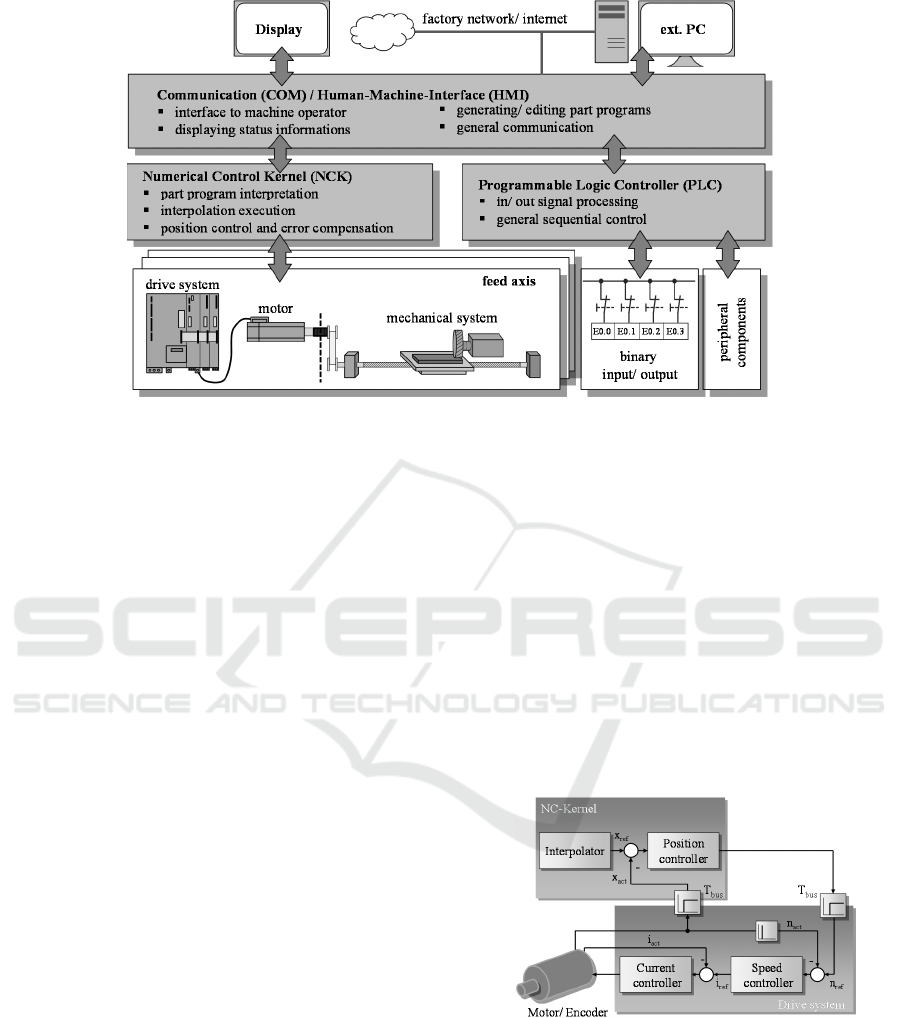
Figure 1: Structure of a typical computerized numerical control (Hellmich et al., 2016).
field devices (e.g. sensors, actuators), the interfaces
to the corporate network, which have lower or no
real-time requirements, should be mentioned in
particular (Weck and Brecher, 2006).
Consequently, the main goal of the paper is the
utilization of these interfaces to establish a
consistent information chain from the feed drives via
the CNC to the cloud. This forms the basis for
control loop-based monitoring methods. At the
beginning, an analysis of modern control systems
including the underlying communication channels
will be carried out (section 2). Subsequently, a novel
systematic approach for an automatic drive data
acquisition is presented (section 3). Section 4 is
focused on the machine-level integration of the
proposed method using an industrial embedded
system available on the market. By implementing an
exemplary identification algorithm, the functionality
of the system is validated and an outlook for future
developments is provided.
2 CONTROL OF MACHINE
TOOLS
In the field of machine tools, a higher-level machine
control is needed to realize an automated production
process. This superordinate control can usually be
assigned to the class of computerized numerical
controls. As shown in figure 1, the structure of such
a CNC can be subdivided into three essential
functional components. The COM part, also referred
to as the Human Machine Interface, allocates the
interface between the operator and the controller and
contains all operating, display and communication
functions. The PLC part is used to adapt the CNC to
the respective machine type. Structurally, it
corresponds to a programmable logic controller and
is utilized for signal processing of binary inputs and
outputs as well as for coupling various peripheral
components. In addition, the user has the
opportunity to integrate own specific functions. The
numerical control kernel realizes the main
functionality of the machine tool control like path
control, interpolation and the associated generation
of the motion setpoints. Typically, the position
control of the subordinated axes is also implemented
in the NC-Kernel.
Figure 2: Separation of the cascaded servo control in
electromechanical axes.
Whereas the data exchange of the controller
internal components usually is realized via shared
memory areas (dual-port RAM) (Siemens, 2010),
industrial established fieldbus systems are common
for the communication with the drive-internal
control units. These systems are usually based on a
specific communication protocol, which is divided
ICINCO 2018 - 15th International Conference on Informatics in Control, Automation and Robotics
390
into a cyclical and a user-specific, acyclical part
(Profibus, 2006). Within the cyclical part, all
parameter values relevant for the axis control (e.g.
speed set point value, actual position value) are
exchanged equidistantly in form of telegrams. Due
to the classification of the control loops in the
presented topology, not all control variables are
transmitted from the drives to the control system by
default. This can be partially avoided by expanding
the predefined telegrams with the desired values
(Siemens, 2011a). A second, acyclical data channel
can be used for diagnostic purposes or the
parametrization of the drives. By using proprietary
read/ write services, a user-specific data exchange
between the CNC and the drives can be
implemented. This forms the basis for the proposed
data management system in the following section.
3 SMART DATA MANAGEMENT
BASED ON DRIVE DATA
In this section, the novel data management system
with special focus on the provision of high-
frequency drive signals will be presented. The
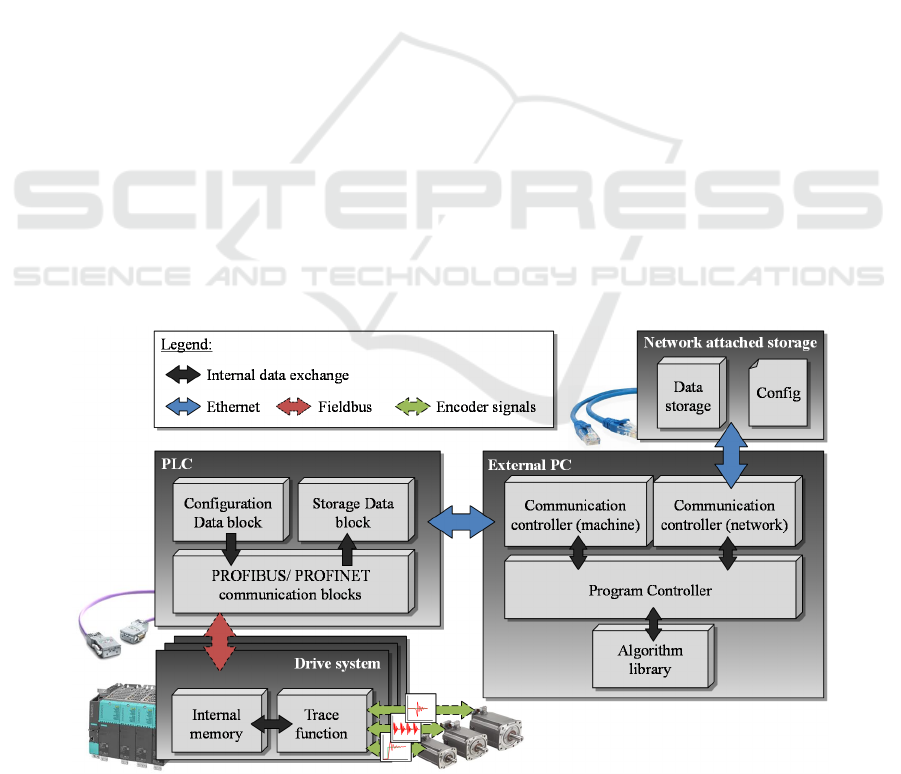
overall procedure (figure 3) is divided into two main
subsystems:
• A control-internal part, based on the fieldbus
communication between the drives and the
CNC and
• A control-external part, which includes the
necessary communication functions as well as
algorithms for data storage and aggregation
3.1 Drive Data Acquisition based on
Controller-Internal Functions
Due to the high system clock, only the drive-side
control modules are capable to record equidistant
sampled drive data with the required high
frequencies. For this purpose, the manufacturers of
modern drive systems (e.g. Siemens Sinamics S120)
already offer pre-installed measuring functions
(trace-function), which are located directly in the
control unit. This control unit works with a base
clock of 8 kHz and thus meets the requirements of
control loop-based monitoring methods (Siemens,
2011b). The trace function is primarily controlled
during the machine commissioning phase via a
corresponding engineering system. However, it is
also possible to implement a remote control of this
trace tool through dedicated list parameters.
The access to these parameters can be
implemented with the already mentioned read/ write
services of the PROFIBUS or PROFINET
connection. Targeted utilization in form of a state
machine allows an automated recording from the
PLC part of the control. The basic functional process
is illustrated in figure 4. First, the essential recording
parameters (signals, recording cycle, duration, etc.)
are parameterized in a configuration data block in
Figure 3: Structure of the drive based data management system.
Data Management System for Drive-based Smart Data Services - A Pratical Approach for Machine-Internal Monitoring Applications
391
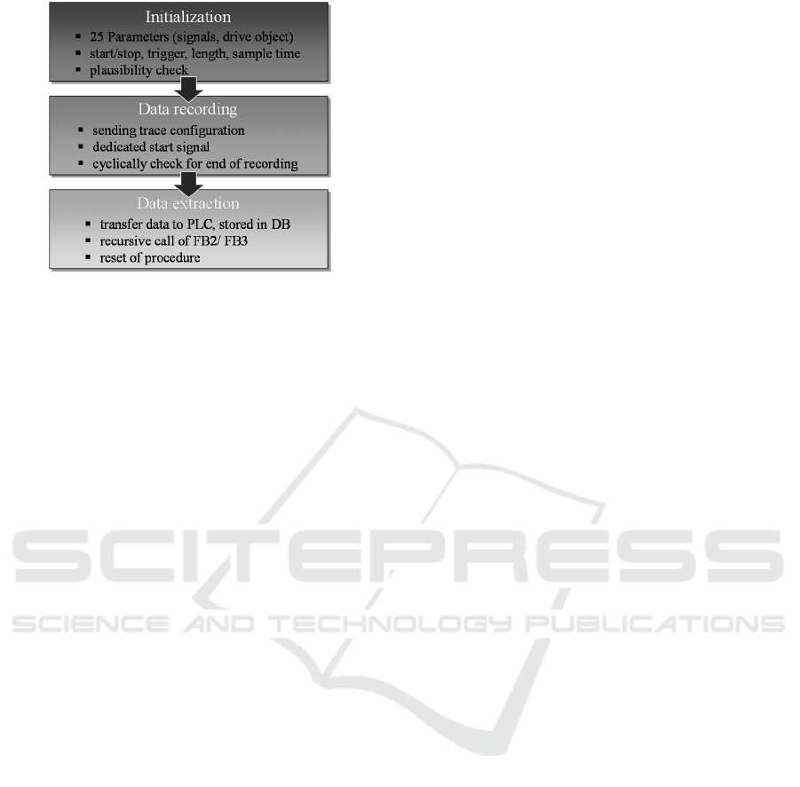
Figure 4: Sequential scheduling of control internal drive
data acquisition.
the PLC part of the CNC. The transfer of the
configured data to the drive control unit is
implemented via the function block FB2, which is
part of the default PLC-configuration. Subsequently,
the recording in the drive system is started
immediately or after a specific trigger condition
occurs (e.g. motor torque exceeds a configured
value). After completing the measurement, the
signals are stored in dedicated data blocks in the
PLC. The recorded signals are transferred via
cyclical calls of the function block FB 3. Due to
manufacturer-side limitations the signals are
transmitted in packages of eight values each. Further
details on the procedure and the underlying
functions are described in detail in (Hellmich et al.,
2016).
In comparison, the procedure described there
was restructured for an utilization in the intended
overall scenario. All parameters have been
integrated into a multi-instance function block,
which serves as the basis for the external access and
offers benefits in terms of memory utilization and
computing power.
3.2 Automatic Data Extraction and
Processing
After transferring the measured values to the PLC, a
central storage and enhancement of the
informational value in the sense of so-called Smart
Data Services is intended. Due to the limited
memory capacity and the cycle time dependent on
the program scope, this part of the CNC is not
suitable for permanent storage or further signal
processing.
As mentioned in section 2, however, modern
control systems have the standard possibility of the
integration into the company-internal Ethernet
network and thus to realize the coupling of a
personal computer with sufficient computing power.
There are various software interfaces already
available on the control side, for example to transmit
centrally generated part programs or for remote
maintenance. As part of the overall concept shown
in figure 3, an Ethernet-based software tool called
Snap7 has been determined, which provides the
essential functions for a bidirectional data exchange
between the PLC and external computing
technology in a corresponding library (Nardella,
2015). In addition to preinstalled communication
functions, various options for implementing
personalized read and write requests are included.
The novel created software application works
according to the client-server principle and thus
allows a data exchange between the machine control
and the connected computing technology. The
particularly developed program was designed to be
scalable in order to prospectively enable the support
of other control manufacturers without extensive
adjustments.
Functionally, a distinction can be made between
three essential components. An algorithm library
(module “calculations”) accommodates all functions
for the further processing of the logged drive data to
the mentioned control loop-based Smart Data
Services. This also includes the algorithm-specific
parametrization of the trace function. All required
communication functions were implemented in so-
called communication controllers. Their task is the
control-side access and thus the transmission of the
trace parameters and the recorded data. On the other
hand, additional communication partners such as the
central server for data storage are included. The
coordination of communication and calculation is
handled by a central process control whose basic
structure is illustrated in figure 5.
At the beginning, a machine-specific configuration
file located on the central server is loaded which
contains all required parameters. Subsequently, the
parametrization of the control-internal data
recording is initialized. After the extraction of the
data stored in the controller, the calculation of the
respective Smart Data Service and a cloud-based
backup of the results for further analysis (e.g. trend
analysis, data mining) as well as their visualization
take place.
ICINCO 2018 - 15th International Conference on Informatics in Control, Automation and Robotics
392
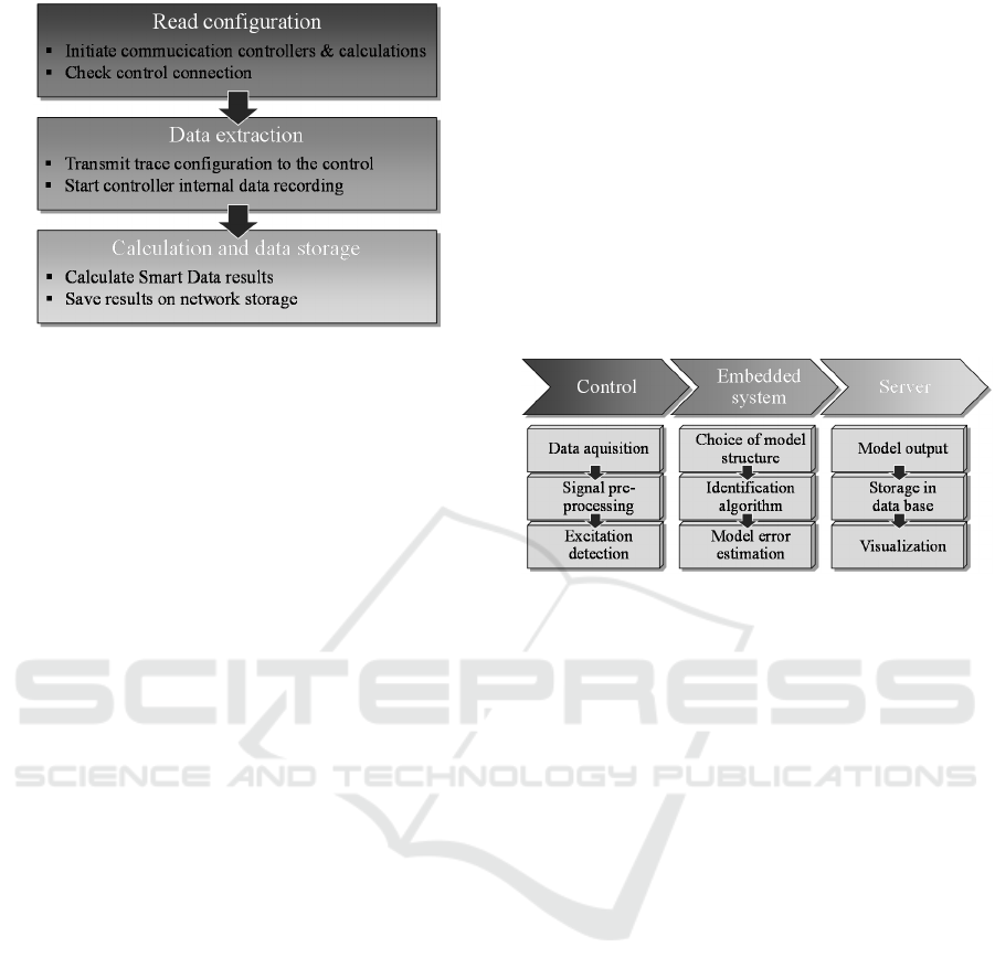
Figure 5: Sequential scheduling of control external data
processing.
4 HARDWARE-
IMPLEMENTATION AND
FUNCTIONAL VALIDATION
In this section, the previously presented method is
integrated in an exemplary machine control using
an industry-standard embedded system and is
validated by utilization of an exemplary
identification algorithm.
For control external implementation, a scalable,
Linux-based computing system called Revolution
Pi developed by Kunbus was defined. Its main
component is a multi-core processor which is
architecturally based on a conventional Raspberry
Pi. The core module is already installed in a rugged
profile rail housing by the manufacturer and meets
all standardized requirements for the industrial
utilization of programmable logic controllers. In
addition to simple control cabinet integration, it is
also possible to connect various gateways, for
example for the communication via customary bus
systems or in form of digital and analog input and
output modules. The data exchange with the CNC
is realized via an Ethernet connection as explained
in the previous section. Due to the limited memory
capacity of the embedded system (4 GB), the
configuration of the procedure and storage of the
results is located on the central server. In addition,
the controller-internal data acquisition was
integrated in the PLC part of the control.
For the experimental verification, a method for
a noninvasive identification of control plant
parameters developed by (Hellmich, 2014) was
selected and adapted for industrial purposes. This
modular method estimates actual values for total
moment of inertia and friction torque of the
considered axis based on high sampled drive
signals, in particular actual motor speed and torque.
First of all, a conceptual classification of the
underlying modules of the procedure into the
extended control architecture was carried out.
Thus, a part of the modules (data acquisition, signal
pre-processing, excitation detection) was
implemented within the control, whereas the
majority of the calculations are performed on the
Revolution Pi. The division of the modules into the
individual components is illustrated in figure 6. For
more detailed information of the underlying method
see (Hellmich, 2014) or (Schoeberlein, 2016).
Figure 6: Integration of the non-invasive identification
algorithm into the novel data management system.
All subcomponents were integrated on a three-
axis test rig with a commercially available
Siemens-CNC (Sinumerik 840D sl). In order to
validate the method, an exemplary selected feed
axis was excited with a sinusoidal velocity profile.
The actual values of the recorded signals for motor
speed and torque in x-direction are shown in figure
7. As it can be seen in the enlarged view, the
recording was performed with a sampling clock of
500 µs. A measurement of these values with such a
high resolution is only feasible in the drive-internal
control modules. In addition to the high-frequency
signal recording, an exemplary parameter
identification was performed based on the
measured signal profiles. A comparison of the
calculated moment of inertia and friction torque
based on construction data as well as experimental
preliminary investigations shows a good agreement
(table 1). From this it can be concluded that the
combination of Smart Data Management System
and drive-based Smart Data Services located in a
fully-integrated embedded system is suitable for
machine-internal monitoring functions.
Data Management System for Drive-based Smart Data Services - A Pratical Approach for Machine-Internal Monitoring Applications
393
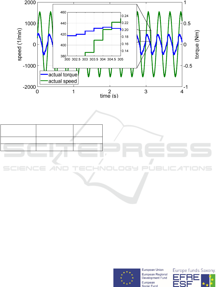
Figure 7: Recorded values for actual motor speed and torque.
Table 1: Comparison of the identification results with
theoretical calculations.
Calculation
results
Identification
results
Δ [%]
J
x
= 34.46 kgm² J
x
= 34.67 kgm² J
x,Δ
= 0.6
T
R,x
= 0.051 T
R,x
= 0.057 T
R,x, Δ
= 10.5
5 CONCLUSIONS
In this paper, current research results in the field of
drive-based Smart Data Services for production
systems were presented. In addition to the
establishment of a control-internal data management
system for the acquisition of control loop data, the
machine infrastructure was selectively expanded by
integrating an embedded system available on the
market. This allows the machine-level processing of
cyclical logged drive data and their informational
enhancement to significant characteristic values.
Furthermore, a global data store has been set up,
which ensures the availability of all measured
signals as well as calculation results and can serve as
a basis for further applications.
The core idea of the research project is the
manufacturer-independent networking of production
systems as well as a central data provision and
further processing in the sense of Smart Data
Services. For this reason, in the next step,
possibilities for connecting further control
manufacturers (e.g. Heidenhain) and an associated
drive data acquisition has to be realized. Due to the
architectural differences in the control systems, new
approaches are needed here. Subsequently, further
control loop-based monitoring algorithms should be
implemented and investigated for their suitability by
long-term tests. At this point, the earlier mentioned
control-loop based algorithms as performance index
(Quellmalz et al., 2014) or Prony-Analysis
(Schoenherr, 2012) are eligible to improve the
understanding of the control behavior parallel to the
process. Furthermore, it would be conceivable to use
the results directly to adapt the drive control
parameters online and thus react to changing
circumstances. Due to the conceptual design of the
data management system, in addition to the
extraction of the drive data their targeted adaption is
feasible.
The conclusion is the expansion of the data
infrastructure, for example considering the global
availability within the network storage or the parallel
recording of machine and additional sensor data.
Subsequent correlation and pattern analysis will
provide new insights into the state of production
systems and contribute to autonomous, cyber-
physical systems in the sense of Industry 4.0.
ACKNOWLEDGEMENTS
Funded by the European Union (European Social
Fund) and the Free State of Saxony.
time (ms)
torque (Nm)
speed (1/min)
ICINCO 2018 - 15th International Conference on Informatics in Control, Automation and Robotics
394

REFERENCES
Bindu, B., Vinod, B., (2015). Measurement of Cutting
Forces in CNC Turning Centers: A Review.
International Journal of Mechanical Engineering,
3(5), pp. 77-87.
Hellmich, A., (2014). Nichtinvasive Identifikation von
Regelstreckenparametern für elektromechanische
Achsen. PhD Thesis, Chemnitz University of
Technology.
Hellmich, A., Quellmalz, J., Schoeberlein, C., Schlegel,
H., Putz, M., (2016). Drive Data Aquisition for
Controller Internal Monitoring Applications, Journal
of Machine Engineering, 13(2), pp. 82-94.
Matsabura, A., Ibaraki, S., (2009). Monitoring and Control
of Cutting Forces in Machining Processes: A Review.
International Journal of Automation Technologies,
3(4), pp. 445-456.
Nardella, D., (2015). SNAP7 1.4.0: Reference manual.
Viewed 27 April 2018, http://snap7.sourceforge.net.
Neugebauer, R. (eds.), (2012). Werkzeugmaschinen –
Aufbau, Funktion und Anwendung von spanenden und
abtragenden Werkzeugmaschinen. Springer Verlag,
Berlin.
PROFIBUS Nutzerorganisation e.V., (2006). Profile
Device Technology PROFIDRIVE: Technical
Specification for PROFIBUS and PROFINET Version
4.1. PROFIBUS Nutzerorganisation e.V., Karlsruhe.
Quellmalz, J., Schlegel, H., Rehm, M., Neugebauer, R.,
(2014). Influence analysis on the model comparison
performance index for servo drive control.
Proceedings of the 16th International Conference on
Mechatronics – Mechatronika 2014. (eds. Brezina, T.,
Maga, D., Stefek, A.), Brno, Brno University of
Technology, pp. 242-247.
Schoeberlein C., (2016). Konzept und beispielhafte
Implementierung einer nichtinvasiven Identifikations-
routine an Werkzeugmaschinen. Master Thesis,
Chemnitz University of Technology.
Schoenherr, R., (2012). Regelkreisüberwachung mecha-
tronischer Antriebssysteme. PhD Thesis, Chemnitz
University of Technology.
Siemens AG, (2010): SINUMERIK 840D sl / 828D Basic
Functions Function manual. Siemens AG, Nürnberg.
Siemens AG, (2011). Simatic S7-300 – Connection of the
SINAMICS S120 to the Technology CPU. Siemens
AG, Nürnberg.
Siemens AG, (2011). SINAMICS – S120 Commissioning
manual. Siemens AG, Nürnberg.
Teti, R., Jemielniak, K., O’Donnell, G., Dornfeld, D.,
(2010). Advanced monitoring of machining opera-
tions. In: CIRP Annals – Manufacturing Technology,
59(2), pp. 717-739.
Weck, M. (eds.), Brecher, C., (2006). Werkzeugmaschinen
3 – Mechatronische Systeme, Vorschubantriebe,
Prozessdiagnose. Springer Verlag, Berlin.
Data Management System for Drive-based Smart Data Services - A Pratical Approach for Machine-Internal Monitoring Applications
395
