
Distributed Energy Resource ICT Reference Architecture
Distributed Control Architecture for Hardware Limited Internet of Things DERs
Bo Petersen
1
, Henrik Bindner
1
, Bjarne Poulsen
2
and Shi You
1
1
DTU Electrical Engineering, Technical University of Denmark, Anker Engelundsvej 1, 2800 Lyngby, Denmark
2
DTU Compute, Technical University of Denmark, Anker Engelundsvej 1, 2800 Lyngby, Denmark
Keywords: Smart Grid, Internet of Things, Drivers, Native Communication, Historical Data, Real-Time Data, Predicted
Data, Communication Standards, IEC 61850, OpenADR, Serialization, Discovery Service, Network
Discovery, Service Discovery, Communication Negotiation, Communication Middleware, Capability
Discovery, Generic Interface, Access Control, Tracker Service, Administration Interface, Plug ‘N’ Play,
Application Launcher, Automatic Configuration, Self-Healing, Topology Detection.
Abstract: For Distributed Energy Resources to participate in the grid, and help solve the problems of unreliability and
inefficiency, caused by weather dependent, and distributed energy resources, they must have a processing
unit, data connection, and an ICT architecture. The aim of the paper is to describe the software components
of the ICT architecture, thereby improving the design of scalable ICT architectures for automatically
controlled DERs. Future plug ‘n’ play software components that improve the scalability and eases the
development of such ICT architectures are also described in the paper. The ICT architecture should be scalable
to many different types of DERs with minimal effort and should enable control by automated generic
controlling entities. The ICT architecture primarily consists of three layers, the driver layer that uses native
communication to talk to the unit hardware, the data layer that supplies historical data, real-time data, and
future prediction to the communication layer, which is responsible for talking to the controlling entities. With
the plug ‘n’ play extension components which adds the application launcher, automatic configuration, self-
healing and topology detection.
1 INTRODUCTION
With the increasing amount of Renewable Energy,
the power grid faces challenges caused by the
intermittent production of energy by weather
dependent energy resources like solar panels and
wind turbines, and by the increasing share of
distributed energy resources.
To handle these challenges of power grid
reliability and power use efficiency, the Distributed
Energy Resources (DERs), both generation and
consumption units, must participate in the operation
of the power grid.
This participation can be achieved with economic
incentives for the owners and must go beyond having
the owners control the DERs manually to move
production, with aggregators and local controllers
that control the DERs automatically, either by having
these controlling entities participate in energy and
flexibility (Zhang, 2014) markets or by using price
signals.
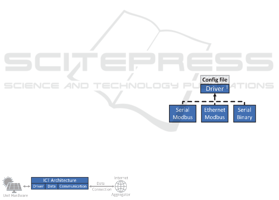
The necessary parts to enable automatic control
by controlling entities is a processing unit, data
connection and an ICT architecture consisting of
software components (figure 1).
Figure 1: DER parts.
The focus of the paper is not the controlling
entities, which could be located on the DERs, but the
software components of the ICT architecture
necessary for automatic control.
The aim of the paper is to describe the software
components, in enough detail to give the reader an
overview of what a scalable DER ICT architecture
should contain. Not all components are necessary for
Petersen, B., Bindner, H., Poulsen, B. and You, S.
Distributed Energy Resource ICT Reference Architecture.
DOI: 10.5220/0006701201990205
In Proceedings of the 7th International Conference on Smart Cities and Green ICT Systems (SMARTGREENS 2018), pages 199-205
ISBN: 978-989-758-292-9
Copyright
c
2019 by SCITEPRESS – Science and Technology Publications, Lda. All rights reserved
199
every use case, but they are necessary for a generic
architecture.
The plug ‘n’ play section describes the application
launcher and possible extensions to the ICT
architecture.
The state of the art for this area is a collection of
scientific articles defining and aggregating the
requirements of ICT architectures for the Smart Grid
or Smart Homes, whereas this paper is specific to the
ICT architecture for DERs, and proposes scalable
solutions to fulfill the requirements for a DER ICT
architecture (Rohjans, 2012) (Zaballos, 2011) (Kok,
2009).
The hypothesis of the paper is that with the right
components a scalable DER ICT architecture can be
constructed that works for all DERs, with a minimal
amount of work for each different DER in the form of
configuration files, and enables automated generic
controlling entities.
This is a conceptual paper with ideas and concept
for building a DER ICT architecture. A prototype was
created including many of the software components
of the paper, not including the plug ‘n’ play section
components, except for the application launcher. The
paper does not follow the IMRaD structure but the
“Big Book” paper structure (Best Custom Writing,
2017), as the paper does not present experimental
results, and this structure, therefore, more accurately
presents the content of the paper.
2 MODEL
The ICT architecture model consists of three layers,
the driver, data and communication layers (figure 2).
While only one instance of the data layer and
communication layer is necessary, multiple drivers
are needed to talk through multiple types of native
communication to the unit hardware. It could also be
the case that one driver talks to the unit hardware of
multiple units, e.g. one inverter for multiple solar
panels.
Figure 2: ICT architecture layers.
The ICT architecture, therefore, keeps the data
separated into multiple virtual devices, that each
represents a logical unit.
The driver layer is responsible for native
communication with the unit hardware, converting
measurements into a generic format, and supplying it
to the data layer, while also receiving control
commands from the data layer, and sending them to
the unit hardware.
The data layer gets measurements from the driver
layer, stores it, provides the past, current and
predicted future measurements to the communication
layer and relays control commands to the driver layer.
The communication layer supplies measurements
from the data layer to controlling entities through
external network communication and receives control
commands from the controlling entities and relays
them to the data layer. It also converts the
measurements and control commands to
communication standards.
3 DRIVER LAYER
The driver layer is the hardest layer to make generic
and will always be partially specific to the unit
hardware.
The basic idea is to create drivers that are specific
to the types of native communication required to talk
to different unit hardware, like Modbus over ethernet,
and then implement a common interface that talks to
the data layer, pushing new measurements and
receiving control commands (figure 3).
Figure 3: Driver hierarchy.
The native communication specific driver is then
combined with a configuration file that has a unit
hardware specific map, which maps the native
communication addresses to generic value types,
names, and paths for communication standards. The
paths are not used by the driver layer, but by the
communication layer to map the measurements and
control commands to communication standards.
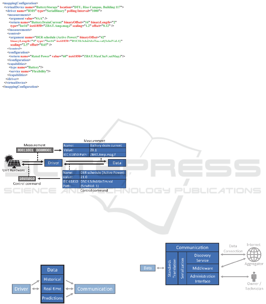
The configuration file with the unit hardware
specific mappings should be in a format which is
human-readable and can be deserialized, like XML,
JSON or YAML (Listing 1).
The configuration file should also contain native
communication information, like the serial port
number and baud rate, unit hardware information like
the maximum polling interval and maximum current,
SMARTGREENS 2018 - 7th International Conference on Smart Cities and Green ICT Systems
200
and transformation information like the scaling and
offset of measurements.
Listing 1: Example of a configuration file in XML.
Essentially the driver layer exchanges bytes with
the unit hardware converts the bytes using the
configuration file map, and exchanges measurements
and control commands with the data layer (figure 4).
Figure 4: Driver translation example.
4 DATA LAYER
The data layer has three components for historical
data, real-time data and data predictions, which are
responsible for the past, current and future
measurements respectively (figure 5).
Figure 5: Data layer components.
The historical component has a local data store
(e.g. database) that persistently stores the
measurements it receives from the driver, and then
provides them to the communication layer, on
request.
The real-time component keeps current
measurements from the driver available for quick
access, by storing them in memory, and relays them
to the communication layer, so they can be sent to
subscribers. It also relays control commands to the
driver layer from the communication layer.
The predictions component uses data from the
historical component and possible a meteorological
station (which if it is external, requires retrieval of
measurements through the communication layer), to
provide predictions for future measurements.
The prediction uses machine learning to train on
the historical data, to predict the future measurements
of the unit hardware, and should take the historical
and future metrological measurements into account
for weather dependent DERs. It should also take
control commands in the form of schedules into
account.
For Smart Grid research laboratories and other
experimental setups, the prediction could be used to
simulate the unit hardware, if historical data is
available.
5 COMMUNICATION LAYER
The communication layer consists of a standards
translation component that converts the data to
communication standards and passes it on to a
serialization component that converts the data to a
format that can be transmitted over a network, which
is what the middleware component does.
Additionally, a discovery service component
provides discovery and negotiation mechanisms, and
the administration interface component allows the
owner and technicians to control and configure the
DER (figure 6).
Figure 6: Communication layer components.
5.1 Standards Translation
The standards translation component translates the
data from the generic representation to the format of
a communication standard, like the IEC 61850
Distributed Energy Resource ICT Reference Architecture
201
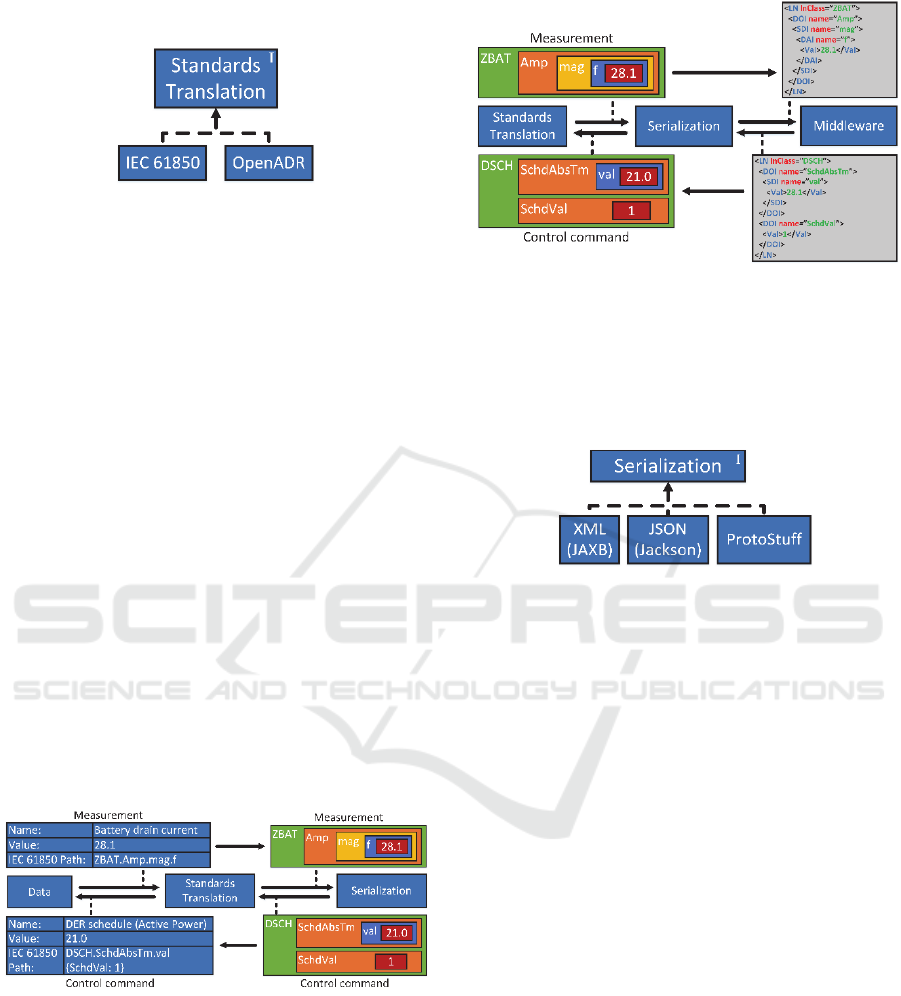
(Machiewicz , 2006), OpenADR (McParland , 2011)
or another future standard (figure 7).
Figure 7: Standards translation hierarchy.
The standards translation component is
independent of the data layer to keep the data layer
from being tied to a particular communication
standard while enabling the DER to communicate
with controlling entities using multiple
communication standard formats.
The reason multiple communication standards
must be used is because no one of them covers all use
cases. IEC 61850 describes the unit hardware by
physical components which is good for diagnostics,
while OpenADR describes it by the services it
provides, without providing a specific data model,
which is good for ancillary services like voltage
control and load shifting but still lacks a specific data
model.
This requires future standards to describe the
information missing from these standards. This
includes capability and requirement descriptions,
which are part of the ICT architecture data model.
Figure 8 shows how the generic representation of
the battery current is translated to an IEC 61850
ZBAT battery description, and how an IEC 61850
DSCH active power schedule is converted to a
generic representation.
Figure 8: Standards translation example.
5.2 Serialization
The serialization component converts the data from
the memory representation of the communication
standard format to a string or binary format, that can
be transmitted over a network (figure 9).
Figure 9: Serialization example.
The serialization format and library used, strongly
affects the performance of the external
communication to the controlling entities, and
depends on the unit hardware and data connection
(figure 10).
Figure 10: Serialization hierarchy.
The performance and characteristics of a broad
range of serialization formats and libraries are
covered in an earlier paper titled “Smart Grid
Serialization Comparison” (Petersen, 2017), which
concludes that JSON has better performance than
XML, while being human-readable, binary serializers
have better performance than string serializers, and
ProtoBuf (ProtoStuff), and ProtoStuff have the best
performance.
It is, therefore, important to be able to choose the
right serialization for each use case and have the
serialization be interchangeable instead of being tied
into the middleware.
5.3 Discovery Service
The discovery service uses a separate communication
mechanism to communicate with controlling entities
prior to the establishment of a middleware
communication channel with better performance.
This could be an overlay network, that makes internet
scale network discovery possible.
The discovery service is responsible for providing
passive network discovery, service discovery, and
communication negotiation (figure 11).
SMARTGREENS 2018 - 7th International Conference on Smart Cities and Green ICT Systems
202
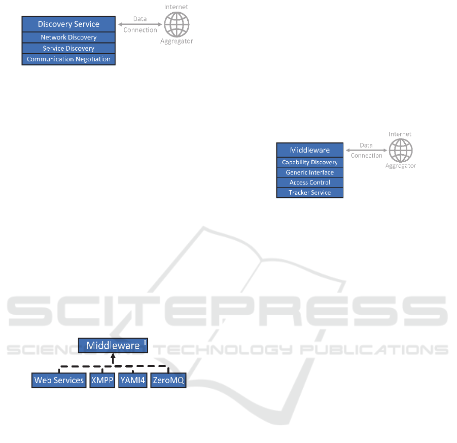
Figure 11: Discovery service subcomponents.
The network discovery subcomponent is
responsible for responding to network discovery
messages, to allow controlling entities to find the
DER.
The service discovery subcomponent acts as a
proxy for the middleware by being available on a
fixed predefined port, and by providing the
middleware ports, allowing middleware to change
ports, and for middleware to be added.
The communication negotiation subcomponent
lets controlling entities pick which middleware,
serialization, and communication standard will be
used for the communication.
5.4 Middleware
The middleware component enables multiple types of
middleware that all implement the same middleware
interface, that enables them to be used
interchangeably (figure 12).
Figure 12: Middleware hierarchy.
Different middleware have different throughput
and latency performance, depending on the
processing unit and data connection. Therefore, and
because different controlling entities might support
different middleware, different middleware should be
used depending on the use case.
The details of the differences in performance and
characteristics for a broad range of middleware is
covered in an earlier paper titled “Smart Grid
Communication Middleware Comparison” (Petersen,
2017), the performance of serialization combined
with middleware is covered in an earlier paper titled
“Smart Grid Communication Comparison” (Petersen,
2017), and the performance of combinations of
middleware and serialization, with different
processing units and data connections, is covered in
an earlier paper titled “Smart Grid Communication
Infrastructure Comparison” (Petersen, 2017).
These papers conclude that YAMI4 and ZeroMQ
have the best combination of performance and
characteristics, while ICE and WAMP have
satisfactory performance and characteristics.
Considerations for the choice of processing units and
data connections are also covered, but there is not one
perfect choice.
The middleware component has four
subcomponents that work through the middleware,
the capability discovery, generic interface, access
control and tracker service (figure 13).
Figure 13: Middleware components.
5.4.1 Capability Discovery
The capability discovery subcomponent provides a
DER component description (IEC 61850), a type
description, service descriptions (OpenADR), and
capabilities descriptions (which could, for instance,
be the flexibility of the DER or how much it can
change the power frequency).
5.4.2 Generic Interface
The generic interface subcomponent provides a set of
generic interfaces for data acquisition and control,
which are independent of DER unit hardware.
5.4.3 Access Control
Allowing the aggregator to control the DER, requires
that the owner uses a password printed on the DER to
log into the UI, and enters an aggregator key, received
when signing a contract with the aggregator.
Or by having a centralized system where the DER
and aggregator register themselves, with a DER key
being given to the aggregator when the owner signs a
contract with the aggregator. The key is then retrieved
by the aggregator from the centralized system and
given to the DER to authenticate the aggregator.
The problem gets a lot harder when DERs need to
cooperate to solve power system issues, such as
providing voltage control. This requires a distributed
trust system that helps a DER to decide whether it
should trust requests from local controllers.
The problem of who to trust in a distributed
system is important to solve because of cyber security
concerns about how a few computers could trick
Distributed Energy Resource ICT Reference Architecture
203

many DERs into believing that they should perform
actions to help the power grid, while actually
resulting in the DERs crashing the power grid.
This is just one of the cyber security concerns that
must be solved with the rise of the Smart Grid and the
Internet of Things.
5.4.4 Tracker Service
The tracker service broadcasts DER alarm and events
to subscribing entities, such as aggregators, local
controllers, visualizations, and auditing entities. This
could be a solar panel that sends an event, that it has
now started production because the amount of sun
irradiation has gotten large enough or a wind turbine
that sends an alarm message because the rotation
speed has gotten too fast, because of the wind speed.
It also keeps a log of previous communication
requests, in the form of control commands and
requests for measurements, which it provides to
external entities.
5.5 Administration Interface
The administration interface should provide a
graphical interface through a browser to the owner,
which provides statistical measurement information,
allows the owner to manually control the DER,
provides access control administration, and allows a
technician to change the configuration of the DER.
6 PLUG ‘N’ PLAY
The aim of a plug ‘n’ play extension to the ICT
architecture is to have little or no configuration, and
as little maintenance as possible.
6.1 Application Launcher
When the ICT architecture is started, the application
launcher launches all the fixed components but leaves
the interchangeable components, the drivers,
serialization, standards translation, and middleware.
It then uses the hardware configuration file to
determine which driver components should be
launched and does so.
It then provides the available interchangeable
components to the discovery service and waits for it
to relay the requested standards translation,
serialization, and middleware, and launches them on
demand, which is a result of the communication
negotiation performed by the discovery service.
The application launcher has fixed references to
the fixed components and uses reflection to get
references to the interchangeable components. It then
uses dependency injection to glue the components
together to the ICT architecture, by sharing the
references with the components.
This allows the application launcher to shut down
components that are not being used, and launch
components on demand when they are requested.
6.2 Automatic Configuration
The simple, but time-consuming way to create
configuration files is to create them from
documentation which for the manufacturer might be
a small expense compared to creating the unit
hardware, but for a company creating a device to
connect to any type of DER might make the
difference between the project being viable or not.
To avoid spending the time to create a
configuration file, a piece of software could be
constructed that uses machine learning and
measurements from external measurement hardware
to reverse engineer the unit hardware specific map.
The external measurement hardware could be a smart
meter if the power system changes caused by the unit
can be isolated.
This would of cause not be capable of mapping
measurements that cannot be measured externally
like the temperature of the unit but could create a
partial map that might be enough for certain power
system ancillary services.
This could be taken one step further by having an
algorithm that cycles through the processing unit
ports (e.g. serial or ethernet), to determine which are
connected and then attempt to launch drivers with
different configuration information, to attempt to
establish a connection, but this would be a brute force
approach.
6.3 Self-Healing
By having a separation of components, the
controlling entities should be able to restart the
software components and could be able to attempt to
reset the unit hardware, in the event of a problem, by
initiating a self-healing service. However, this would
require, that the service mapping is defined in the
hardware configuration file.
Self-healing would also allow the controlling
entities to permanently change the power scaling and
offset of the system and configuration file.
Determining how to change the scaling and offset
would require the controlling entities to have a second
SMARTGREENS 2018 - 7th International Conference on Smart Cities and Green ICT Systems
204

source of measurements for the DER, which could be
a Smart Meter if the effects of the unit can be isolated.
6.4 Topology Detection
The idea is to provide information about the power
system topology to controlling entities, enabling them
to better solve local power system issues like voltage
or frequency control.
The topology detection could be part of the
controlling entities by comparing measurements of
multiple DERs to determine their power system
distance.
Alternatively, a more active approach could be
used by having a DER perform slight changes to the
power system, like changing the frequency a little bit
and having other DERs attempt to detect the signal,
showing which DERs are closely connected, like
echolocation. This approach would use the same
technology as Power Line Communication and would
have to be part of the DERs.
7 CONCLUSIONS
An ICT architecture with the components described
in the paper, along with the plug ‘n’ play extensions,
would enable controlling entities to automatically
control DERs, with little to no work done to scale to
a potentially unlimited number DER with different
unit hardware, also requiring little to no maintenance
because software problems and hardware calibration
problems.
Future work should be done on network discovery
that works over the internet and is tailored for Smart
Grid applications, by taking unit location and
characteristics into account.
Current communication standards should be
extended to describe unit capabilities, and predefined
data models for service descriptions, as oppose to the
current version of OpenADR.
In addition to the many cyber security challenges
that need to be solved for the Internet of Things, a
mechanism for managing trust between computers in
a distributed system is essential for the future Smart
Grid.
ACKNOWLEDGEMENTS
Sponsored by the project, PROActive INtegration of
sustainable energy resources enabling active
distribution networks (PROAIN).
REFERENCES
Zhang, C., Yi, D., Nordentoft, N. C., Pinson, P., Østergaard,
J., 2014. FLECH – A Danish market solution for DSO
congestion management through DER flexibility
services, Journal of Modern Power Systems and Clean
Energy, 2nd ed., vol. 2, pp. 126-133, 2014.
Rohjans, S., Dänekas, C., Uslar, M., 2012. Requirements
for smart grid ICT-architectures, ISGT Europe, 2012.
Zaballos, A. Vallejo, A., Selga, J. M., 2011. Heterogeneous
communication architecture for the smart grid, IEEE
Network, 5th ed. vol. 25, pp. 30-37, 2011.
Kok, K., Karnouskos, S., Nestle, D., Dimeas, A., Weidlich,
A., Warmer, C., Strauss, P., Buchholz, B., Drenkard, S.,
Hatziargyriou, N., Lioliou, V., 2009. Smart houses for
a smart grid, CIRED, 2009.
Best Custom Writing, 2017. Is the IMRAD model right for
you, [Online], Available: http://www.bestcustom
writing.com/blog/writing-in-general/is-the-imrad-
model-right-for-you/. [Accessed 21 04 2017].
Machiewicz, R. E., 2006. Overview of IEC 61850 and
Benefits, IEEE PES Power Systems Conference and
Exposition, Atlanta, GA, pp.623-630, 2006.
McParland, C., 2011. OpenADR open source toolkit:
Developing open source software for the Smart Grid,
IEEE Power and Energy Society General Meeting, San
Diego, CA, pp. 1-7, 2011.
Petersen, B., Bindner, H., Poulsen, B., You, S., 2017. Smart
Grid Serialization Comparison, SAI Computing
Conference, London, 2017.
Petersen, B., Bindner, H., Poulsen, B., You, S., 2017. Smart
Grid Communication Middleware Comparison,
SmartGreens, Porto, 2017.
Petersen, B., Bindner, H., Poulsen, B., You, S., 2017. Smart
Grid Communication Comparison, ISGT Europe,
Torino, 2017.
Petersen, B., Bindner, H., Poulsen, B., You, S., 2017. Smart
Grid Communication Infrastructure Comparison,
ICPES, Toronto, 2017, in press.
Distributed Energy Resource ICT Reference Architecture
205
