
Software Development Process Supported by Business Process Modeling
An Experience Report
Olga Vega
1
, Helga Duarte
2
and Jaime Chavarriaga
3
1
Universidad de los Llanos, Villavicencio (Meta), Colombia
2
Universidad Nacional de Colombia, Bogot
´
a, Colombia
3
Universidad de los Andes, Bogot
´
a, Colombia
olvegam@unillanos.edu.co, hduarte@unal.edu.co, ja.chavarriaga908@uniandes.edu.co
Keywords:
Software Development Process, Business Process Modeling.
Abstract:
Understanding businesses and how they work can help software engineers build systems that really meet the
corresponding business goals. For instance, methods such as the Rational Unified Process (RUP) include activ-
ities to model a business before eliciting requirements. However, during our software development practice in
academic and ”real-life” projects, we found problems using these artefacts with stakeholders. Here we present
our experience on integrating BPMN (Business Process Modeling and Notation) diagrams with RUP, aiming
to improve the elicitation of software requirements. These diagrams appeared to be easier to understand by
stakeholders. The current paper discusses the challenges we faced in using RUP and the way in which we
integrate conceptual maps and BPMN into the process. In addition, we illustrate the changes using models
that reflect real project implementations realized by using this approach.
1 INTRODUCTION
Nowadays, software is a key element in business
strategies and processes. Very often organizations re-
quest new software aiming to improve their business
or contribute to their goals. Understanding the busi-
ness and how it works can help software engineers to
build systems that will really meet the expectations.
In the Universidad de los Llanos (Unillanos)
1
, we
have used RUP in academic and “real life” software
development projects. It is used not only in courses
related to software engineering but also in develop-
ment projects aimed to the university and other af-
filiated institutions. Faculty members and students
are usually involved in these projects trying to ap-
ply the concepts and models described in the theory
into real settings. However, after our experience in
several projects between 2010 and 2017, we have in-
tegrated Business Process Models, i.e., BPMN dia-
grams (OMG, 2011), into the RUP activities to im-
prove the business understanding by stakeholders and
developers.
This paper presents our experience using BPMN
diagrams to support activities for eliciting and spec-
1
The Universidad de los Llanos (Unillanos) is the
biggest public university in the eastern plains in Colombia
ifying software requirements. Here we present some
of the challenges we faces trying to use RUP to under-
stand business processes, and obtain agreements on
the corresponding software requirements. We present
our integration of BPMN and RUP and discuss some
lessons learned in multiple academic and “real-life”
software development projects.
The rest of this paper is organized as follows: Sec-
tion 2 describes our experience on several software
development projects and how we integrated BPMN
in this context. Section 3 presents the modifications
we made to RUP to integrate BPMN and Section 4
concludes the paper.
2 ELICITING REQUIREMENTS
FOR BUSINESS APPLICATIONS
Developing software to support business processes
implies an understanding of these processes. For in-
stance, the method we used, the RUP - Rational Uni-
fied Process -, includes activities to model the busi-
ness processes before eliciting the software require-
ments.
Eliciting requirements using RUP. In RUP, busi-
ness processes are analyzed using diverse artifacts:
242

(1) Each process is depicted using a BUCM - Busi-
ness Use-Case Model, i.e., by a circle and a set of
relationships to the diverse actors that participate. (2)
The activities in each process are specified using an
AD- Activity Diagram, i.e., a flowchart-like model
that represents the steps that comprise the process (Ja-
cobson et al., 1999). Finally, (3) Additional informa-
tion is specified in a glossary and a set of textual de-
scriptions and specifications.
Challenges using RUP. Although there are some
books and guides describing how to elicit require-
ments based on the models representing the processes
in RUP, we faced multiple challenges.
Using the glossary: our software engineers had
problems to write correctly the terms in the glos-
sary. Some times they wrote incorrect definitions or
assumed incorrectly that two terms were equivalent.
The problems were aggravated by users that refused
to read and correct glossaries with a large number of
terms.
Using the BUCMs: software engineers and stake-
holders had problems to review the BUCMs. These
models represent processes as use-cases without spec-
ifying an ordering of the tasks, inputs and outputs nei-
ther the people that perform the tasks. Many times
the stakeholders approved a BUCM because they rep-
resented steps in the process without noting missing
tasks or missing participants.
Using the ADs: finally, activity diagrams cannot
represent some elements important in the processes
such as escalations and deadlines. Software engineers
and stakeholders were able to use ADs to discuss on
the typical case of the process but failed to represent
there the exceptional flows.
Additionally, we found problems trying to create
a single set of models representing the business pro-
cesses. In many projects the stakeholders were sure of
the steps in the current process but not of the steps in
the process they want. In addition, we had to deal
with constant changes on the stakeholders, the do-
main’s experts, the involved legal regulations and/or
the software requirements. Many times, the models
combined elements of the current process with one or
more of the desired processes. It was hard, when a
change in a regulation or stakeholder occurred, to de-
termine which elements must be modified. Moreover,
some stakeholders did not receive well the ideas and
recommendations of the software engineers because
they believed that the software engineers did not un-
derstand the process because of these models.
Related Work. There are other methods and mod-
eling notations aimed to represent business process.
For instance, the BPMN - Business Process Model-
ing and Notation - is an OMG standard for “bridg-
ing the gap between process design and implementa-
tion”. Although business modeling can be done inde-
pendently of the software development, it is clear that
each process can benefit from the other.
There are studies that show a misalignment be-
tween the software applications and the business
processes of many organizations (Przybylek, 2014).
These studies describe, as a main reason, the lack
of methodology and rigor to determine the software
requirements from the business goals. Other stud-
ies (Sedelmaier and Landes, 2014) (Monsalve et al.,
2012) have shown the benefits of determining require-
ments based on the modeling of the business pro-
cesses that the software aims to support. Thereby, we
can find tools integrating business and software mod-
eling such as IBM Rational and Visual Paradigm.
3 OUR PROPOSAL
To overcome the mentioned problems we integrated
conceptual maps and BPMN diagrams into the Re-
quirements activities of the RUP.
Figure 1: Changed requirements activities.
Figure 1 shows the process starting when a client
requests a new software. Then, the project team
model the business and elicit the requirements. The
requirement specifications are later reviewed with the
client. If the client agrees, the process follows to other
phases such as analysis, design and implementation
(out of the scope of this paper).
3.1 Model Business
The main changes we made on the Business Modeling
sub-process were the artifacts produced, showed in
Figure 2. We complemented the glossary with a con-
ceptual map, and replaced the BUCM and AD by an
AS-IS business process model. In addition, once they
are built, the conceptual map and the business pro-
cess models are reviewed and modified directly with
the client.
Conceptual map: A conceptual map is a technique
to graphically represent the knowledge. The project
Software Development Process Supported by Business Process Modeling - An Experience Report
243

Figure 2: Model business sub-process.
team constructs a first version showing the concepts
and the relations between them such as they are under-
stood. Then, using a whiteboard the map is reviewed
and modified with the domain experts. The purpose
of this graphical artifact is to facilitate the concepts
review between the development team and the client,
and, in this way, contribute to an adequate communi-
cation in the project, as a result of talking in the same
terms.
BPMN AS-IS: The BPMN AS-IS represents the
current business processes. Developers create an ini-
tial version of this artifact, showing the processes such
as they have understood, then they review and ad-
just the models with the help of domain experts, us-
ing markers on the whiteboard where developers pre-
sented the models.
3.2 Elicit Requirements
In our proposal, the Requirements sub-process (de-
tailed in Figure 3) starts with the activity of building
a BPMN TO-BE model representing the intended pro-
cess, for which the software will be build.
Figure 3: Elicit requirements sub-process.
When it is approved, the designed process is used
to define the scope and the requirements of the soft-
ware in the showed Build Req.Artifacts sub-process.
BPMN TO-BE: The BPMN TO-BE model repre-
sents the intended process. It is created from a first
version presented by the development team, which
incorporate software to automate or support users in
some of their tasks, then, based on the diverse soft-
ware alternatives that may improve the process, an-
alyzing the implications on the organization, which
technologies can be used, and the time and costs that
the development may imply, the stakeholders decide
which is the most appropriate. The decisions are reg-
istered on a whiteboard where the domain experts
make changes directly in the BPMN.
Other requirement artifacts: Once the TO-BE
process has been defined, the requirements discipline
continues as proposed by RUP. The software engi-
neers build use cases, scenarios and mockups based
on the TO-BE process defined before.
3.3 Madiba Example
Here we illustrate the application of our process.
Madiba is software that support the conciliation
process in Colombia. The conciliation is a legal act
provided by Colombian law for citizens aimed to re-
solve conflicts with the help of a neutral third party,
before going to court. This is a project widely docu-
mented, whose terms are rare and very particular of
a legal business domain. After receiving from the
client whole piles of documents, the software team
elaborated a glossary and an initial conceptual map
to graphically represent the knowledge that they have
achieved so far. In a jointly elaboration with the
client, we obtained a concise graphical artifact show-
ing the main domain concepts and their relations; and
consequently we could assure a correct definition of
them in the glossary.
Figure 4: Madiba Conceptual Map fragment.
Conceptual map. One excerpt of the conceptual
map is in Figure 4; it abstracts dozens of documents
to show that a Conciliation Center facilitates the so-
lution of conflicts by means of a conciliation in which
a petitioner, a third party and a conciliator intervene
in an audience. The conciliator is designated from an
official list managed by the center and may be desig-
nated by shift or request.
Business Process AS-IS. Once the elaboration of
the conceptual map was going on, the software de-
Seventh International Symposium on Business Modeling and Software Design
244
velopment team presented a first version of the con-
ciliation process AS IS . Then jointly completed with
the client, using the whiteboard, we obtained a BPMN
modeling the conciliation. Figure 5 is an excerpt
showing the conciliator designation by shift.
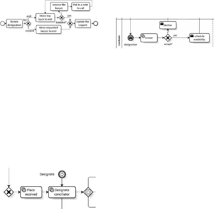
Figure 5: Madiba BPMN AS-IS, Request phase fragment.
After reviewing the kind of designation, if it was
by shift, the top lawyer on the list must be moved to
the end, next, validate if he is enabled and update the
request with him. By the contrary, the lawyer must
be removed from the official list, take note to call him
after, and repeat the cycle until get an enabled lawyer.
If the conciliator was selected by the petitioner, af-
ter removed from the request is updated. The whole
business process was elaborated jointly with the client
using the whiteboard with markers on it. This guar-
anteed representing the business in the way and the
terms the client do and use.
Business Process TO-BE. Once approved the AS-
IS Process model the development team transformed
it into a TO-BE Process incorporating the software
to be build. As a result, the request phase frag-
ment, showed up, is transformed to a simple soft-
ware supported task: designate conciliator in Figure
6 that shows an excerpt of the TO-BE process for the
Madiba project.
Figure 6: Madiba BPMN TO-BE, Request phase cut.
Again, this activity was realized jointly with the
client (the lawyer group), and as a result, before elicit
requirements, it was possible to take decisions that
involve organizational, technical, financial and time
issues. As an example, the next activity after des-
ignate conciliator is to announce that to the lawyer.
In this example, the client decided to use the major
available technologies (i.e. SMS, e-mail and what-
sapp messages) to realize this ad in the way showed
in Figure 7
The conciliator receives a message asking her/him
be a conciliator for a case (i.e., the designation mes-
sage). He can accept by sending his availability (i.e.,
the schedule availability task), or can decline by send-
ing a justification (i.e., the decline task). The resulting
requirements specifications were faithful to the need
and decisions made by the client, and they are easily
verifiable in the TO-BE process.
Figure 7: Madiba BPMN TO-BE, Request phase cut.
4 CONCLUSIONS
We found that BPMN help us to elicit the require-
ments, because the stakeholders were able to discuss
and propose changes to the artifacts, to the scope and
the requirements of the software.
Our current and future work is focused on (1) im-
plementation of traceability between the high level ar-
tifacts depicted here towards the code, to facilitate the
software evolution and requirements change manage-
ment. (2) Research on ways to manage BPMN ar-
tifacts (linked with use cases and code) as software
assets with which a software product line strategy can
be implemented.
REFERENCES
Jacobson, I., Booch, G., and Rumbaugh, J. (1999). The Uni-
fied Software Development Process. Addison-Wesley.
Monsalve, C., April, A., and Abran, A. (2012). On the ex-
pressiveness of Business Process Modeling notations
for Software Requirements elicitation. In 38th An-
nual Conference on IEEE Industrial Electronics So-
ciety (IECON 2012). IEEE.
OMG (2011). Business process model and notation, version
2.0.
Przybylek, A. (2014). A Business-oriented Approach to Re-
quirements elicitation. In 9th International Confer-
ence on Evaluation of Novel Approaches to Software
Engineering (ENASE). IEEE.
Sedelmaier, Y. and Landes, D. (2014). Using Business Pro-
cess Models to foster competencies in Requirements
Engineering. In 27th Conference on Software Engi-
neering Education and Training (CSEE&T). IEEE.
Software Development Process Supported by Business Process Modeling - An Experience Report
245
