
Automated Unit Testing in Model-based Embedded Software
Development
Christoph Luckeneder
1
, Hermann Kaindl
1
and Martin Korinek
2
1
Institute of Computer Technology, TU Wien, Vienna, Austria
2
Robert Bosch AG, G
¨
ollnergasse 15-17, Vienna, Austria
Keywords:
Automated Testing, Unit Tests, Model-based Development, Embedded Software, Safety-critical Systems,
Automotive.
Abstract:
Automating software tests is generally desirable, and especially for the software of safety-critical real-time
systems such as automotive control systems. For such systems, also conforming with the ISO 26262 standard
for functional safety of road vehicles is absolutely necessary. These are embedded systems, however, which
pose additional challenges with regard to test automation. In particular, the questions arise on which hardware
platform the tests should be performed and by use of which workflow and tools. This is especially relevant in
terms of cost, while still ensuring conformance with ISO 26262.
In this paper, we present a practical approach for automated unit testing in model-based embedded software
development for a safety-critical automotive application. Our approach includes both a workflow and sup-
porting tools for performing automated unit tests. In particular, we analyze an as-is workflow and propose
changes to the workflow for reducing costs and time needed for performing such tests. In addition, we present
an improved tool chain for supporting the test workflow. In effect, without manually implementing each test
case twice unit tests can be performed both in a simulation environment and on an open-loop test environment
including the embedded platform target hardware.
1 INTRODUCTION
Automotive systems have more and more become
software-intensive systems, which include large-scale
software systems. They are cyber-physical systems,
and they execute in a complex embedded platform
and environment. Since these are safety-critical sys-
tems, automated testing is particularly desirable in
this context. Due to the expected further growth of
the software involved, scalability of test automation
is an issue, also with regard to the costs and the time
needed for testing.
This paper shows how to automate unit tests of
such embedded software. This software has to be
flashed on the Engine Control Unit (ECU) of an auto-
mobile, and this fact poses a challenge for automated
testing. We present how the existing workflow within
sub-processes of the test process was altered and en-
hanced through tool support, with a focus on less time
and effort needed for unit testing. In this workflow,
tests are designed to run on the open-loop test setting
including the real ECU and, in addition to the previ-
ous practice, also on a simulator, both with the same
test suite.
The following support through a tool chain was
planned: modeling and simulation of the resulting
software models, as well as model-based test automa-
tion. Due to problems with the interplay of the given
proprietary tools, two additional tools had to be pro-
vided for real automation of the new workflow. One
tool creates the necessary settings in the configura-
tion file and coordinates the modification process for
flashing. Another tool provides a framework for the
setup of the test-case file and supports the tester dur-
ing configuration of the test-dependent settings in the
file to achieve platform independence.
This work is important for the practice of testing
in such an industrial environment, since it addresses
obstacles for introducing automated testing. Tests on
such a simulator have the advantages over tests on the
target hardware that flashing is not necessary and that
it is not necessary to wait for availability of this hard-
ware (both in cases of concurrent software/hardware
development and of scarce resources). However, ac-
cording to the safety standard ISO 26262 (Interna-
tional Organization for Standardization (ISO), 2011)
tests on a simulator alone are insufficient. So, for
Luckeneder, C., Kaindl, H. and Korinek, M.
Automated Unit Testing in Model-based Embedded Software Development.
DOI: 10.5220/0006469604270434
In Proceedings of the 12th International Conference on Software Technologies (ICSOFT 2017), pages 427-434
ISBN: 978-989-758-262-2
Copyright © 2017 by SCITEPRESS – Science and Technology Publications, Lda. All rights reserved
427

achieving efficient test automation, both tests had to
be integrated in the new workflow, and with the same
test suite for both.
The remainder of this paper is organized in the
following manner. First, we review related work and
present some background material in order to make
this paper self-contained. Then we explain both the
as-is and the proposed test workflows. Based on that,
we elaborate on the tool chain, including two newly
developed tools. Finally, we evaluate our approach
and conclude.
2 RELATED WORK
There is wide agreement that complete automation re-
duces testing cost, especially when regression test-
ing is involved. For example, 64% of the respon-
dents agreed to that in a literature review and prac-
titioner survey (Rafi et al., 2012). In particular, there
is some empirical evidence from a case study report in
the context of agile development (Collins and de Lu-
cena, 2012). Also within the automotive industry,
test automation is reported to be widely applied, see,
e.g., the results from a questionnaire survey (Altinger
et al., 2014).
Unfortunately, supporting tools on the market of-
fer a poor fit for the needs of automated testing ac-
cording to (Rafi et al., 2012), where 45% of the re-
spondents agreed to that. Note, that this survey was
on automated testing of software in general, but did
not cover testing of embedded software.
There exist several books like (Broekman and
Notenboom, 2003)(Gr
¨
unfelder, 2013), which specif-
ically deal with testing of embedded systems. Due to
the wide variety of embedded systems, they focus on
test techniques in general. They often present chal-
lenges in applying these techniques but cannot show
general solutions, because tools and test environments
often have to be tailored specifically for the embedded
system to be tested.
Conrad (Conrad, 2009; Conrad, 2012) deals with
verification and validation in the context of the IEC
61508 or ISO 26262, respectively. This work pro-
poses workflows using the same test cases on both
the simulation model (which is also used to generate
the implementation code) and the object code (possi-
bly running on the real hardware). We build on these
workflows and adapt them to the needs of the given
test environment. In addition, we describe obstacles
when putting this workflow into practice and provide
tool support to resolve them.
In the long run, the test cases should be gener-
ated automatically. However, test case generation is
not widely used yet in the automotive industry ac-
cording to (Altinger et al., 2014). Still, we found
a proposal for a technique in (Kamma and Maruthi,
2014). It deals with the requirement from safety stan-
dards such as ISO 26262 on unit testing to check all
functional requirements and achieve 100% coverage
of auto-generated code.
3 BACKGROUND
In order to make this paper self-contained, let us
present some essential background information. First,
we sketch how both code generation and simulation
are possible with a given commercial tool. Then we
explain the overall test environment.
3.1 Code Generation and Simulation
The embedded software development is supported
by the tool ASCET (Advanced Simulation and Con-
trol Engineering Tool) (ETAS, 2016). This tool is
dedicated to model-based development of automotive
software. It can directly generate C code for the em-
bedded platform hardware from a given model. Al-
ternatively, it can simulate the model on the host plat-
form. Actually, ASCET generates C code for such a
simulation. It is important to note that this C code
is different from the C code for the embedded plat-
form, e.g., because of stubbing. Figure 1 illustrates
both paths in terms of data flows. It also shows that
inputs in addition to the ASCET model are involved
as explained below.
3.2 Test Environment including the
Embedded Platform Hardware
Figure 2 illustrates the structure of the open-loop test
environment including the given embedded platform
hardware, and the data flows involved. This test en-
vironment includes a PC for control, an ECU as the
embedded platform, and a few other hardware com-
ponents.
TPT (Time Partition Testing) (PikeTec, 2016) is a
tool for testing embedded systems. It supports several
tasks in the course of testing, such as model-based
test-case generation as well as administration, exe-
cution, evaluation and documentation of tests. TPT
controls the tools INCA and LABCAR Software. All
these tools run on the PC for control of the open-loop
test environment.
INCA (Integrated Calibration and Acquisition
System) (ETAS3, 2016) is a software tool for the
ICSOFT 2017 - 12th International Conference on Software Technologies
428

ASCET Model
Code Generator
(Simulation)
Code Generator
(Hardware)
C Code
(Simulation)
C Code (Hardware)
Host Compiler Target Compiler
HEX- und A2L-Files
DLL for the Simulation
Previous Release of
Software
Necessary
Extentions for the
Simulation
Automotive
Library
Figure 1: ASCET Code Generation for Simulation and Embedded Platform Hardware.
INCA
LABCAR
Software
TPT
ESxxx
LABCAR
Signal Box
Breakout
Box
ECU
Throttle
Valve
Load
Simulator
PC for Control
Figure 2: Open-loop Test Environment.
support of tests on the embedded hardware. It com-
municates with the hardware control device ESxxx,
which serves as an adapter between the software and
interfaces such as CAN and ETK. LABCAR Soft-
ware (ETAS4, 2016) communicates with the LAB-
CAR Signal Box hardware for setting digital and ana-
logue signals on the pins of the ECU.
For running unit tests under regular conditions on
the ECU, this test environment additionally includes a
(real) Throttle Valve and a Load Simulator. They are
connected with the other components with a Breakout
Box.
4 WORKFLOWS FOR UNIT
TESTING
Based on this background information, we can ex-
plain the test workflows for unit tests, both the as-is
and the adapted workflow.
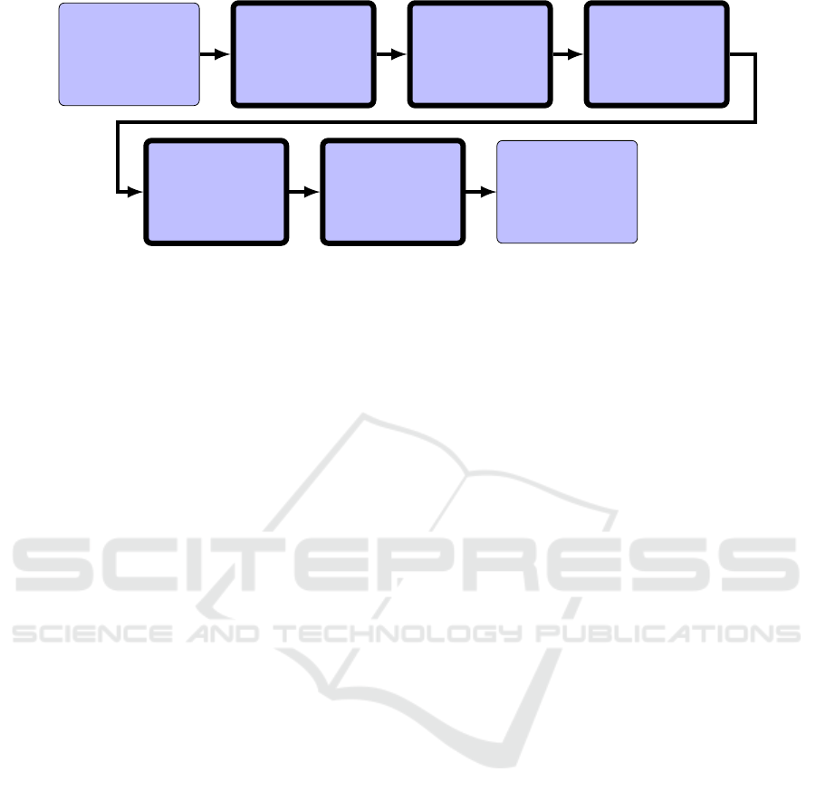
4.1 As-is Workflow for Unit Testing
Figure 3 shows the as-is workflow for unit tests. It is
a sequence of the following tasks:
1. Agreement on Test Environment
In principle, the test personnel may chose the test
environment for unit tests. However, for safety-
critical functions (ASIL B and up) tests have to be
performed in the test environment including the
embedded platform with the target hardware. For
this reason, nearly all of the tests have been per-
formed using the target hardware.
In addition, software used as test harness for the
unit tests has to be agreed upon. Unfortunately,
the usual approach to provide input for the unit
under test is insufficient in such an embedded sys-
tem, since the unit together with a minimal test
harness would not be executable. Alternatively,
a big-bang approach to use a system with all the
other units, yet still untested, would be possible,
Automated Unit Testing in Model-based Embedded Software Development
429

Agreement on Test
Environment
Static Analysis
Test-case Creation
Test Preparation
and Execution
Test Evaluation and
Documentation
Figure 3: Workflow for Unit Testing.
Software Build
(Generate HEX-
and A2L-Files)
Modify HEX- and
A2L-Files
according to Test
Cases
Flash Modified
HEX-Files
Test Execution on
the ECU
Figure 4: Subtasks of Test Preparation and Execution Task for Tests on the Embedded Platform Hardware.
but it would cause a lot of effort to handle all the
bugs outside of the unit under test. So, a previous
release of the whole software system is used as a
test harness for unit tests.
2. Static Analysis
Before these tests, the C code of a unit is checked
for compliance with conventions and for occur-
rences of specific types of errors.
3. Test-case Creation
Detailed test cases are defined for manual tests or
TPT-Files for automated tests. In addition to the
usual definition of defining inputs and expected
outputs for the unit under test, the test person-
nel has to determine how to inject signal values in
the previous release of the whole software, so that
the desired input for the unit results. Reasons for
this complication are given by the hardware and
certain plausibility tests in the overall software,
which in many cases make it insufficient to sim-
ply inject some input value for a signal directly for
the given unit. So, the test case implementations
actually contain the values of signals (such as the
engine speed) at a defined time and how they have
to be injected (e.g., through the LABCAR), pos-
sibly different from the direct input signal of the
unit under test.
4. Test Preparation and Execution
Extensive preparations may have to be made for
tests using the target hardware, before the ac-
tual test execution. They are laborious, as shown
in Figure 4 through the sequence of subtasks
involved. After the compilation of the source
code, which results in HEX- and A2L-Files, these
have to be modified for adaptations needed in the
course of integrating the unit to be tested into the
previous release of the software system. Techni-
cally, the program eHooks (ETAS2, 2016) intro-
duces so-called bypasses according to a configu-
ration file prepared by the test personnel, which
defines the related signals involved. Before the
actual test execution using the target hardware,
the modified HEX-file has to be flashed. This
is primarily done manually and involves several
project-specific parameters.
5. Test Evaluation and Documentation
Finally, the tests have to be evaluated and docu-
mented, including the test results, of course.
For appreciating the effort and time involved in
performing tests on the embedded platform hardware,
it is necessary to have a closer look into the required
activities. Since unit tests have to be performed within
a previous release of the software system, the function
to be tested has to be integrated into it. This involves
the effort for manual specification of the bypasses as
well as time for running the related scripts for build-
ing this integrated software. The latter typically re-
quires 30 minutes up to some two hours, depending
on the size of this software and the given hardware
configuration.
All this entails that unit testing using the target
hardware involves large overhead both in terms of ef-
fort and elapsed time. Apart from the effort and time
required for fixing a bug found in the course of such a
test, a new test run using the target hardware involves
this overhead again. In addition to the accumulating
effort and time per se, this makes unit testing difficult
to plan and may lead to trouble in keeping deadlines.
4.2 Proposed Workflow for Unit Testing
Due to these disadvantages of testing by use of the
target hardware, we propose making use of the sim-
ulation option (of ASCET) for unit testing. The for-
mer cannot be avoided completely because of the re-
quirements deriving from ISO 26262, but the latter
may help finding many bugs faster and with less effort
already before. We propose, therefore, an extended
workflow for unit testing as given in Figure 5.
ICSOFT 2017 - 12th International Conference on Software Technologies
430
Agreement on Test
Environment
Static Analysis
Test-case Creation
Test Execution on
Simulator
Test Evaluation of
Test on Simulator
Target Hardware
Test Preparation
and Execution
Test Evaluation and
Documentation
Figure 5: Proposed Workflow for Unit Testing.
Unfortunately, the test harness used on the target
hardware cannot be used for the simulator, since this
simulator cannot handle the complexity of a whole
software release. However, TPT can generate a test
harness specific for the unit under test from its AS-
CET model. In effect, two different test harnesses
have to be used in the proposed workflow.
This proposed workflow involves an extension of
the Static Analysis task of the as-is workflow. If er-
rors in the interface definition of the unit under test
were undetected until the later task of preparing the
tests using the target hardware, effort with test case
creation and related simulations may be wasted. So,
we propose checking the interface definition against
the (previous release of the) whole software system
already at this stage.
In the course of Test-case Creation, TPT is used
for test case implementation so that they can be au-
tomatically executed. Because of the two different
test harnesses, the same test case must actually be im-
plemented twice, but we need to make sure that the
unit under test receives the same input in both situ-
ations. So, a TPT-File with Port Specifications for
Tests on the Simulator and the open-loop Test Envi-
ronment has to be provided as explained below.
When using the test cases from the as-is work-
flow as explained above, it is necessary to specify
the corresponding inputs for the test execution with
the simulator. If they are not yet available, they can
be easily determined in the course of a test execution
on the target hardware. The other way round, when
new test cases will be available, ideally generated au-
tomatically through some tool, they will most likely
be formulated with the inputs directly for the unit un-
der test, which is to be used on the simulator. In this
case, however, it is necessary to determine the inputs
(and how it is to be injected) for the whole system as
a test harness on the target hardware. This is less triv-
ial, and in order to free the tester from this task for
every test case specified, we automated it by imple-
menting a specific tool for storing and retrieving this
input information (as explained below).
Based on the test case implementation for the sim-
ulator, TPT controls the simulation of the model in
ASCET. Note, that this can be done with little over-
head on the host PC. In addition, these tests on the
simulator do not have to run in real-time and can,
therefore, usually run faster than using the target hard-
ware. Both contributes to more efficient testing on the
simulator as compared to the target hardware.
Testing by use of the target hardware does not
make sense as long as bugs are found in the simu-
lation environment. Checking for that is the purpose
of the newly introduced task Test Evaluation of Test
on Simulator.
Target Hardware Test Preparation and Execution
is (still) according to the subtasks and their sequence
as given in Figure 4. So, the related overhead cannot
be completely avoided. However, the number of such
tests is supposed to be reduced significantly, due to
the prior tests in the simulation environment.
Test Evaluation and Documentation is still re-
quired, of course. TPT is used here now for automa-
tion of most activities involved, however.
5 TOOL SUPPORT
Both the as-is and the proposed workflow require tool
support in order to let them really facilitate test au-
tomation. Still, only using the commercial tools as
sketched above is insufficient for that purpose. First,
we explain the shortcomings of the given tool chain.
Based on this brief analysis, we propose two addi-
tional tools, both of which are already implemented.
5.1 Shortcomings of Tool Chain
These shortcomings of the tool chain are primarily
tools missing for seamless support of automated test-
Automated Unit Testing in Model-based Embedded Software Development
431
A2L-File
eHooks-Prep
HEX-File
Prep-Config
TPT-File
Modify-Tool Dev-Config
Prepared A2L-File
eHooks-Dev
Modified A2L-File
Modified HEX-File
Compiler Output
Specific to Project
Test-case Creation
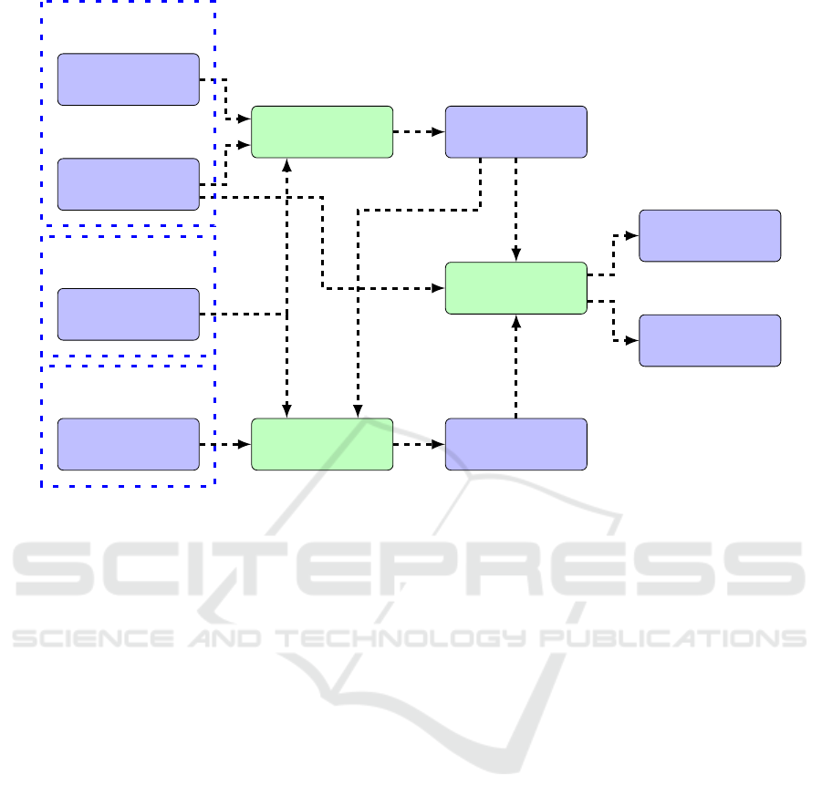
Figure 6: Data Flow between Software Tools (shown in green).
ing of our embedded software. One major loophole
in the given tool chain was lacking support for auto-
mated configuration of the modifications required for
integrating the function under test into the (previous
release of the) whole software system. Manual con-
figuration is error-prone and would have affected both
the as-is and the proposed workflow. The other prob-
lem was to make sure that the part of the test case im-
plementation specifying the input and expected out-
put signals characteristic can be reused for both sim-
ulation on the host and testing by use of the target
hardware. Lack of related tool support would have
affected the proposed workflow for testing, since it
involves both kinds of tests.
5.2 New Tools
For addressing the first of these problems, we devel-
oped a piece of software named Modify-Tool. It sup-
ports the subtask Modify HEX- and A2L-Files ac-
cording to Test Cases of Figure 4. The overall data
flow between this new tool and the two commercial
tools eHooks-Prep and eHooks-Dev (both from the
company ETAS) is illustrated in Figure 6. Based on
the TPT-File given as its input, Modify-Tool outputs
the configuration file Dev-Config, which is the basis
for these modifications. More precisely, it determines
for the given signal mapping, which of the signals
have to be assigned a bypass for the unit test. It also
checks whether the signals exist in the (previous re-
lease of the) whole software system. For manual unit
tests, the tool also provides a function that allows the
user to generate a Dev-Config file based on the name
of the function to be tested. In addition, Modify-Tool
supports the test personnel in coordinating the modi-
fications by calling the other tools involved.
For addressing the second problem, we developed
a piece of software named Setup-Tool. It supports the
test personnel in creating TPT-Files that cover both
cases. Figure 7 shows the related data flow. Based on
the TPT-Template with Port Specification for Tests on
Simulator of the unit under test and a Mapping-File
given as its input, Setup-Tool outputs a TPT-File with
Port Specifications for Tests on Simulator and Open-
loop Test Environment. The Mapping-File contains
one or more mappings, each of which is a specifica-
tion of how data for a signal directly input at the unit
under test has to be converted into signal data to be
injected into the whole system, and how this injection
is done. It performs the conversion of correspond-
ing signals automatically. So, the additional effort in-
volved for creating both test case implementations as
compared to the test case implementation for the sim-
ulator only, is small.
ICSOFT 2017 - 12th International Conference on Software Technologies
432
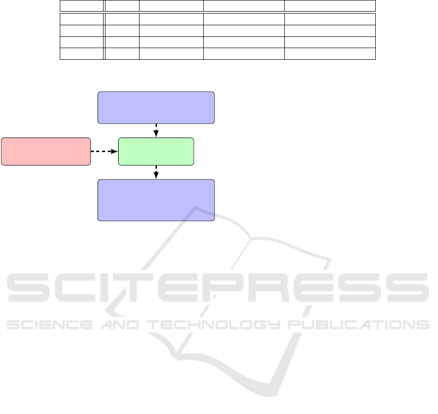
Table 1: Testable units in percent.
Gen Gen + Spec 1 Gen + Spec 1 & 2 Gen + Spec 1, 2 & 3
PVER 1 76.13 77.72 87.47 88.10
PVER 2 77.43 78.95 88.52 89.15
PVER 3 62.90 67.35 86.93 87.13
PVER 4 55.52 61.52 84.57 85.05
TPT-Template with Port
Specification for Tests on
Simulator
Setup-ToolMapping-File
TPT-File with Port
Specifications for Tests on
Simulator and Open-loop Test
Environment
Figure 7: Data flow of the Setup-Tool for Creating
Platform-independent TPT-Files.
5.3 Discussion
Of course, we could have produced two TPT-Files
(one for tests on the simulator and one for tests on the
open-loop test environment). We decided to do oth-
erwise because this would raise a problem regarding
consistency between those two files.
Our new tools are useful for bridging the existing
commercial tools. However, our tools are extremely
dependent on these other tools, in particular their file
structure. Since we have no influence on the further
development of those commercial tools, adaptions of
our tools may become necessary whenever a new ver-
sion comes up. This coupling seems to be inherent in
such a test environment, however, and the tool inter-
operability in this context remains an open issue.
The approach taken with our new Setup-Tool is
worth being briefly discussed with regard to ISO
26262. All tools directly used during the test execu-
tion need to be certified according to this safety stan-
dard. This is for a good reason, but takes its time and
is costly as well. In fact, a translator running in the
course of the automated test execution were directly
involved and would, therefore, have to be certified. In
contrast, our Setup-Tool is not directly used during
the test execution. It just prepares the test cases in a
platform-independent way before the automated test
execution, and this could be done manually as well.
So, such a tool does not have to be certified according
to ISO 26262.
6 EVALUATION
As explained above, our new workflow and especially
the desired reduction of the time needed for unit test-
ing are based on the assumption that a unit can be
tested on the hardware and the simulator with the
same test cases. In the course of an evaluation, ex-
isting unit models and corresponding unit test cases
of real Engine-Control-Unit-Software were used. Be-
cause these units and their implementations were al-
ready used in a test software which passed all qual-
ity gates necessary for official software release, no
errors were expected to be found with the given test
cases. This was actually the case and, unfortunately,
we did not have versions of the software available
that still had bugs to be found using these test cases.
Hence, this evaluation could not, unfortunately, show
whether the simulation is actually able to find errors
more cheaply than a hardware test or not. Still, we in-
directly verified the stubs (provided by the simulation
environment) related to units used for our evaluation,
since the simulation did not produce false errors. We
still consider this an important result of this evalua-
tion, because unnecessary revision of the model could
be very time consuming as well.
In addition, we studied another problem of the old
workflow in the course of this evaluation, which our
new workflow can address to a certain extent. We
found that a high percentage of units were tested on
the hardware by injecting the input signals in such
a way that the unit under test is directly stimulated.
However, this was not possible for all units when
embedded in a whole PVER, because of plausibility
checks within the PVER. These plausibility checks
monitor certain variables regarding consistency. If
one or more of these variables are altered indepen-
dently from the others involved, consistency is not
guaranteed. In such a case, the whole system switches
to an emergency mode.
Our new workflow generally stimulates the unit
under test directly, as usual for a unit test. For
running such test cases on the hardware, where the
unit under test is embedded in a whole PVER, our
new Setup-Tool can be used for creating TPT-files
to given Mapping-Files. For evaluating this new ap-
Automated Unit Testing in Model-based Embedded Software Development
433

proach supported by our Setup-Tool within our new
workflow, we performed a static analysis to deter-
mine the percentage of units of a specific variant of a
real Engine-Control-Unit-Software (in short, PVER)
testable in this way. Table 1 shows these percentage
numbers for four different variants (PVER 1 to 4). In
more detail, we analyzed each unit in the PVER re-
garding its input signals. We considered a unit as
testable with our workflow including simulation, if
the Mapping-File used offers a solution for signal in-
jection. Each column represents a different Mapping-
File. In the first one, the desired values are injected
directly and with a generic mapping (Gen). The other
Mapping-Files contain one and up to three special
mappings (Spec), each for one signal. Based on this
analysis, we argue that a high percentage of units can
be tested with the new workflow. However, to reach a
value close to 100 percent, more mappings will have
to be defined.
7 CONCLUSION
The approach presented in this paper facilitates ef-
ficient automated unit testing of embedded software
both with the ASCET simulator and using the target
hardware. Through the usage of the test-automation
software TPT and of our two new tools in the ex-
tended workflow, a shorter and more predictable du-
ration of unit testing is expected. In essence, we pro-
pose an adapted workflow for automated testing with
tool support that uses the same test cases on a simu-
lator and the target hardware. Compared to the as-is
workflow, the proposed workflow with its tool support
even reduces the manual workload of the tester.
A prototypical implementation of both the new
workflow and its supporting tools shows the feasibil-
ity of this approach. Future work will include case
studies for getting quantitative data on the potential
savings.
ACKNOWLEDGMENT
Part of this research has been carried out in the Fea-
tureOpt project (No. 849928), funded by the Austrian
BMVIT (represented by the Austrian FFG).
REFERENCES
Altinger, H., Wotawa, F., and Schurius, M. (2014). Testing
Methods Used in the Automotive Industry: Results
from a Survey. In Proceedings of the 2014 Workshop
on Joining AcadeMiA and Industry Contributions to
Test Automation and Model-Based Testing, pages 1–
6, New York, NY, USA. ACM.
Broekman, B. and Notenboom, E. (2003). Testing embed-
ded software. Pearson Education.
Collins, E. and de Lucena, V. (2012). Software test au-
tomation practices in agile development environment:
An industry experience report. In Automation of Soft-
ware Test (AST), 2012 7th International Workshop on,
pages 57–63.
Conrad, M. (2009). Testing-based translation validation of
generated code in the context of IEC 61508. Formal
Methods in System Design, 35(3):389–401.
Conrad, M. (2012). Verification and validation according
to ISO 26262: A workflow to facilitate the develop-
ment of high-integrity software. Embedded Real Time
Software and Systems (ERTS2 2012).
ETAS (2016). ETAS GmbH, Stuttgart, Germany.
http://www.etas.com/en/products/ascet soft
ware
products.php.
ETAS2 (2016). ETAS GmbH, Stuttgart, Germany.
http://www.etas.com/en/products/ehooks.php.
ETAS3 (2016). ETAS GmbH, Stuttgart, Germany.
http://www.etas.com/en/products/inca.php.
ETAS4 (2016). ETAS GmbH, Stuttgart, Germany.
http://www.etas.com/en/products/labcar software pro
ducts.php.
Gr
¨
unfelder, S. (2013). Software-Test f
¨
ur Embedded Sys-
tems: Ein Praxishandbuch f
¨
ur Entwickler, Tester und
technische Projektleiter. dpunkt. verlag.
International Organization for Standardization (ISO)
(2011). ISO 26262 Road vehicles - Functional safety.
Kamma, D. and Maruthi, P. (2014). Effective Unit-testing
in Model-based Software Development. In Proceed-
ings of the 9th International Workshop on Automation
of Software Test, AST 2014, pages 36–42, New York,
NY, USA. ACM.
PikeTec (2016). PikeTec GmbH, Berlin, Germany.
http://www.piketec.com/en/2/tpt.html.
Rafi, D., Moses, K., Petersen, K., and Mantyla, M. (2012).
Benefits and limitations of automated software test-
ing: Systematic literature review and practitioner sur-
vey. In Automation of Software Test (AST), 2012 7th
International Workshop on, pages 36–42.
ICSOFT 2017 - 12th International Conference on Software Technologies
434
