
Design and Control of a Force Reflecting Arm Exoskeleton for
Virtual Reality Applications
Dimitar Chakarov, Ivanka Veneva, Mihail Tsveov and Dimitar Trifonov
Institute of Mechanics, BAS, Acad. G. Bonchev str. Block 4, Sofia, Bulgaria
Keywords: Exoskeleton Arm, Design, Haptic Device, Impedance Control, Pneumatic Muscle, Joint Torque, Antagonistic
Interaction, Virtual Gymnastics.
Abstract: In this paper, the design of an exoskeleton for the upper limb is presented, aimed primarily at training and
rehabilitation in virtual environments. A mechanical model of the exoskeleton arm as haptic device is built
up and impedance control scheme is selected as the most suitable for force reflection at the arm. The design
of a grounded exoskeleton prototype is revealed in the paper. A driving system based on braided pneumatic
muscle is selected to ensure natural security in the interaction. Antagonistic drive system for each joint is
shown, using pulley and Bowden cable transmissions. An approach is presented for the joint moments control
by antagonistic interaction of bundles with different numbers of pneumatic muscles. Control scheme of joint
torque by antagonistic interaction is given, too. Computer simulations are performed to provide power
reflection by virtual reality (VR), according to scenario of virtual gymnastics.
1 INTRODUCTION
Exoskeleton is outside wearable robot with joints and
limbs corresponding to those in the human body.
Active exoskeletons transmit their driving
mechanisms human joints moments. Exoskeletons
are used in four main functions in accordance with
their control algorithms (Perry, 2007): a)
Rehabilitation - related closely to the body, they
perform tasks of physical therapy in active or passive
operation; b) Haptic device - people physically
interact with virtual objects, as the forces of
interaction apply to humans through the exoskeletons
actuators; c) Master device - at control type "master-
slave", the forces of interaction apply to exoskeleton
- "master"by the robot-"slave"; d) Assisted human
device - amplifier of the human body, the operator
feels lighter loads, adopted by exoskeleton.
With the increase in recent years of applications,
related to interaction in virtual environments
increases the importance of the second function:
using exoskeleton as Haptic device. Haptic interfaces
allow humans to perceive and transmit forces and
movement of real and virtual entities and actually to
be "immersed" in virtual reality. It is possible to give
people the illusion, that they have another body in
immersion in virtual reality. When you move you see
the virtual body to move in the same way (Slater,
2014), through motion capture in real time. This
function for using exoskeletons is combined
effectively with their other application - as a device
for rehabilitation, using virtual scenarios.
In literature are presented many exoskeletons
possessing very different mechanical structure and
drive, with or without force feedback effect. The first
modern exoskeleton of human upper limb was
designed by PERCRO to feel and response in contact
and collision with real and virtual entities
(Bergamasco, 1994). The authors of PERCRO
developed researches with designing other
exoskeleton of human upper limb for Haptic
interaction with virtual environments L-Exos (Frisoli,
2009).
Exoskeleton is known with pneumatic actuators,
developed by (Lee, 1998). Their device is with 9
degrees of freedom and allows full playback of
human hand workspace of exoskeleton. Alternative
exoskeleton is developed by (Jeong, 2001), which is
designed to overcome the limited bearing capacity of
previous projects, using parallel mechanisms and
pneumatic drives. Other examples of exoskeletons,
targeted primarily for rehabilitation are ARMIN of
the University of Zurich (Nef, 2007) and LDCs at the
University of Salford, which uses pneumatic
actuators (Tsagarakis, 2003). Comfortable to wear
Chakarov, D., Veneva, I., Tsveov, M. and Trifonov, D.
Design and Control of a Force Reflecting Arm Exoskeleton for Virtual Reality Applications.
DOI: 10.5220/0006427403350342
In Proceedings of the 14th International Conference on Informatics in Control, Automation and Robotics (ICINCO 2017) - Volume 2, pages 335-342
ISBN: Not Available
Copyright © 2017 by SCITEPRESS – Science and Technology Publications, Lda. All rights reserved
335

hand of Salford overcomes some of the problems and
limitations of previous designs. This soft hand-
exoskeleton is used for physiotherapy and for
training.
These devices have to meet the safety
requirements except the traditional requirements for
performance. It is important to develop exoskeletons
possessing naturally low impedance in order to
achieve natural safety in the mutual interaction “man-
robot”.
One of the most common approaches to
implement natural compliance is the usage of
pneumatic artificial muscles (Daerden, 2002),
(Tsagarakis, 2003), (Caldwell, 2007). The pneumatic
muscles are actuators with a high power/weight ratio
and can be directly coupled to the joint, without a
heavy and a complex gearing mechanism. The force-
deflection characteristic of these muscles, being
strongly non-linear, they can be used to achieve
compliance adjustment by means of an antagonistic
setup. The drawbacks of the pneumatic muscles are:
slow response to the input control, the presence of
hysteresis, making precise position control difficult to
realize and bringing the necessity of pressurised air.
Although various solutions are developed in order
to be achieved simultaneous safety and performance
within the human connected devices, there are still
significant barriers that should be overcome (such as
structure, drive and sense) to be able to provide
natural, safe and comfortable physical interaction on
the one hand and performance on the other. The
objective of this work is to introduce the design of an
active arm exoskeleton, ensuring natural, safe and
comfortable physical interaction with human and to
display force-related sensory information from a
virtual environment to the user. The exoskeleton is
designed primarily for training and rehabilitation in
virtual environments.
2 MODELING AND CONTROL
OF EXOSKELETON ARM
The device, which can be seen to function as a
powered exoskeleton, is build-up of a branched serial
structure, kinematics similar to the structure of the
human body as it is shown in Figure 1.
The kinematics structure consists of four movable
bodies 1, 2, 3, 4 and four rotational joints (Figure 1).
The first two rotational joints J1, J2 are incident and
mutually orthogonal in order to emulate the
kinematics of a universal joint with the same centre
of rotation as the human shoulder. The third and the
fourth joints J3 , J4 are selected to be two rotational
joints incident and mutually orthogonal in order to
emulate the kinematics of a universal joint with the
same centre of rotation as the human elbow flexion
and human shoulder rotation. Moreover, the third
joint was assumed to be coincident with the elbow
joint as it is shown in Figure 1. The effective
movements of so selected four joints simulate the
movements of human arm in the shoulder and elbow.
The exoskeleton upper limb structure has h = 4
degrees of mobility. This structure is chosen in order
to construct an arm exoskeleton consisting of two
equal type actuated universal joints.
J1
J2
J3
J4
EE
2
1
3
4
0
Figure 1: Structure scheme of exoskeleton arm.
Mechanical model of the upper limb exoskeleton
is build up, according to the kinematics scheme
shown in Figure 1. Generalized parameters are
accepted to be the parameters of relative movements
in the joints of exoskeleton represented by the (h x 1)
vector q. End-effector (EE) of exoskeleton arm
moves in the ν - dimensional operation space.
Assuming that the operator hand is connected at a
point to the exoskeleton end effector, further we will
consider exoskeleton operation space as 3 -
dimensional. The coordinates of the exoskeleton end-
effector are presented by (3 x 1) vector X. The relation
between the generalized parameters q and the
coordinates of the end-effector X is set by the direct
kinematic problem. Regarding velocities, we
formulate that problem by means of equality:
qJX
(1)
Above J is the (3 x 4) matrix of Jacoby.
To make the operator feel the simulated
dynamics, impedance control is selected as the most
suitable for force refection between the user and the
virtual environment. The impedance model in
Cartesian space is given by the following equation of
simplified dynamics
FX
Z
(2)
Above
ICINCO 2017 - 14th International Conference on Informatics in Control, Automation and Robotics
336

T
]XX;X;X[X
0
(3)
is vector of end effector motion parameters, and
]K;B;M[Z
(4)
is the mechanical impedance of the system in
Cartesian space including the matrix of inertia,
damping and stiffness M, B, and K.
An open-loop impedance controller with model-
feedforward is selected (Carignan, 2000). This type
of force control is called open-loop because there is
no force feedback from the device to the controller to
regulate the force output of the exoskeleton end
effector as it is illustrated by the control block
diagram in Figure 2. The goal of the model
feedforward, is to cancel out the corresponding terms
in the dynamics of the device. In control block
diagram of Figure 2 the feedforward terms for the
device stiffness and gravity are included. This scheme
allows the use of so called strategy “patient-in-
charge” when the patient lead the robot with a low
impedance K
d
and resistive forces are generated for
deviations from the target in the virtual scene.
+
∆Q
Q
d
J
T
G
+
+
Q=J
T
F
-
+
Δ
X
d
-
Δ
X
Exoskeleton.
joint control
F
d
Human
f
e
K
Δ
q
X
c
d
K
J
1
e
K
Q
f
VR
scenario
Δ
X
3D Unity
Virtual Engine
Figure 2: Block scheme of open-loop impedance controller
with feedforward stiffness compensation.
According to this diagram, the controller takes the
difference between the desired position deflection
∆X
d
=X
d
−Xo, and the actual position defection of the
haptic interface, ∆X ≡ X – Xo. Since the positions on
this linearized block diagram are represented by
deviations from some nominal position Xo, the
Cartesian position of the virtual interface and the joint
position of the exoskeleton ∆q are related through the
Jacobian J. In this diagram, the exoskeleton natural
stiffness is represented by joint-space stiffness K
e
which is the relationship between the joint torque
inputs and the differential angular output. The
following relationships can be obtained from the
block diagram
QGQQQ
f
d
(5)
]QGQQ[JKX
f
de
1
(6)
Above
]XX[KJFJQ
d
c
d
T
d
T
d
(7)
represents desired force command in joint space.
Similarly, in joint space the forces that the human
exerts on the exoskeleton end effector are generated
as:
FJQ
T
(8)
Note, that Q represents a physical, not control input
to the device. The term Q
f
in (5) represents force
command in joint space as a result of model
feedforward compensation. It is calculated in
accordance with modelled exoskeleton stiffness in
joint space K
e
f
according to equation
XJKqKQ
f
e
f
e
f
1
(9)
The (h x 1) vector of (5):
T
G
h1
G,...,G
(10)
is the vector of gravity torques, generated at the
exoskeleton joints. Its components:
n
1i
j
i
T
oij
q
gmG
, j = 1 ,…, h (11)
are determined by the mass of links m
i
, i=1…n, the
gravity acceleration vector in the base frame
g
0
=[g
x
,g
y
,g
z
]
T
and the position vector of the i-th link
centre of mass in the base frame ρ
i
= [ρ
x
, ρ
y
, ρ
z
]
T
. After
substituting equation (7), (8) (9) and (10) into (6) and
setting ΔX
d
=0, without loss of generality yields:
FGJX]KKK[
Tcf
e
c
d
c
e
(12)
Above
1
JKJK
e
T
c
e
represents the natural
stiffness of the exoskeleton in Cartesian space and
1
JKJK
f
e
T
cf
e
represents the stiffness model of
the exoskeleton in Cartesian space. The influence of
the member
]KK[
cf
e
c
d
, that represents the active
exoskeleton stiffness decreases, if the natural stiffness
of the exoskeleton
c
e
K
is close to the desired level
c
d
c
e
KK
. The aim is to develop an exoskeletons
possessing naturally low impedance suitable for
interaction with virtual objects where the value of the
desired environment stiffness is low.
Design and Control of a Force Reflecting Arm Exoskeleton for Virtual Reality Applications
337
3 MECHANICAL DESIGN AND
ACTUATION SYSTEM OF
EXOSKELETON ARM
The mechanical structure of exoskeleton system
includes two arms, that are grounded, as each arm is
built up, according to structural diagram if Figure 1.
Each arm has four active degrees of freedom,
corresponding to the natural motion of the human arm
from the shoulder to the elbow. Structure in Figure 1
is chosen in order to develop a powered exoskeleton
arm, in which two equal type universal joints with 2
DoF are used and so, unlike other solutions, circular
guide and three axes joints are avoided.
Each universal joint placed in the shoulder and in
the elbow consists of a cross shaft and pair of
rotational joint oriented at 90 ° to each other. The
cross shaft is formed as an angle, in which the human
hand is situated, as the axes of rotation intersect at a
point, coinciding with the point of rotation of the
human natural joint.
The basic parts of the exoskeleton arm structure
are made of aluminium. The arm is constructed for
use by a typical adult. All arm units are designed that
allow quick and easy adjustment of length, so making
it easy to accommodate a range of users. Plastic shells
are placed over the units with bands for attachment to
human limb. This design suggests a comfortable, light
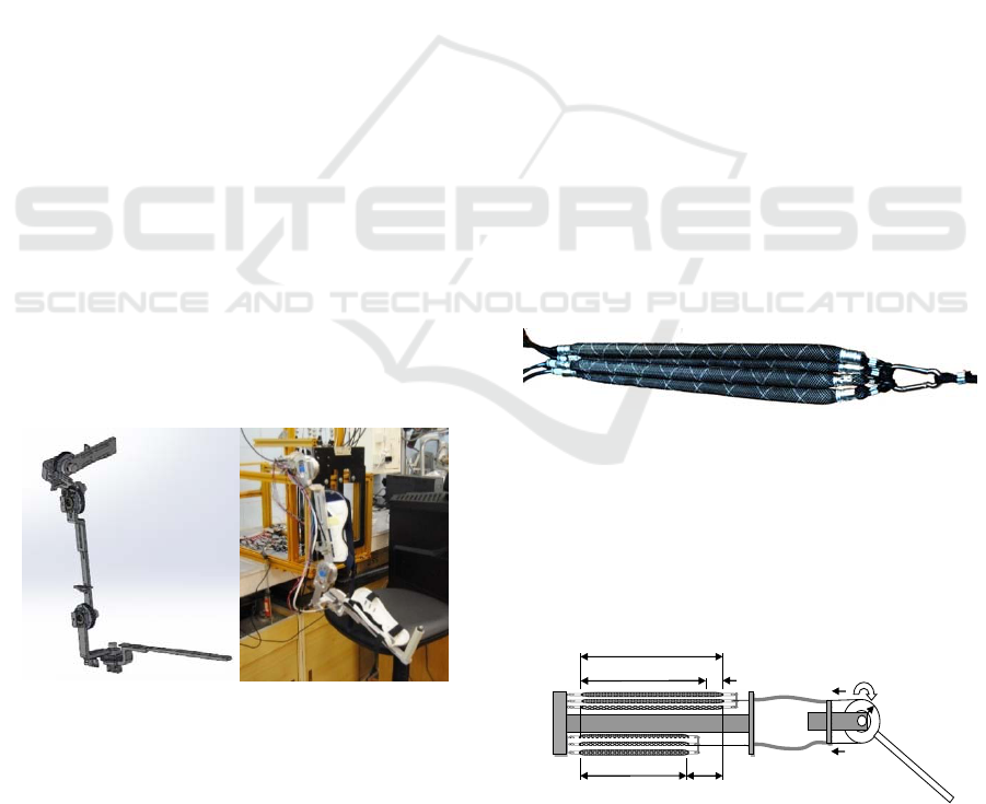
and low cost mechanical structure. In Figure 3, the
structure of the right arm exoskeleton is shown, as a)
is a computer simulation, and b) a picture of arm
prototype. Exoskeleton left hand is designed as a
mirror image of the right hand and is mounted on the
common fixed base.
a) b)
a) computer simulation, b) picture of arm prototype.
Figure 3: Structure of the right exoskeleton hand:
Masses of the exoskeleton arm units are defined using
CAD program. The masses of four basic units (Figure
1) are as follows m
1
=0.437 kg, m
2
=0.594 kg,
m
3
=0.364kg, m
4
=0.434kg. Lengths of exoskeleton
arm and forearm in the initial setup are as follows
0.286 m and 0.370 m respectively. The exoskeleton is
designed so, that it covers the requirements of
“Activities of daily living” (ADLs) as they have been
assessed in (Perry 2007). The ADLs range of motions
(ROM) and exoskeleton joint ranges of motions are
shown in Table 1.
Actuation system of exoskeleton arm should have
the following advantages: excellent power/weight
ratio with inherent safety, natural compliance, low
cost. To achieve these advantages self-made braided
pneumatic muscle actuators (PMA) are used. PMA
consists of two layers: an inner one, representing
rubber liner and outer one, representing braided
nylon. Endcaps are allocated at both ends, to which
are clamped by clips the two layers. In one endcap is
located a pipeline for supplying the pressurized air.
Muscles possess a maximum diameter D
0
= 0.016 m
and nominal length L
n
=0.390 m. Thus created PMA
are used not only singly, also in a sheaf of several
pneumatic muscle, as shown in Figure 4.
Muscles from the bundle are fed in parallel with
air at a maximum pressure 600 kPa (6 bar). Supply
pipeline is connected with two parallel arranged
valves of the type on / off, one of which serves to
supply the maximum pressure and the other for
discharge to the atmosphere. Pressure sensors are
connected to the supply pipeline at every muscle
bundle. All the muscles of the bundle are connected
mechanically in one and at the other end, where they
attach themselves.
Figure 4: Sheaf pneumatic muscle actuators.
Joint motion/torque on the exoskeleton arm is
achieved by antagonistic actions through cables and
pulleys, driven by the pneumatic actuators. Two
sheafs PMA, a and b, work together in an antagonistic
scheme, simulating a biceps-triceps system to provide
the bidirectional motion/force, (Figure 5).
0
a
Ln
L
C
C
max
L
min
b
P
b
S
P
а
T
1
T
2
q
r
Figure 5: Antagonistic scheme for joint motion/torque.
ICINCO 2017 - 14th International Conference on Informatics in Control, Automation and Robotics
338
Cable transmissions T
1
and T
2
are used for the
coupling between the muscles and the pulley. The
pulleys are fastened on the arm segments following
joint shafts. All actuators are mounted on the exo-
shell on the operator’s back. High precision rotation
sensors S are mounted in the joints.
According to the indications in Figure 5, muscle
contraction is defined as:
C = L
n
– L (13)
Muscle contraction C is typically presented as a
percentage of the nominal muscle length L
n
determined by the outer braided layer c=100 C/L
n
.
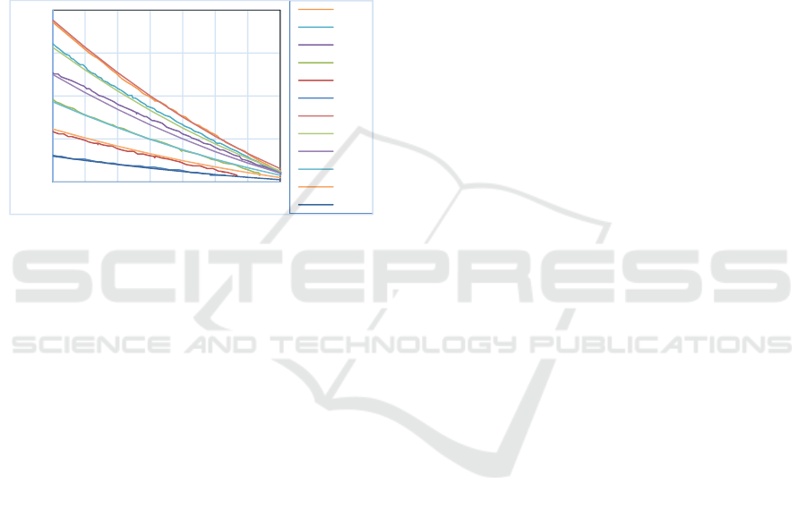
Figure 6: Graphs force / contraction of bundles of 1…6
muscles and their replicas at supply pressure of 400 kPa.
Experiments were conducted under static load of the
used PAM, as the number of muscle in a bundle and
the magnitude of the supply pressure has been altered.
At set pressure, the contraction of muscles is
measured by their nominal value L
n
to a minimum
value L
min
.
Experimentally obtained force/ contraction
diagrams (1m , … , 6m) for the used bundles
consisting of 1 to 6 muscles at constant supply
pressure of 400 kPa, are shown in Figure 6. At zero
pressure the muscles show elastic properties
determined of inner rubber liner. Pneumatic muscle
behaves like a pressure dependent variable
compliance spring. Graphs force/contraction of
braided pneumatic muscle actuators typically
represent quadratic functions. For replication of the
used PAM as a nonlinear quadratic spring (Caldwell,
2007) can be used the following equation
)LL(LKP
minp
. (14)
where: P is the pooling force of the muscles, L and
L
min
are the muscle lengths according Figure 5, K
p
is
a pressure dependent coefficient. Taking into account
(13) and equality for maximum contraction of muscle
bundle C
max
= L
n
– L
min
, equation (14) can be
transformed
)CC)(CL)(tpk(P
maxno
(15)
where: p is the operating pressure, k
o
and t are empiric
derived coefficients that depend on the muscle
number.
Approximated characteristics are composed for
bundles from different number muscles m = 1,2,3,4,5
and 6 at a pressure p = 100, 200, 300 and 400 kPa.
The maximum contraction of each muscle bundle is
c
max
= 40% Ln or C
max
=0.156 m. In the process of
approximation have been determined the following
relations of the coefficients k
o
and t in accordance
with the number of bundle muscles m: k
0
= -39 + 321
m, t = -0.21+ 4.41 m.
Approximated characteristics of muscle bundles
with 1, 2, ..., 6 muscles at a supply pressure of 400
kPa, are shown on Figure 6, (1m-a , … , 6m-a), where
they are compared with experimentally obtained
characteristics.
When the muscle bundles move the joint in an
antagonistic scheme (Figure 5), the current
contractions of each bundle in the joint C
a
, C
b
are
determined by the joint end positions q
max
, q
min
.
To generate the maximum forces, muscles are
attached so, as to operate with a minimum
contraction, i.e., in the end joint position, one bundle
has zero contraction and the contraction of the other
is determined according to the equation
*
q
rqC
(16)
where r is pulley radius and q* = (q
max
- q
min
) is joint
range of motion. Contraction (16) can be estimated as
effective contraction of both muscles and to be
presented as a percentage of the nominal muscle
length L
n
:
n
*
q
L/rq100c
. In each position of the
joint, the equation (16) represents the sum of the
preliminary contraction of the two muscle bundles.
In a current position q of the joint, the
contractions of the two muscle bundles are
)qq(rC
max
a
(17)
)qq(rCCC
min
aqb
(18)
The forces P
a
, P
b
of joint muscle bundles can be
calculated according to (15), (17) and (18). It is
assumed, that one muscle sheaf is active in one
direction, when the other is passive and vice versa at
the sign change of the torque, establishing a
maximum torque in the joint of antagonists muscle
actuators. The muscle bundles with zero pressure
always participate with a force in the joint
antagonistic equilibrium, as they are elastic.
Antagonistic balance in each joint is achieved by
0
200
400
600
800
0 5 10 15 20 25 30 35
P[N]
c%
6m
5m
4m
3m
2m
1m
6m‐a
5m‐a
4m‐a
3m‐a
2m‐a
1m‐a
Design and Control of a Force Reflecting Arm Exoskeleton for Virtual Reality Applications
339
generating desired torques in each joint, according to
equality:
)rP(PQ
abi
(19)
Since the bundle muscles with zero pressure (for
example a) p
a
= 0 generates elastic force P
a
according
to (15) end (17), draws (19), (15) and (18) allow to
calculate the required pressure p
b
of other muscles
(for example b)
)q,Q(fp
ib
(20)
According to control block diagram on Figure 2, the
joints torques Q
i
are set from equality (5) as
components of the vector representing force
command in joint space
T
4i1
Q,..,Q,...,QΔQ
(21)
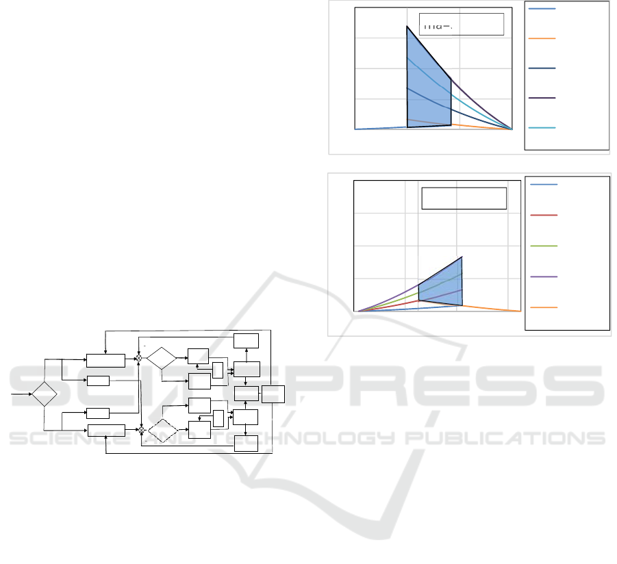
The control scheme of the joint torque caused by the
antagonistic interaction is shown in Figure 7.
Pressures in the muscle bundles p
a
and p
b
are
monitored by pressure sensors mounted to each
muscle sheaf.
PAM“a”
PAM“b”
Air
p
0
Presure
senso
r
“a”
Joint
Presure
sensor“b”
Position
sensor
p
b
Vending
Valve
Filling
Valve
Filling
Valve
Vending
Valve
Air
p
0
q
Q
i
p=0
-
+
p=0
p - p
a
-
+
-
+
p-p
b
∆Q
p
a
Figure 7: Control scheme of the joint torques.
A selection of bundles with different number of
muscles in every joint is performed to ensure nominal
torques in the joints and to provide joint moves q *
(Chakarov, 2014). Selected bundles antagonists with
number muscles m of the four arm joints are shown
in Table 1. The table shows also achieved torques for
each joint and muscles effective contractions.
For example, in Figure 8 is illustrated the change
of the moment in the shoulder joint, under the
influence of muscles antagonists a and b according to
contraction in abduction/adduction: a) in abduction is
active bundle b, which changes the pressure; b) in
adduction is active bundle a and its pressure is
changed. Shaded area of the chart shows the muscles
work area, corresponding to the stroke of the joint. In
this area, the achieved joint torque in according to
(19) depends on contraction and is amended for
shoulder abduction within the boundaries of 38.5 –
19.2 Nm, and for shoulder adduction within the
boundaries of 4.7 - 13.9 Nm. Similarly, graphics are
derived, amending moments in other joints. Table 1
shows the achieved torques for each joint.
a)
b)
Figure 8: Amendment of the torque in the shoulder joint
under the influence of muscle bundles antagonists a and b:
a) in abduction; b) in adduction.
4 COMPUTER EXPERIMENTS
FOR ENSURING FORCE
REFLECTION FROM VR
The exoskeleton is designed as a haptics device for
applications in virtual reality. For example, one
application is a virtual gymnastics. 3D Unity Virtual
Engine is used for data transfer between exoskeleton
and virtual entity (avatar) in virtual gymnasium.
Optical tracker HMD Oculus Rift is used for
visualization in the virtual system and to track the
head position and orientation. Exoskeleton is
designed to track position and orientation of human
body and to provide force feedback to human arm.
Figure 9 shows a scenario of virtual gymnastics - an
exercise with fitness cable machine.
When the user set optical tracker attached to his
head and "puts on the exoskeleton" as attaches the
upper limbs to both arms of exoskeleton, he is
"immersed" in the virtual scene gymnastics. Man gets
the ability to transmit movement to the avatar and
takes strength from it. One sees the virtual body to
move like him, through motion capture in real time.
0
10
20
30
40
‐20 0 20 40
Q[Nm]
C%
ma=3,mb=7
pa‐0
pb‐0
pb‐
200[kPa]
pb‐
600[kPa]
pb‐
400[kPa]"
0
10
20
30
40
‐25 ‐5 15 35
Q[Nm]
C%
ma=3,mb=7
pa‐0
pa‐
200[kPa]
pa‐
400[kPa]
pa‐
600[Kpa]
pb‐0
ICINCO 2017 - 14th International Conference on Informatics in Control, Automation and Robotics
340
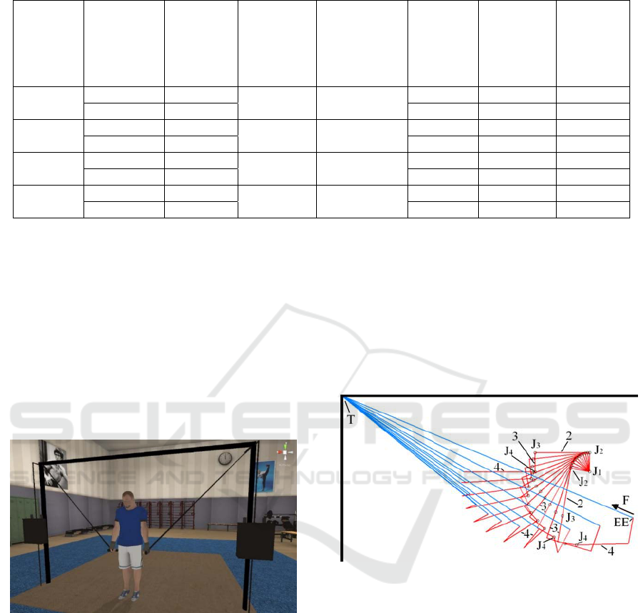
Table 1: ADLs and exoskeleton range of motions, effective muscle contractions, number of muscles and achieved torques.
Bundles
antago
nists
ADLs range
of
motions
[deg]
Exoskeleton
range of
motions
[deg]
Effective
muscle
contrac
tions
c%
Number of
the
muscles
in the
bundle
Achieved
torques
[Nm]
Shoulder
J1
Abduction b 100
110 15.5 7 38.5 – 19.2
Adduction a 15.5 3 4.7 - 13.9
Shoulder
J2
Flexion b 110
120 16.9 6 32.9 – 16.2
Extension a 16.9 3 5.2 - 14.8
Elbow
J3
Flexion b 150 150 21.1 4 21.9 – 7.8
Extension a 21.1 2 2.0 – 9.8
Elbow
J4
Int. rotation b 135 135 19.0 4 21.7 – 7.2
Lat. rotation a 19.0 3 4.3 – 15.8
The controller in Figure 2 creates power
commands in the joints of exoskeleton, that form the
force action on the user's hands, equivalent to the
power impact simulated in the virtual scene. In the
scene of virtual gymnastics with cable machine,
power influence is the tensile strength, which cable
exerts on hand. The magnitude of this force is a
constant, determined by the weight of the virtual
weight stacks. For this scene, virtual machine
generates a desired force command F
d
in the
controller in Figure 2, without taking into account the
desired Cartesian stiffness K
d
.
Figure 9: Scene of virtual gymnastics - an exercise with
cable machine.
Simulations were conducted for assessing the
projected exoskeleton ability to provide forceful
impact on the operator, as the described scene of
virtual gymnastics. Cable machine and the man’s
hand are simulated, as shown in the way in Figure 10.
The figure shows the right arm in several positions,
and the cable attached to the EE and slung over a roll
in a fixed point T. Experiments were carried out in the
following manner. A tensile force F is set, which
virtual cable exerts on the avatar hand. This is the
force, that exoskeleton must exercise over the hand of
man. Exoskeleton arm performs a movement of
maximum tension within the boundaries of joint
ranges. Torques in the exoskeleton joints (5) were
calculated by taking into account the desired moment
d
T
d
FJQ
, as well as joint component of gravity
compensation G. The desired force is assumed to be
equal to the cable force with reverse sign F
d
= -F.
Gravitational component (10) were calculated after a
preliminary masses and geometry assessment of the
exoskeleton movable units.
Figure 10: Simulation of the scene of virtual gymnastics
with cable machine.
All joints are driven by antagonist bundles,
consisting of different number muscles, performing
effective muscle contractions, as shown in Table 1.
Supply pressure for the active muscles changes on the
range of 0 – 600 kPa, until the pressure of the passive
ones is 0. The experiment shows that for values of the
tensile force F = 0-50 N, desired torques in the joints
of the exoskeleton are achievable within the limits of
the attainable torques, shown in Table 1. In Figure 11
are shown the results of the shoulder joint at the
movement "tension" with a force F = 50 N. It is shown
the change of the joint components of the moments
ΔQ, Q
d
, G, as well as the achieved maximum moment
in the joint Q
max
, which is a result of the antagonist
interaction of the bundles of muscles with maximum
Design and Control of a Force Reflecting Arm Exoskeleton for Virtual Reality Applications
341
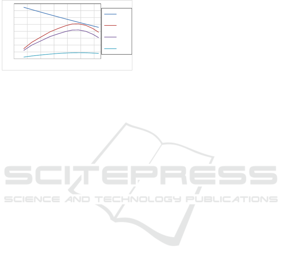
and minimum pressure. On the X axis is given the
contraction of active muscles bundle.
Figure 11: Amendment the joint components of ΔQ, Q
d
, G,
Q
max
, in the shoulder joint at cable force of 50 N.
5 CONCLUSIONS
In this paper, the design of an active arm exoskeleton,
aimed at human interaction with virtual environment
is presented. In the work, a mechanical model of the
exoskeleton arm, as haptic device is built up and
impedance control scheme is selected for force
refection at the arm. The design of a grounded
exoskeleton prototype with low mass/inertial
characteristics is revealed in the paper. To ensure
natural security in the interaction, a driving system
based on braided pneumatic muscle is selected.
Antagonistic drive system for each joint is shown,
using pulley and Bowden cable transmissions.
An approach for joint moments control by
antagonistic interaction of bundles with different
numbers of pneumatic muscles is presented.
Computer experiments have been carried out to
provide force reflection by VR, according to scenario
of virtual gymnastics. The conducted simulations
show the possibility of developed exoskeleton to
provide impact strength of 50 N on the hand of the
operator. Experiments with real exoskeleton
prototype were conducted with volunteers, where
they evaluate their feelings and their embodiment in
a virtual scene. Additional measurements and
evaluations of physical quantities are going to be
performed.
ACKNOWLEDGEMENTS
This work was funded by the European Commission
through FP7 Integrated Project VERE - No. FP7 -
257695 and by Bulgarian Science Found, Call: 2016,
through Project AWERON – DN 07/9, to which the
authors would like to express their deepest gratitude.
REFERENCES
Perry J., Rosen J, Burns S., 2007. Upper-limb powered
exoskeleton design. IEEE/ASME Transactions on
Mechatronics. Vol.12, No4, August 2007, pp. 408 –
417.
Slater M., Sanchez-Vives, M.V., 2014. Transcending the
Self in Immersive Virtual Reality. IEEE Computer 47
(7): 24-30 (2014), DOI: 10.1109/MC.2014.198.
Bergamasco M., B. Allotta, L. Bosio, L. Ferretti, G. Perrini,
G. M. Prisco, F. Salsedo, And G. Sartini, 1994. An Arm
Exoskeleton System for Teleoperation and Virtual
Environment Applications, IEEE Int’l Conf. Robot.
Automat., vol. 2, 1449–1454.
Frisoli A., Fabio Salsedo, Massimo Bergamasco, Bruno
Rossi And Maria C. Carboncini, 2009. A force-
feedback exoskeleton for upper-limb rehabilitation in
virtual reality, Applied Bionics and Biomechanics, Vol.
6, No. 2, June 2009, 115–126.
Lee,S., S. Park, M. Kim, And C.-W. Lee, 1998. Design of
a Force Reflecting Master Arm and Master Hand using
Pneumatic Actuators. IEEE Conference on Robotics
and Automation, May 1998, 2574–2579.
Jeong Y., Y. Lee, K. Kim, Y. Hong, And J. Park, 2001. A
7 DOF Wearable Robotic Arm using Pneumatic
Actuators,” in Proc. of the 32
nd
ISR International
Symposium on Robotics, April 2001, 388-393.
Nef T., M. Mihelji, and R. Riener, 2007. Armin: a robot for
patient-cooperative arm therapy. Medical & Biological
Engineering & Computing, 45 :887–900.
Tsagarakis N.G., Caldwell Dg., 2003. Development and
control of a “soft-actuated” exoskeleton for use in
physiotherapy and training. Autonomous Robots.
15(1):21–33.
Daerden Fr., D. Lefeber, 2002. Pneumatic Artificial
Muscles: actuators for robotics and automation.
European Journal of Mechanical and Environmental
Engineering, 47(1), 1 - 11.
Caldwell D.G. et al., 2007. “Soft” exoskeletons for upper
and lower body rehabilitation — design, control and
testing. International Journal of Humanoid Robotics
Vol. 4, No. 3, 549–573.
Carignan, C.R., K. R. Cleary, 2000. Closed- Loop Force
Control for Haptic Simulation of Virtual Environments,
Haptics-e, Vol. 1, No. 2, February 23, pp.1-14.
Chakarov, D., I. Veneva, M. Tsveov, T. Tiankov, D.
Trifonov, 2014. New Exoskeleton Arm Concept Design
and Actuation for Haptic Interaction with Virtual
Objects, Journal of Theoretical and Applied
Mechanics, Sofia, vol. 44, No 4, pp. 3-14, DOI:
10.2478/jtam-2014-00.
0
5
10
15
20
25
30
35
40
024681012
[Nm]
c%
Qmax
Q
Qd
G
ICINCO 2017 - 14th International Conference on Informatics in Control, Automation and Robotics
342
