Dynamic Simulation of Vertebral Column and Control of the Posture
using a Parallel Mechanism
Mouna Souissi
1
, Walid Amokrane
1
, Zefeng Wang
2
and Gerard Poisson
3
1
PRISME HEI-Campus centre, 2 Allee Jean Vaillee 36000 Ch
ˆ
ateauroux, France
2
FMM HEI-Lille, 13 Rue de Toul 59000 Lille, France
3
PRISME Laboratory, University of Orl
´
eans - INSA CVL, France
Keywords:
Simulation, Dynamic Brace, Human Spine, Vertebral Column, Mechanical Structure, Kinematics.
Abstract:
Adolescent Idiopathic Scoliosis (AIS) is a deformity of spine which occurs during growth. This paper presents
a novel method for simulation of a 2D and 3D trunk model and the adaptation of an existing parallel mechanism
to design parallel joints that can be used to correct abnormal postures of the human spine affected by scoliosis.
A 3D model of the system has been elaborated for simulation and design. Simulations results show that this
mechanism is able to permit some bending motions of human torso, taking into account the specifications of
forward, backward and left/right sideways bending amplitudes.
1 INTRODUCTION
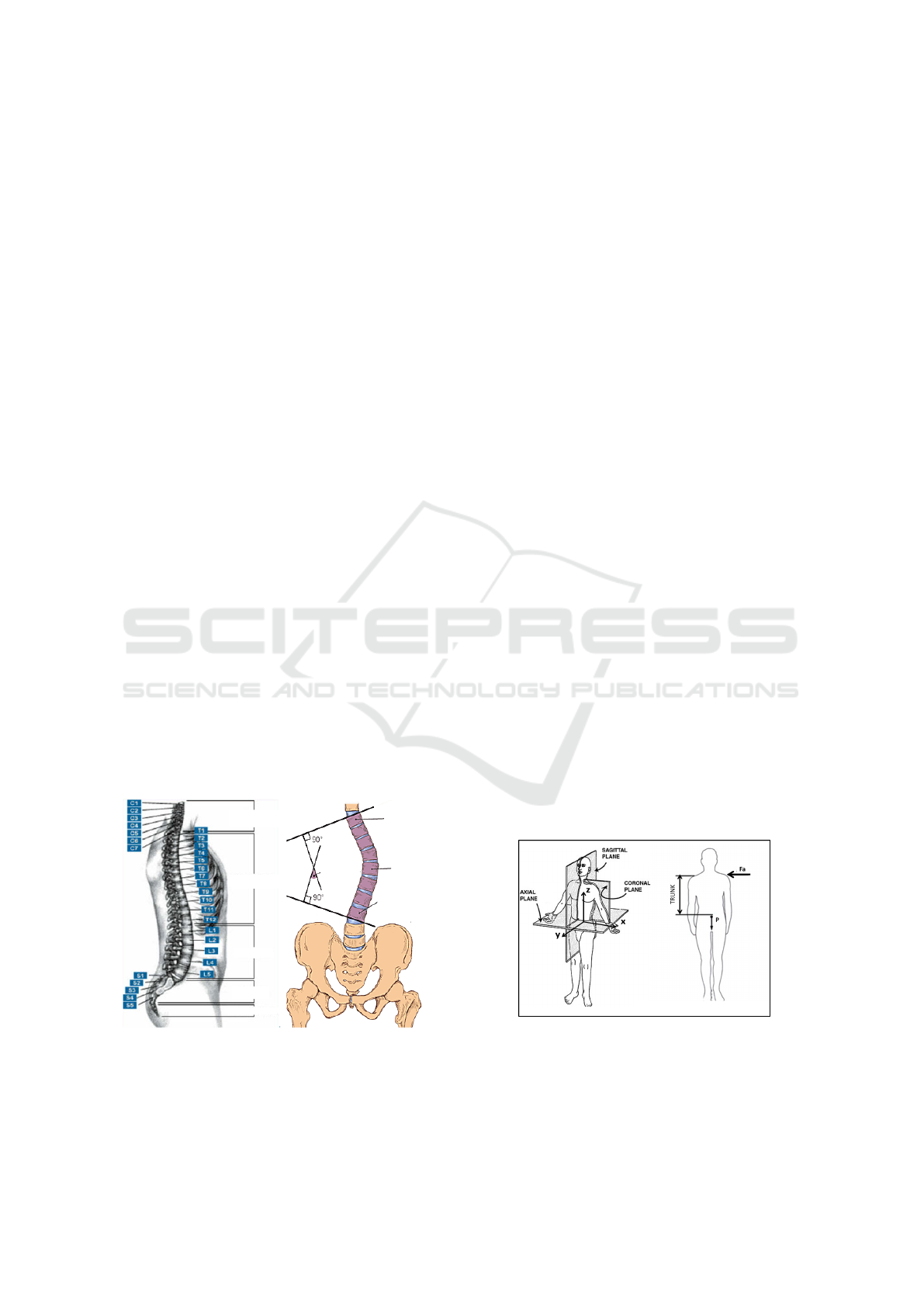
1.1 Human Spine Description
The human vertebral column extends from the skull
to the pelvis and is made up of 33 individual verte-
brae (Abbott et al., 2007). These later are stacked on
top of each other. They are grouped into four regions
(Fig. 1): cervical region, thoracic region, lumbar re-
gion, sacrum and coccyx.
(a)
(b)
Most titlted
vertebra
above apex
Apex
Most tilted
vertebra
below apex
Cobb angle
CERVICAL
THORACIC
LUMBAR
SACRUM
COCCYX
Figure 1: (a) Human Spine. (b) Cobb’s angle.
The cervical and lumbar regions enjoy the great-
est freedom of movement. In the thoracic region, mo-
tion is limited. Motions of a human spine are char-
acterized by the actuation planes that are the sagittal
plane, coronal plane, and axial plane (Fig. 2). The ba-
sic movements of the spine can be classified by using
planes, as follows:
• In Sagittal plane: Flexion and Extension
• In Coronal plane: Right and Left Lateralization
• In Longitudinal plane: Rotation
Deformity of spine is any abnormality of the for-
mation, alignment, or shape of the vertebral column.
Among the existing deformities, the deformation of
the spine is due to the scoliosis.
(a)
(b)
Figure 2: (a) Sagittal plane, coronal plane, and axial plane.
(b) Force applied to person to move in sagittal plane.
Souissi, M., Amokrane, W., Wang, Z. and Poisson, G.
Dynamic Simulation of Vertebral Column and Control of the Posture using a Parallel Mechanism.
DOI: 10.5220/0006397700170023
In Proceedings of the 14th International Conference on Informatics in Control, Automation and Robotics (ICINCO 2017) - Volume 2, pages 17-23
ISBN: Not Available
Copyright © 2017 by SCITEPRESS – Science and Technology Publications, Lda. All rights reserved
17
1.2 Spine of the Adolescent Idiopathic
Scoliosis (AIS)
A scoliosis curve usually looks a bit like a backward
C shape and involves the spine bending sideways to
the right, which is also called dextroscoliosis. Side-
ways spinal curvature on the left side of the back is
more like a regular C shape and called levoscoliosis.
Scoliosis is categorized into several types depending
on the cause and age of the curve development, 2%
to 3% of the population suffer from scoliosis (Ander-
son, 2007). There are four common types of scolio-
sis curves: right thoracic curve, right thoracolumbar
curve, right lumbar curve, double major curve. The
two parts affected by scoliosis are the thorax and lum-
bar regions.
To measure coronal plane deformity on antero
posterior plain radiographs in the classification of sco-
liosis Cobb angle is used. Cobb angle is defined as the
angles formed between a line drawn parallel to the su-
perior endplate of one vertebra above the fracture and
a line dawn parallel to the inferior endplate of the ver-
tebra one level below the fracture (Fig. 1).
A diagnosis of scoliosis is confirmed when the
Cobb angle, (J. Zhang, 2009) (Behairy, 2000) (Cobb,
1984) (Delorme, 2000), is 10 degrees or greater,
which is measured through a standard radiographic
examination. x-rays of the entire spine are taken to
evaluate the front and side curvature. The Cobb an-
gle is used on x-rays to measure the angle between
the most angulated vertebrae that make up the cur-
vature , (Longstein, 1994) (A. H. W. V. Eeuwijk,
2006) (Lafage, 2004). Lines are drawn on the x-rays
or a computer program assists to calculate the angle.
Most scoliosis curves are between 10 to 40 degrees in
magnitude. Although radiographic measurements are
used to decide treatment, a small degree of error ex-
ists when comparing radiographs. A change of 5 de-
grees is usually needed to document an actual change
in curve progression.
Treatment options for idiopathic scoliosis could
include: observation, bracing (Schiller and Eberson,
2010) (Aulisa and Aulisa, 2014) and surgery. Bracing
is the application of external corrective forces onto the
spine and trunk. It can be rigid or flexible. But con-
ventional rigid braces present some limitations: dif-
ficult to move, lower self-esteem, more fatigue and
lower compliance, heavy and non-breathable and un-
comfortable.
These braces are designed to be worn 16 to 23
hours a day. And as the child grows, the required ex-
ternal forces to correct the abnormal posture change
along the length of the curve and over the course of
treatment. Our objective is to achieve a dynamic bra-
ce. It is actuated by 2 motors placed on adjacent
rings to control the force or position applied on the
human body. In this paper we propose to investigate
the kinematics design of a vertebral column for hu-
man. Three kinds of experiments are carried out, first
experiment of spine in the sagittal plane, second ex-
periment in coronal plane and third experiment in ax-
ial plane. Simulations of experiments let to choose
the motors of the dynamic brace.
The paper is organized as follows. Section II is
dedicated to trajectory planning and inverse kinemat-
ics of human model in sagittal plane. Section III pro-
poses a dynamics model for the human spine. Section
IV describes the kinematics of the parallel mechanism
proposed to correct the posture of spine affected by
(AIS). Section V is devoted to conclusion and per-
spectives.
2 TRAJECTORY PLANNING AND
INVERSE KINEMATICS OF
HUMAN MOTION
2.1 Model of Human
A spine is a complex remarkable mechanical struc-
ture optimized by thousands generations of humans.
It transmits the weight of the upper body to the pelvis
and is subjected to internal forces whose magnitudes
are many times the entire body weight depicts the hu-
man model used for simulation in the sagittal plane
(y,z). The model is constituted by rectangular seg-
ments, namely head, trunk, pelvis, femurs, tibias and
arms. Masses and heights of the different body parts
are derived from a human kid-size model. Total
height is 1.40 [m]. Total mass is M
T
=40[Kg] without
pitch joints in the vertebral column.
This mass increases by 0.01 M
T
for each pitch
joint. The mass of the thorax is equal to the mass
of the trunk when the robot has no articulated spine.
Table 1: Masses and heights of body parts.
Part Masses [Kg] Height [m]
Head 0.08M
T
0.07H
T
Arms(2) 0.1M
T
0.47H
T
Tibias(2) 0.12M
T
0.27H
T
Thighs(2) 0.18M
T
0.22H
T
Pelvis 0.02M
T
0.04H
T
Trunk (0.5+0.01δ
j
) M
T
0.4H
T
Pitch joint 0.01 M
T
1
12
H
Trunk
Lumbar part N
v
0.01 M
T
H
Trunk
− H
T horax
Thorax M
Trunk
(1- N
v
1
12
)H
Trunk
ICINCO 2017 - 14th International Conference on Informatics in Control, Automation and Robotics
18
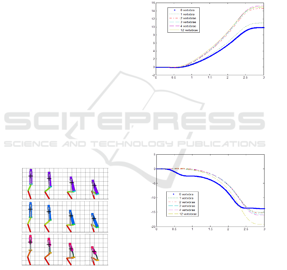
Table 1 gives masses and heights of the different
parts. The trunk is composed of a thorax and a lumbar
part. Foot mass was taken into account in the tibias.
Arms are connected to the shoulders at the top of the
thorax.
In order to investigate the influence of the number
of vertebrae on pick up an object from the floor, a dy-
namics study of the model in the sagittal plane was
conducted in (M. Souissi, 2011). The motion algo-
rithm uses the pseudo-inverse technique.
The input trajectory to be tracked is defined as
F = [x
G
,x
pelvis
,z
pelvis
,θ
pelvis
] (1)
Given the input above, the algorithm computes all
joint angles (β
i
):
• At t=0, calculate initial β
i
t=0
, F
t=0
, and Jacobian
J
t=0
.
• For each next position F
next
of input trajectory,
1. ∆F ← F
next
- F(t).
2. Calculate pseudo-inverse J
+
from Jacobian J.
3. ∆β ← J
+
∆F.
4. β(t + ∆t) ← β + ∆β.
5. Calculate F(t + ∆t) using β(t + ∆t) from for-
ward geometric model.
6. Calculate Jacobian J using β(t + ∆t) for next
step.
Where F is the force applied by segment i to i− 1, and
(β
i
) is the joint angle, between segment i − 1 and i.
2.2 Simulation and Results
-0.2 0 0.2 0.4
0
0.2
0.4
0.6
0.8
1
1.2
1.4
0 0.2 0.4
-0.2 0 0.2 0.4 0.6
-0.2 0 0.2 0.4 0.6
-0.2 0 0.2 0.4 0.6
0
0.2
0.4
0.6
0.8
1
1.2
1.4
0 0.2 0.4
0.6
-0.2 0 0.2 0.4 0.6
-0.2 0 0.2 0.4 0.6-0.2 0 0.2 0.4 0.6
-0.2 0 0.2 0.4 0.6
0
0.2
0.4
0.6
0.8
1
1.2
1.4
0 0.2 0.4
0.6
-0.2 0 0.2 0.4 0.6
-0.2 0 0.2 0.4 0.6
0.6
0.6
0 vertebra
1 vertebra
12 vertebrae
(a)
(b)
(c)
X(m)
Z(m)
Figure 3: Knee flexion to pick up object on floor. This mo-
tion lasts 3 [sec]. x
pelvis
= 0.19[m] and z
pelvis
= 0.2[m]. (a)
0 vertebra, (b) 1 vertebra and (c) 12 vertebrae.
The experiment consists of pick an object from the
floor (Fig. 3). This simulation aims to determine the
influence of the number of vertebra pitch joints in
matter of sum of work in vertebrae and the inclination
of thorax after motion. The cervical region, sacrum
and coccyx are fixed. The vertebrae are placed in
the lumbar and thoracic region between the first lum-
bar vertebra and the 7th vertebra of thorax, the region
most affected by the (AIS). The experiment was car-
ried out with 0 vertebra, with 1 vertebra and with 12
vertebrae in the spine.
Time(s)
Inclination (deg)
Inclination (deg)
Figure 4: Inclination (degrees) of thorax in flexion of knees
to pick up an object from the floor.
Fig. 4 shows the thorax inclination for differ-
ent number of pitch joints. The inclination of trunk
increases significantly when the number of vertebra
joints increases. From 12 joints, there is an increase
of nearly 50% of thorax inclination compared with the
configuration without articulated spine.
Time(s)
Work (j)
Figure 5: Spine work in the knee flexion.
Fig. 5 shows the work in spine for 0, 1, 2, 3, 4 and
12 vertebrae. The work is less important for a col-
umn composed of a single joint. The more vertebrae,
the more the work increases. For 12 vertebrae work
reaches 19[ j].
Simulation experiments carried out in the sagittal
plane have shown that pitch joints in the vertebral col-
umn is so important. Rigid brace can limit the mo-
Dynamic Simulation of Vertebral Column and Control of the Posture using a Parallel Mechanism
19
tions of kid. According to experiments we propose to
work with 12 joints placed in the trunk.
3 DYNAMIC SIMULATION OF
SPINE
3.1 Dynamics
Fig. 2 shows the actuation planes. In this section the
conterclockwise torque T
a
about center of mass pro-
duced by the applied force F
a
is calculated:
T
a
= F
a
.L
T
(2)
Where L
T
is the length of child from center of
mass to head and equal to 0.50[m].
The opposite restoring torque T
b
due to the upper
body’s weight is:
T
b
= P.D (3)
Where D is the diameter of waist and assuming that
the mass of upper body of the child is 20[kg], his
weight P is:
P = 20.9.8 = 196[N] (4)
for D = 0.101[m] and T
b
= 19.8[N.m]. The restoring
torque produced by the weight of upper body is there-
fore [N.m]. Trunk is on the verge of toppling when
the magnitudes of these two torques are equal; that is:
T
a
= T
b
(5)
So the force required to move trunk of child in sagittal
plane is :
F
a
= T
a
/L
T
= 19.8/0.30 = 39.6[N] (6)
Regarding equation (6) force F
a
depends on the dis-
tance between the center of mass and the point of ap-
plication of force. If F
a
is near of the center of gravity,
torque will be so important. And since the center of
mass is close to the lumbar part, the force at the level
of the lumbar vertebrae is the most important, which
explains the dimensions of the vertebrae at this level
comparing with the cervical and thoracic vertebrae.
For L
T
= 0.1[m], torque is equal to F
a
= 198[N] By
bending the torso the center of gravity will be shifted
away and as the result will the restoring torque be in-
creased.
3.2 A Cad Model for Motion Simulation
In this paper a new model is proposed for the lum-
bar part of a spine. In this model we consider that
all solicitations of the spine are vertically applied at
the center of the vertebra. The 3D model has been
elaborated in ADAMS-software with the aim to run a
dynamic simulation for computing motion properties
and reaction forces (Fig. 6). In ADAMS-software the
discus has been modeled as a body that is attached
to the assembled vertebrae. Joint between all discs is
spherical. This joint is very near to the real type of
link between vertebrae.
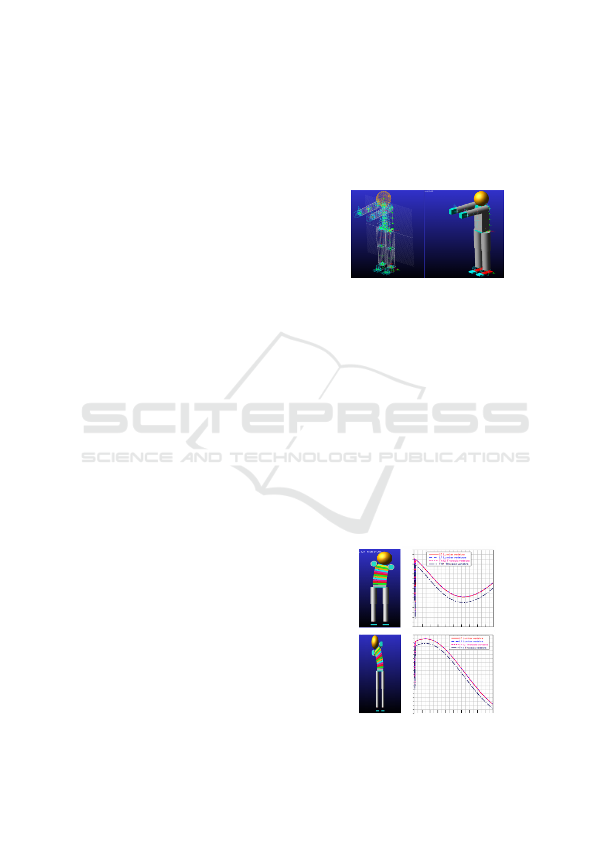
Figure 6: A 3D ADAMS model of all body. Masses and
heights of the different body parts are derived from a human
kid-size model.
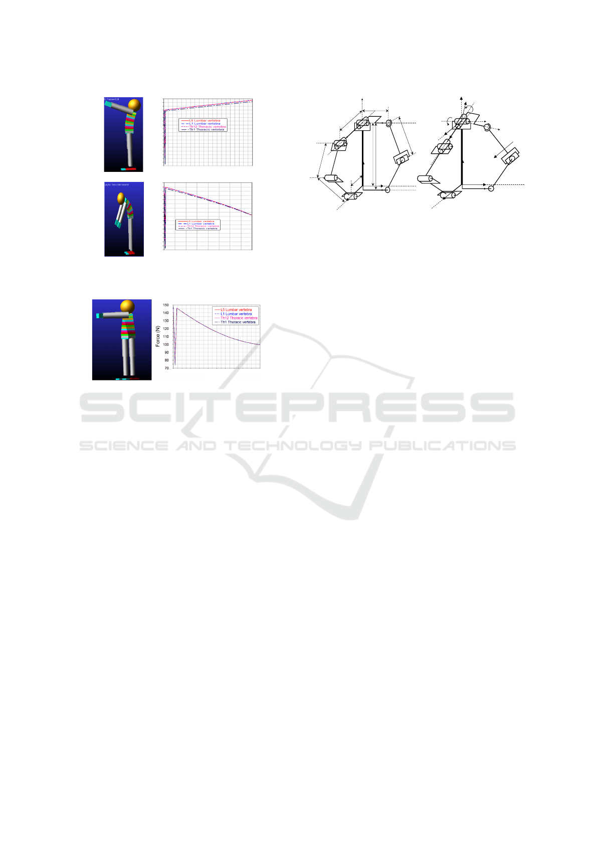
First simulation consists of tilting the entire body
to the right and left and calculating the forces applied
to the column in the thoracic and lumbar region. Fig.
7 shows the simulation with ADAMS-software and
the result of forces applied in vertebrae for the left
bending motion. Regarding the simulations, forces
applied to the thoracic and lumbar vertebrae vary be-
tween 130[N] and 107[N] for the left bending motion.
Results correspond to the equation (6). When the dis-
tance between force and vertebra is small, the magni-
tude of force is more important.
Second simulation consists of the for-
ward/backward motion. Fig. 8 shows the simulation
with ADAMS-software and the result of forces ap-
plied in vertebrae for the forward motion. Forces vary
between 300[N] and 350[N]. And third simulation
consist of the yaw motion. Forces applied to the
vertebrae reachs 145[N].
0 1 2 3 4 5 6 7 8 9 10
Time (10
-2
s)
135
130
125
120
115
110
105
100
95
Force (N)
0 1 2 3 4 5 6 7 8 9 10
Time (10
-2
s)
95
135
130
125
120
115
110
105
100
95
Force (N)
90
85
(a)
(b)
Figure 7: Forces applied to the vertebrae for the left/right
bending motion.
ICINCO 2017 - 14th International Conference on Informatics in Control, Automation and Robotics
20
0 1 2 3 4 5 6 7 8 9 10
Time (10
-2
s)
Force (N)
350
340
330
320
310
300
290
280
270
260
0 10 20
Time (10
-2
s)
Force (N)
340
330
320
310
300
290
280
270
260
(a)
(b)
Figure 8: Forces applied to the vertebrae for the (b) forward
(c) backward motion.
0
1
2
3
4
5
6
7
8
9
10
Time (10
-2
s)
Figure 9: Forces applied to the vertebrae for the yaw mo-
tion.
In the next section we propose a parallel mech-
anism to correct the abnormal posture change along
the length of the curve, taking into account the max-
imal forces applied in vertebrae in the three planes,
pitch, roll and yaw motions.
4 PARALLEL TILTING MODULE
FOR CORRECTING POSTURE
4.1 Kinematic Model
In this section we propose a dynamic brace to treat
children with scoliosis without limiting upper body
movement. Mechanism is fixed close to the verte-
brae L1, L2, L3, L4 and L5. This choice is due to
the opti- mization of mechanism in matter of torque
applied to the two motors fixed in the bottom plat-
form (M. Souissi, 2016). The objective of this sys-
tem is to modulate the corrective forces on the spine
in desired directions while still allowing the users to
perform typical everyday activities. The most impor-
tant motions to control are the pitch, roll and yaw mo-
tions in the actuation planes. Mechanism proposed
was simulated with ADAMS. It is fixed in the lum-
bar region. The parallel mechanism, developed in
k
O
A
1
B
2
B
3
B
1
A
2
A
3
C
j
i
h
1
h
2
ℓ
1
ℓ
2
ℓ
3
ℓ
4
d
1
d
2
d
3
d
4
k
O
A
1
B
2
B
3
B
1
A
2
A
3
C
j
i
θ
10
θ
21
i'
i
j'
j
k
k'
u
(a)
(b)
Figure 10: (a) Perspective view of parallel mechanism in
initial position. The central rod is fixed and rigid. It is at-
tached to the top platform by a Universal joint at O. The
mechanism is actuated by two revolute joints, each of them
is located at the bottom of each arm. The two arms are ar-
ranged at 90 [deg]. The arm A
1
A
2
A
3
is planar and remains
in the (xz) remains in this plane. It is composed of two rev-
olute joints and one U-joint. The other arm B
1
B
2
B
3
is ini-
tially in the (yz) plane, and does not remain in this plane if
the top platform rolls. (b)Perspective view of parallel mech-
anism after pitch and roll rotations.
(M. Souissi, 2012a) and compared with serial system
in (M. Souissi, 2012b), is inspired from a flight simu-
lator (Sabrie, 2004) and (Alexander V. Korobeynikov,
). It consists of 2 platforms – one bottom platform
CA
3
B
3
and one top platform OA
1
B
1
, that are linked
by a central vertical rod CO and two arms arranged at
90[deg] in the initial position (Fig. 10). The central
rod CO is fixed and always remains vertical. It joins
the top platform through a Universal joint whose drive
is responsible for roll and pitch motion of the top plat-
form. The arm A
1
A
2
A
3
is planar and is composed of
two segments, two revolute joints at A
2
and A
3
, and
one Universal joint at A
1
. This is the planar arm. The
arm B
1
B
2
B
3
also includes two segments, one revolute
joint at B
3
, one Universal joint at B
2
and one ball joint
at the attachment locus B
1
with the top platform. This
arm is 3D. The bottom platform is linked to coordi-
nate frame R
0
, centered at C with axes i, j and k.
The top platform rotates about O and is linked to co-
ordinate frame R
0
, frame centered at O whose axes are
i
0
, j
0
and k
0
(Fig. 10). The top platform can be pitched
about fixed axis j by angle θ
10
, and rolled about axis
i
0
by angle θ
21
.
The two active joints are the revolute joints at A
3
and B
3
. The associated rotation angles are denoted by
α and β.
The length d
4
and `
4
are approximately half the
lengths d
1
and `
1
respectively.
This means that the motor axes should be located
in the middle with respect to the trunk half width and
the trunk half depth respectively.
Dynamic Simulation of Vertebral Column and Control of the Posture using a Parallel Mechanism
21
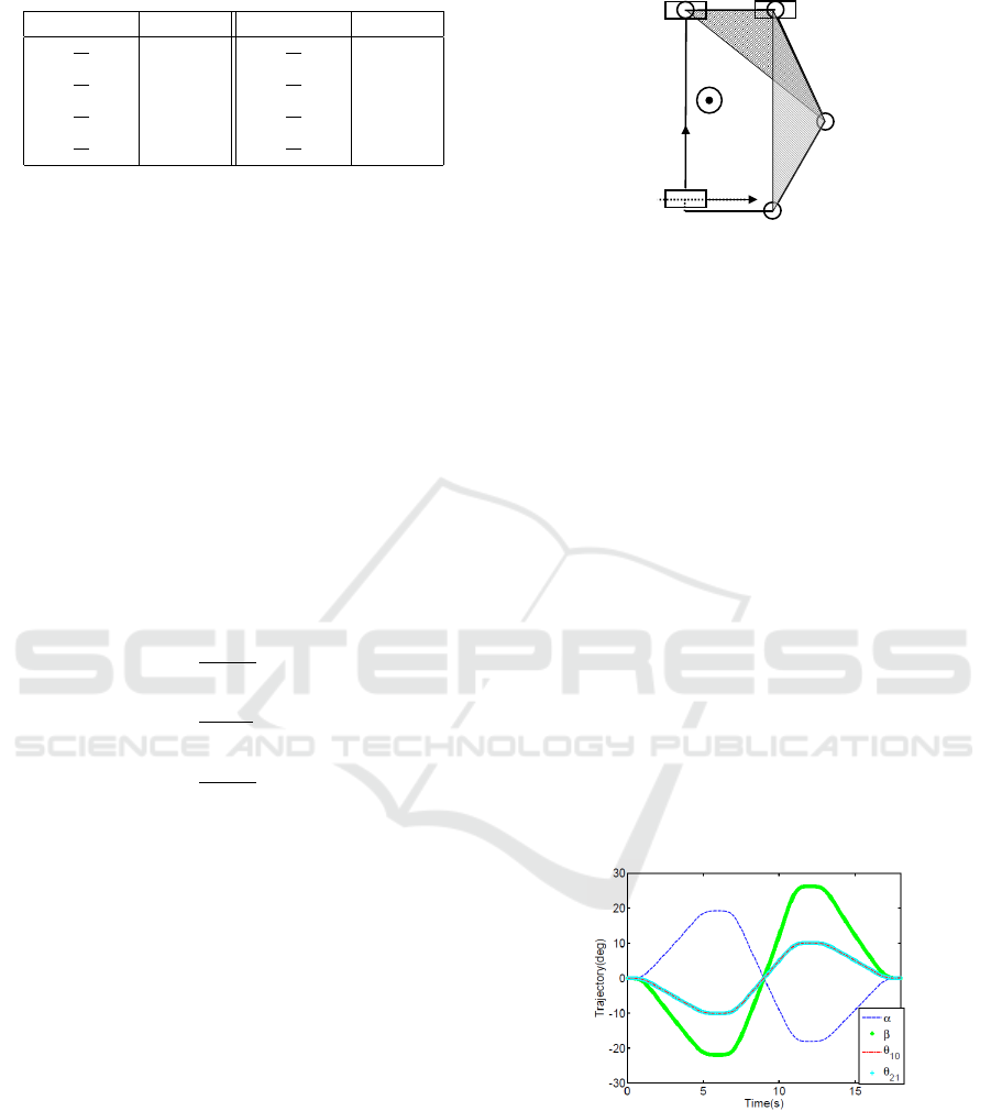
Table 2: Normalized parameters of 3D and 2D arm.
Parameter 2D arm Parameter 3D arm
l
1
h
1
2
d
1
h
1
1
l
2
h
1
0.666
d
2
h
1
0.666
l
3
h
1
0.733
d
2
h
1
0.466
l
4
h
1
1.333
d
4
h
1
0.666
4.2 Torque Considerations
The actuators will have to support the mass M of the
bottom platform. Assuming this mass is concentrated
on a point G that is fixed with respect to the bottom
platform, we can express the torques τ
1
and τ
2
that
the actuators must exert to support this mass:
τ
1
τ
2
= J
T
τ
S
1
τ
S
2
(7)
where J is the Jacobian matrix of forward kinematics:
˙
θ
10
˙
θ
21
= J
˙
α
˙
β
J =
r
1
0
−r
1
r
3
r
2
r
1
=
A
3
A
2
u
A
2
A
1
j
OA
1
u
A
2
A
1
j
r
2
=
B
3
B
2
u
B
2
B
1
i
OB
1
u
B
2
B
1
i
0
r
3
=
OB
1
u
B
2
B
1
j
OB
1
u
B
2
B
1
i
0
τ
S
1
= MOGg j
τ
S
2
= MOGgi
0
where g is the gravity, r
1
, r
2
and r
3
are expressed
thanks to the scalar triple product of three vectors.
The vectors of the type u
XY
are unit vectors along the
direction given by the pair of points X and Y. τ
S
1
and
τ
S
2
are the gravity torques exerted at the center O of
the bottom platform, respectively about the axis j and
the axis i
0
.
Let us give a geometric interpretation. If r
3
= 0,
i.e. actuators are activated separately,we have:
τ
1
= r
1
.τ
S
1
τ
2
= r
2
.τ
S
2
The ratios r
1
and r
2
can be interpreted respectively as
the ratio of the area of the triangle A
1
A
2
A
3
over the
triangle OA
1
A
2
(Fig. 11), and the ratio of the area of
the triangle B
1
B
2
B
3
over the triangle OB
1
B
2
.
To reduce the active torques in the parallel mech-
anism, it is therefore necessary to reduce these two
O
A
2
A
3
A
1
i
k
C
j
Figure 11: Geometric interpretation of the ratio of the active
torque at A
3
over the gravity torque at O. According to the
scalar triple product expression, it is equal to the surface of
the triangle A
1
A
2
A
3
over the surface of the triangle OA
1
A
2
.
ratios as much as possible. This can be achieved by
a careful choice of the different lengths (`
i
) of the
mechanism, and considering the full scope of incli-
nations required from the specifications of the tele-
echography application. Intuitively through the ge-
ometrical interpretation, the surface of the triangle
A
1
A
2
A
3
should be reduced compared to the trian-
gle OA
1
A
2
. This can be achieved by increasing the
length A
1
A
2
over A
2
A
3
, and increasing the length OA
1
from OC. However, one may pay attention not to go
through flat triangle configurations that represent sin-
gularities where the mechanism would not be control-
lable any more.
The motion consist of giving the angular inputs
for the pitch/roll joint of the top platform, namely θ
10
and θ
21
. The vertebral column is bent 10[deg] for-
ward, then 10[deg] backward. The angles for the joint
motors, namely α and β are calculated thanks to the
inverse geometric model (Fig. 12).
Figure 12: Angle trajectories θ
10
and θ
21
of platform and
the related motor angles α and β for the pitch inclination
motion.
4.3 Simulations and Result
The prototype was simulated with ADAMS-software
and trajectory planning is designed with Matlab-
SIMULINK, which is used to control the ADAMS
ICINCO 2017 - 14th International Conference on Informatics in Control, Automation and Robotics
22

(a)
(b)
3
21
0
10
9
8
7
6
5
3
21
0
10
9
8
7
6
5
Torque (N.m)
Torque (N.m)
(b)
Time(s)
Time(s)
(L1)
(L2)
(L3)
(L4)
(L5)
)
(L1)
(L2)
(L3)
(L4)
(L5)
)
Figure 13: Prototype used to correct the posture in the sagit-
tal(a) and coronal(b) plane.
model (M. Souissi, 2012b), minimization of torque
was done in (M. Souissi, 2016). Prototype is used to
correct the posture of the spine in two planes: sagittal
and coronal plane.
For all experiences done with ADAMS, the sagital
plane is presented by zy-plane, the axial plane is pre-
sented by xy-plane and the coronal plane is presented
by xz-plane as shown in figure (Fig. 2) .
Fig. 13 shows the torque of the two motors of roll
and pitch joint to move spine in the sagittal and coro-
nel plane. Maximal torque of the 3D arms is 10[N.m]
and torque of the 2D motor is constant and is about
6[N.m] in the first experience. Maximal torque of the
3D arms is 10[N.m] and torque of the 2D motor is con-
stant and is about 8[N.m] in the second experience.
5 CONCLUSION AND
PERSPECTIVES
In this paper, a model for the human spine is pro-
posed for analyzing applied forces on the interverte-
bral discs through a suitable motion simulation. A
new dynamic brace has been proposed to correct the
posture of the human affected by scoliosis in two
planes, sagittal and coronal plane. The next steps of
this research will consist realization and motorization
of system according to the dynamics results obtained.
REFERENCES
A. H. W. V. Eeuwijk, S. Lobregt, F. A. G. (2006). A
novel method for digital x-ray imaging of the com-
plete spine. 344.
Abbott, J., Nagy, Z., Beyeler, F., and Nelson, B. (2007).
volume 3.
Alexander V. Korobeynikov, V. E. T. Modeling and evalu-
ating of the stewart platform.
Anderson, S. M. (2007). Spinal curves and scoliosis, radio-
logic technology. 79.
Aulisa, A.G., G. V. M. E. G. M. F. F. and Aulisa, L. (2014).
Brace treatment in juvenile idiopathic scoliosis: a
prospective study in accordance with the srs criteria
for bracing studies-sosort award 2013 winner.
Behairy, Y., H. D. H. D. M. J. M. M. (2000). Partial correc-
tion of cobb angle prior to posterior spinal instrumen-
tation. 20:398–401.
Cobb, J. (1984). Outline for the study of scoliosis. 5:261–
275.
Delorme, S., L. H. P. B. R. C. C. C. J. (2000). Pre-, intra-
, and postoperative three-dimensional evaluation of
adolescent idiopathic scoliosis. 13:93–101.
J. Zhang, E. Lou, L. H. L. D. L. H. J. V. R. Y. W. (2009). Au-
tomatic cobb measurement of scoliosis based on fuzzy
hough transform with vertebral shape prior. 22:463–
472.
Lafage, V., D. J. L. F. S. W. (2004). 3d finite element simu-
lation of cotreldubosset correction. 9:17–25.
Longstein, J. (1994). Adolescent idiopathic soliosis.
344:1407–1412.
M. Souissi, V. Hugel, P. B. (2011). Influence of the number
of humanoid vertebral column pitch joints in flexion
movements.
M. Souissi, V. Hugel, P. B. (2012a). Design optimization of
parallel joint mechanism for humanoid spine. pages
997–1000.
M. Souissi, V. Hugel, P. B. (2012b). Modeling and simula-
tion of humanoid robot spine vertebra. 2:415–418.
M. Souissi, V. Hugel, P. B. (2016). Minimized-torque-
oriented design of parallel modular mechanism for hu-
manoid waist.
Sabrie, E. (2004). Analyse d’un m
´
ecanisme de simulation
de vol sph
´
erique et son contr
ˆ
ole en temps reel. Facult
´
e
des sciences et de g
´
enie universitaire, Laval, Qu
´
ebec.
Schiller, J.R., T. N. and Eberson (2010). Brace management
in adolescent idiopathic scoliosis. 468:670–678.
Dynamic Simulation of Vertebral Column and Control of the Posture using a Parallel Mechanism
23
