
Lessons Learned on using Execution Model Implementation
in Sparx Enterprise Architect for Verification
of the Topological Functioning Model
Viktoria Ovchinnikova and Erika Nazaruka
Department of Applied Computer Science, Riga Technical University, Sētas iela 1, LV-1048, Riga, Latvia
Keywords: Execution Model, UML, Modeling Tools, Topological Functioning Model.
Abstract: The execution model can improve analysis, testing and verification of software systems and their features
right from the early stages of development. It helps to decrease risks and the possibility of future defects.
One of the main goals and challenges for modern modeling tools is the ability to generate usable source
code using the modeling approach. The system functionality can be shown as Topological Functioning
Model and this functionality can be validated with the help of modeling tools. The paper presents an
overview of modeling tools for the execution of models and the ways that they can aid software
development. Four modeling tools are reviewed and compared based on their features and documentation –
Cameo Simulation Toolkit, Enterprise Architect, Papyrus with Moka and BridgePoint. Two of them –
Cameo Simulation Toolkit and Enterprise Architect, are analyzed and compared in practice. Results of the
overview are the base for future work, where the tools will be applied for case studies.
1 INTRODUCTION
One of the first steps of software development is
requirements analysis, where the goal is to specify
the system structure and behavior. Usually at this
stage requirements are represented in the form of
unstructured text and structured descriptions that
later become the system documentation. Both the
creation and reading of such documentation is a
time-consuming process. Modeling approaches can
be used to help decrease this time since they can
serve as a blueprint and the documentation
simultaneously. Either way, the specification must
bridge the problem and the solution domains. The
Topological Functioning Model (TFM) can be used
to achieve this goal (see Section 2.2).
However, if we put effort into modeling, the
result must be trustable. To save resources the model
needs to be automatically or manually verified
before implementation. The verification can be
performed by using execution models, which can
also be transformed to source code. The execution
models and the supporting modeling tools aim to
perform the generation without writing a single line
of actual code.
The research hypothesis is that the execution of
models and mentioned modeling tools can help in
model (especially the TFM) verification and
decrease future risks of implementation errors, while
not severely complicating the resulting model or
requiring significantly more time and other resource
investments.
The main goal is to study the main approaches of
model verification and overview the characteristics
of modeling tools that support execution of models
and can be potentially used for verification of TFM
(through transformations to UML at this stage of
research). Four tools that support execution of
models have been selected - Cameo Simulation
Toolkit, Enterprise Architect, Papyrus with Moka
and BridgePoint. To accomplish this goal the
following tasks need to be done: review execution
models and their purpose; research information
about modeling tools available as well as the official
websites of these tools; summarize the results and
analyze benefits and the usability of selected
modeling tools in the software system development
process.
The current work is focused on the tool
Enterprise Architect that is examined in practice in
section 3. Cameo Simulation Toolkit has been
Ovchinnikova, V. and Nazaruka, E.
Lessons Learned on using Execution Model Implementation in Sparx Enterprise Architect for Verification of the Topological Functioning Model.
DOI: 10.5220/0006388403550366
In Proceedings of the 12th International Conference on Evaluation of Novel Approaches to Software Engineering (ENASE 2017), pages 355-366
ISBN: 978-989-758-250-9
Copyright © 2017 by SCITEPRESS – Science and Technology Publications, Lda. All rights reserved
355

previously analyzed in practice in (Ovchinnikova &
Nazaruka, 2016) and the remaining tools (Papyrus
with Moka and BridgePoint) are left for further
research. Their descriptions and characteristics are
based only on documentation and other available
information.
Section 2 presents the background of the
research and related work – the TFM within the
Model Driven Paradigm, execution UML in brief
and modeling tools for execution models. Section 3
reviews tools for execution models and current
results. Section 4 discusses the results and states
further research tasks.
2 BACKGROUND
2.1 Related Work
Different techniques of model checking and
verification exist and have been researched in the
related works.
The authors of (Donini et al., 2006) use
techniques of model checking for performing
automated verification of UML design of a web
application. The focus is on black-box verification.
They propose a UML design checking method to
check the correctness of the design. The method
automates the checking of a system model with its
specifications, which is expressed in a logical
formalism. Model checking in this case is automated
and does not need any user interaction, while tests or
other formal methods can require user interaction.
Finally, a system to automatically build the
Symbolic Model Verifier (SMV) model was
implemented, which can be verified according to
system specifications. Specifications are presented
as Computation Tree Logic (CTL) formulas. Formal
verification helps to ensure the correctness and
accuracy of software system. It is based on static
analysis. As authors explained, the CTL can be used
to verify properties of the graph of the web
application, in which arcs are state transitions and
nodes are states.
The statistical approach is surveyed and its
advantages: simplicity, uniformity and efficiency,
are analyzed in (Legay et al., 2010). For verifying
quantitative properties of stochastic systems, the
numerical and simulation-based approaches can be
used. The model checking of stochastic systems can
be done by a numerical approach to compute or
approximate an exact measure of paths by using
formulas and a specific algorithm. Another approach
is to use simulation of the system to have a large
number of executions and use hypothesis testing to
know whether results provide a statistical evidence
to check the compliance of requirements to the
specification. Only systems with certain structural
properties can be checked by using numerical
algorithms. The authors suggest that simulation-
based approach cannot get a definitely correct result
in comparison with numerical approach. Statistical
model checking approach can be used for getting
estimates of the probability measure on executions.
Statistical model checking can be applied to the
greater number of systems in comparison with
numerical approach, but it provides only
probabilistic results and does not guarantee the
correctness of the answer received from the executed
algorithm.
Authors in (Milewicz & Pirkelbauer, 2017) tried
to produce a categorical and quantitative model of
thread behaviors. Different threads can produce
different combinations due to concurrency and it is
complicated for a tester to repeat or determine
concurrency bugs. They define a thread as a
sequence of the blocks of instructions that are
related. Their aim is to determine potential
concurrency bugs which can happen during
execution of parallel threads. The model checking
can precisely define and find how, where and when
violations can occur. The authors used heuristics to
detect the potential bugs (e.g. deadlock detection,
count of times that the current thread has been
scheduled and count of other possible threads that
can be scheduled instead). The approach allows to
analyze and detect possible bugs quicker and at a
reduced cost.
Combined logics and approaches involving
different dimensions are considered by authors of
(Konur et al., 2013). They do not introduce a new
logic for model checking of multi-agent systems.
Instead they show a modular approach, created from
the combined logics, that introduces a generic
method of model checking and presents different
aspects similar to other approaches for multi-agent
systems. They combine temporal, real-time and
probabilistic logics and provide some expressions in
the paper.
The design of a composite web service is verified
by authors in (Bentahar et al., 2013). They divide
behaviors into two abstraction levels: control and
operational. Control is application-independent and
monitors the progress of execution of the operational
behavior (it identifies the actions and constraints).
Operational is application-dependent and defines the
business logic, specifies functions, which should be
performed by the Web service. Both of them are
MDI4SE 2017 - Special Session on Model-Driven Innovations for Software Engineering
356
linked together in order to check that the sequence of
actions called by operational behavior is always
synchronized with the control behavior.
Methods analyzed in (Donini et al., 2006),
(Legay et al., 2010), (Milewicz & Pirkelbauer,
2017), (Konur et al., 2013) and (Bentahar et al.,
2013) are based on heuristics, probabilities and use
formulas – it is not suitable for the goal of the
current paper, where all traceable paths must be
traced.
Model-checking can be used in the next step of
verification, when more complex logic must be
checked, such as concurrent threads. For model
design and for analytical models, simulation models
and techniques are sufficient. Execution model can
provide this simulation and simple verification of
these models (See Section 2.3).
Various authors describe their experience with
modeling tools that support execution models. The
author of (Cabot, 2017) shows tools that support
execution models – some of them implement the
fUML standard. The authors of (Micskei et al.,
2014) review open source tools which use fUML
and Alf for execution models. They summarize their
experience of using various open source tools
(fUML Ref. Impl., Moka, Moliz, Alf Ref. Impl. and
Papyrus Alf Editor). Authors of (Seidewitz &
Tatibouet, 2015) describe how to combine Alf with
UML and showcase this combination with a working
example in Papyrus. They suggest that Moka can be
used for successful execution of the obtained model.
The information can help in the future research
when all the compared tools will be reviewed in
action - (Micskei et al., 2014) demonstrates
advantages and drawbacks of various modeling tools
by example, while information from (Seidewitz &
Tatibouet, 2015) can help to familiarize with Alf
semantics.
2.2 The Topological Functioning
Modeling within Model Driven
Paradigm
The TFM can be presented as a Computation
Independent Model (CIM) in Model-Driven
Architecture (MDA) (Asnina & Osis, 2011). It is
able to provide the continuous mappings between
TFMs of the solution and problem domain in the
CIM level (Asnina & Osis, 2010), (Osis & Asnina,
2015).
It can be visualized as a directed graph with
vertices (functional features) and edges (cause-and-
effect relations) between them. Names in human
understandable language are assigned to the
functional features and they define the system
processing and characteristics. The process of the
TFM obtainment from the software system
description is overviewed and described by
examples in (Osis & Donins, 2010). The IDM
toolset (Osis & Donins, 2010), (Fernandez Cespedes
et al., 2015) gives opportunity to obtain TFM
automatically from the business use case
descriptions (Osis & Slihte, 2010), (Slihte et al.,
2011) and to supplement it. Also, TFM is compared
with another business model such as Business
Process Model and Notation (BPMN) in (Osis &
Solomencevs, 2016).
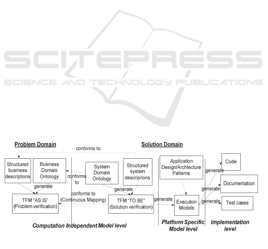
The global context of the research is the co-use
of agile methods, model-driven methods and the
TFM (Figure 1). The main goal of the agile methods
is running code. System usability is achieved by
incremental development with short iterations and
close cooperation with customers.
Figure 1: The TFM and Execution Models within Software Development.
Lessons Learned on using Execution Model Implementation in Sparx Enterprise Architect for Verification of the Topological Functioning
Model
357

The model-driven methods allow design models
simulation as well as code and documentation
generation. Application of the TFM and execution
models with agile principles should increase system
usability and decrease development costs.
As authors in (Osis & Donins, 2010), (Donins et
al., 2011), (Solomencevs & Osis, 2015) suggest, the
topological diagrams (supplemented UML
diagrams) transformed from the TFM can be
presented as a Platform Independent Model (PIM) in
the MDA. The authors provide stepwise
transformation mappings between TFM and
topological UML diagrams elements. This
transformation is the basis for the TFM
transformation to Execution Models described.
The survey of TFM evolution history is available
in (Solomencevs, 2016).
2.3 Execution Models in Brief
There are two similar terms – “execution model”
and “executable model”. Authors want to distinguish
both terms and define their meanings as they are
used in this research.
In the authors’ opinion, executable models are
models that execute by themselves or automatically
without any human interaction during execution. Its
execution logic can be presented at the beginning
before execution. It helps to analyze and test
software system logic and traceability as an
executable model. The 100% working target source
code can be generated from the executable model,
without adding any lines of source code to it. It is
the future of software system development and the
future plan of executable models. The main aim for
executable model is the development of software
systems using only modeling.
The execution models are models that execute
with human help, for example, by choosing the next
step (guard) in the model during execution. Target
source code can be generated from execution model,
but it will not be complete and needs to be
supplemented. In many situations the software
systems are complex systems with difficult to
understand logic. Currently, execution models can
represent only simple logic of software systems, for
example: tracing objects through operations, set and
get object data, declare and instantiate the object.
This is the type of models that this research is
focused on and there are currently no tools for
executable models publicly available.
In a real software system human interaction is
necessary, for example to enter input data or to
choose the next step (by clicking a computer mouse
button in the graphical user interface or in some
other way). It is also possible to write some
automatic tests for automatically checking the
behavior of some functionality in this software
system without any human interaction. It can be said
that automatic tests have similar meaning as
executable models have, because it executes without
human action during its execution.
Modeling using execution models can be used as
a form of agile modeling, using the Agile
Methodology (Atlassian, 2017). Execution models
provide creation templates of executed systems
allowing testing (independent of the user interface)
and verification according to system requirements at
the early stages of system analysis. The processes
can be modeled and become traceable before their
actual implementation. Defects, unused objects and
other problems can be noticed early on and resolved.
Two types of the execution models exist -
Executable UML (xUML) (also known as
Executable and Translatable UML (xtUML))
(xtUML, 2012) and Foundational subset for the
execution UML models (fUML) (OMG, 2016).
They use simplified UML diagrams (e.g. in the class
diagram some types of relationships are not used),
but with formal action semantics. State machine and
activity diagrams are used for specifying the
behavior of the system. The Object Action Language
(OAL) is used in xtUML and the action language for
fUML (Alf) is used in fUML for modeling the
processes in the system.
3 COMPARISON OF MODELING
TOOLS FOR EXECUTION
MODELS
Modeling tools that support execution of models aim
to represent the executable and traceable behavior of
the system. The tools try to decrease the need for
writing code and represent all the necessary
behavior, objects and instances as an execution
model.
3.1 Modeling Tools for Execution
Models
In order to understand mandatory conditions for the
target model content and presentation format in the
transformation algorithm from the TFM to an
execution model, Cameo Simulation Toolkit
(NoMagic, 2017), Enterprise Architect
(SparxSystems, 2017), Papyrus with Moka (Rivet et
MDI4SE 2017 - Special Session on Model-Driven Innovations for Software Engineering
358

al., 2014), and BridgePoint (xtUML, 2017) tools are
compared with each other using criteria that have
been defined by the authors as necessary for
successful integration into the software development
process and the potential verification of the TFM:
Integration with the Eclipse framework. Eclipse is
one of the most used modeling and programming
frameworks (Hamilton, 2014). The author
considers this an opportunity, because the TFM
toolset (Slihte, 2015) is also implemented on the
same platform and the tools can be potentially
used together.
Import/Export capabilities. Which information
can be imported to and exported from the tool?
This criterion is important if one needs to move
information from one tool to another, which is
necessary both to the software development
process and the verification of TFM.
Supported diagrams in the execution model. It is
necessary to know which diagrams of UML can
be used as the execution models in these tools for
further analysis. In the context of TFM this means
which diagrams the TFM can be transformed into.
Manual enhancement of UML diagrams. Adding
additional information or behavior of some
actions required for execution is not always
possible using standard UML diagrams.
Source code generation. Can be source code
generated directly in this tool? This criterion is
important both for the software development
process and the verification of TFM if the tool
generates usable code that is potentially more
complete than the code generated from non-
execution models.
Execution process. How the execution process is
represented? How to provide the objects and its
instances traceability through the diagrams? How
to determine and choose the next action, when the
current action is completed?
Table 1 shows comparison results of tools by the
criteria “Integration with Eclipse”, “Import”,
“Export”, “Supported UML diagrams” and “Source
code generation”. Manual enhancement and
execution process is compared under Table 1.
Cameo Simulation Toolkit uses the fUML
standard. The additional inside activity diagrams or
scripts needs to be created or written for some
activity in the diagram in order to manage objects. In
Enterprise Architect scripts written in JavaScript
need to be presented for providing the behavior of
actions, choosing the next step (action) and
managing objects. Papyrus with Moka uses fUML
standard and behavior of actions is provided in the
form of activity diagrams. BridgePoint uses xtUML
standard and OAL execution rules. Behavior of any
type of action needs to be written in OAL language.
Simulation of model execution is visualized in
the mentioned tools. The execution process can be
manual, during debugging (using breakpoints) or
automated, choosing the appropriate decision for the
next step if necessary. The information of execution
(e.g. object data, an executing action name) is shown
in the console during execution. It is possible to
define one main input (execution start) and output
(execution end). Objects can be managed and traced
through the model and their values can be changed.
Cameo Simulation Toolkit and Enterprise
Architect are commercial tools and provide more
possibilities for import and export. They also
provide the possibility of generating a template of
the user interface (with buttons, windows), using
only the execution model without writing any actual
code and execute the model using this generated
user interface.
The UML activity diagram is used to provide the
behavior of actions in Cameo Simulation Toolkit
Table 1: Tool comparison.
Tools\ Criteria
Integration
with Eclipse
Import Export
Supported UML
diagrams
Source code
generation
Cameo
Simulation
Toolkit
Standalone
tool
UML, XMI,
CSV and other
UML, CSV
and other
Sequence, state
machine, class and
activity diagrams
Not documented
Enterprise
Architect
Standalone
tool
XMI, CSV XMI, CSV
State machine, activity
and sequence diagrams
Not documented
Papyrus with
Moka
Integrated
with Eclipse
Only Papyrus
models
Not
documented
Activity diagram Not documented
BridgePoint
Standalone
tool
Only
BridgePoint
projects
Only
BridgePoint
projects
Component, class and
state machine diagrams
Can be translated
if behavior is in
OAL
Lessons Learned on using Execution Model Implementation in Sparx Enterprise Architect for Verification of the Topological Functioning
Model
359

and Papyrus with Moka, because they both use
fUML standard. The UML state machine diagram
with defined behavior is used for execution models
in BridgePoint which uses xtUML standard and
OAL language to define the behavior of actions.
Tools provide a visual simulation of the execution
process and the possibility to log the process
information to the console. Documentation of the
tools only provides the basic introductory
information - it is challenging to present all
necessary information for all kinds of users with
different aims and goals.
In summary, all of the tools reviewed make
modeling safer by aiding in the early discovery of
potential mistakes. Cameo Simulation Toolkit,
Enterprise Architect and Papyrus with Moka tools
also provide a debugging mode, which allows
interactive viewing of the system functionality using
a step by step approach. Object management can
help to determine, discover and correct the weak
spots in the system before the actual
implementation.
3.2 Comparison of Execution UML
Diagrams
The current work further focuses on the tool
Enterprise Architect. For more information about
Cameo Simulation Toolkit, with figures and
examples, see (Ovchinnikova & Nazaruka, 2016).
3.2.1 TFM of the Problem Domain
A part of a sport event organization process called
“Registration at the sport event” is taken as an
example from (Ovchinnikova & Nazaruka, 2016). A
short version of the system description is as follows:
“The visitor can visit and leave the sport event
website after doing some tasks in the sport event
website. He can request sport event data and after
that the website returns the requested data (price,
date, description and place) to the visitor. The visitor
can request the list of participants and see all
participants in the list or can request a registration
form, register to the sport event and fill participant
data (name, surname, gender, birthday, e-mail,
mobile phone number, country, name of the team,
distance). When participant’s data is added, it needs
to be checked. If participant’s data is correct and all
mandatory fields are filled, then the price of
participation needs to be automatically determined
and provided, according to the distance, count of
participants and the date of registration. After that
the visitor needs to pay for participation. When the
sport event website receives the payment, the visitor
becomes a participant. The participants are added to
the participants list, unique identifiers and existing
groups are assigned for each participant.
Registration confirmation is send by the e-mail.
After that the visitor receives the registration
confirmation”.
Functional features and TFM of the problem
domain “Registration at the sport event” are taken
from (Ovchinnikova & Nazaruka, 2016). Figure 2
provides the TFM with functional features and
cause-and-effect relationships between them. The
TFM is separated from the created topological
space, where external functional features (some
inputs and outputs), without direct relations (cause-
and-effect) with internal functional features is
considered, but not considered in the TFM.
The cycles in the TFM are the following:
checking data (9 – 10 - 9); requesting sport event
website information (2 – 3 – 5 – 6 – 2 and 2 – 3 – 7
– 8 - 2); and the main one is registration process (3 –
7 – 8 – 9 – 10 – 11 – 12 – 14 – 15 – 16 – 17 - 3).
TFM functional feature is a 7-tuple <A, R, O,
PrCond, PostCond, Pr, Ex>, where A is the object’s
action, R - the set of results of the object’s action, O
- the object set, PrCond and PostCond - the pre- and
post-conditions, Pr - the provider, Ex - the set of
executors (Osis and Asnina, 2011). Table 2
represents functional features information. Others 7-
tuple elements are empty or similar (Postcond is
empty, Action is similar to functional feature name,
Object is similar to result, Provider for 1 and 4
functional feature is Visitor and for others Sport
event website).
MDI4SE 2017 - Special Session on Model-Driven Innovations for Software Engineering
360
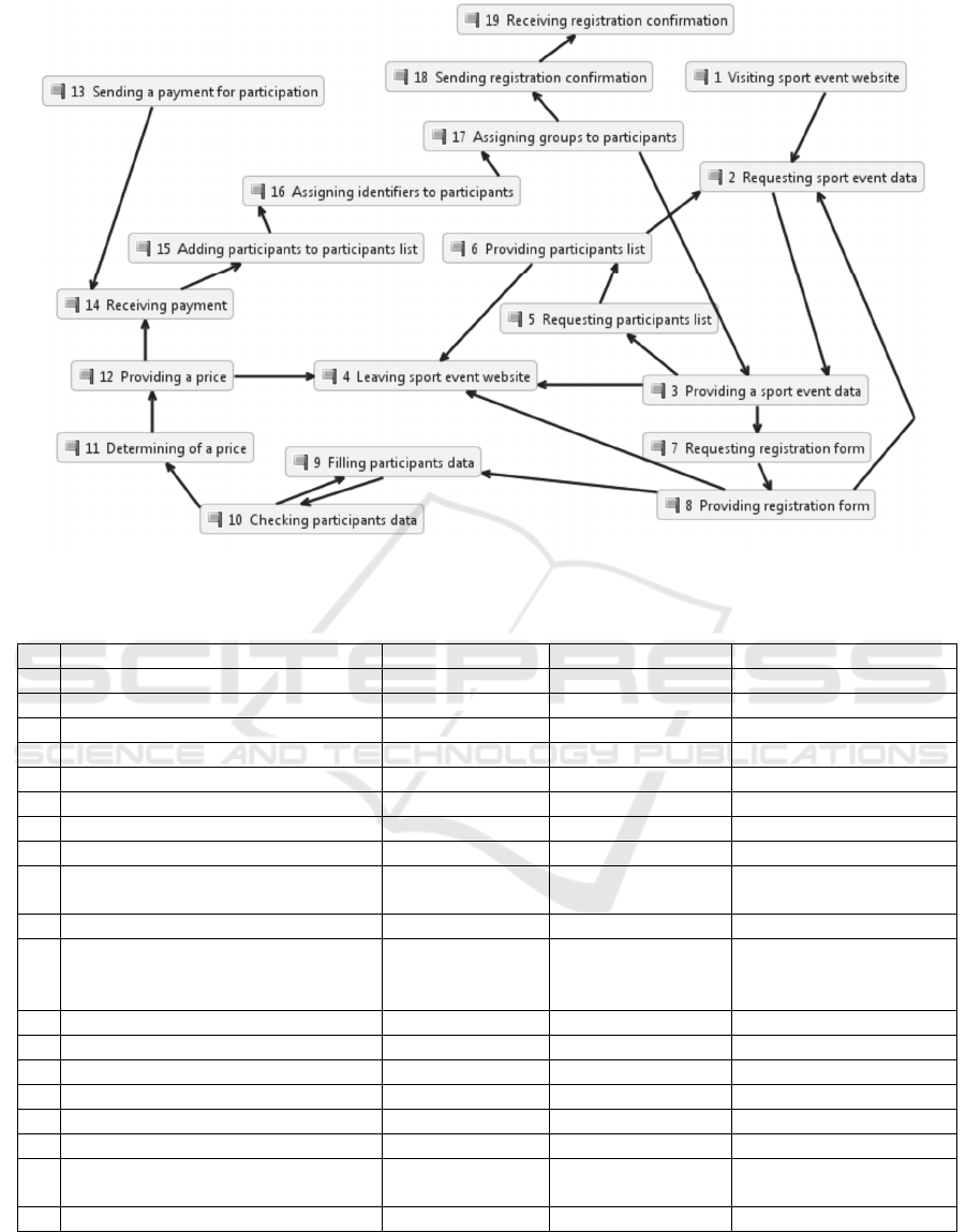
Figure 2: TFM of the problem domain (borrowed from (Ovchinnikova & Nazaruka, 2016)).
Table 2: Functional features of the problem domain (borrowed from (Ovchinnikova & Nazaruka, 2016)).
Id Name Result Executer Precondition
1 Visiting sport event website Visitor
2 Requesting sport event data Visitor
3 Providing a sport event data Sport event data Sport event website
4 Leaving sport event website Visitor
5 Requesting participants list Visitor
6 Providing participants list Participants list Sport event website
7 Requesting registration form Visitor
8 Providing registration form Registration form Sport event website
9 Filling participants data Participant data Visitor
(If registration is
available)
10 Checking participants data Sport event website
11 Determining of a price Price Sport event website
(All mandatory fields are
filled)
(Entered data are correct)
12 Providing a price Sport event website
13 Sending a payment for participation Payment Visitor
14 Receiving payment Sport event website
15 Adding participants to participants list Sport event website (If payment is received)
16 Assigning identifiers to participants Participant id Sport event website
17 Assigning groups to participants Participant group Sport event website
18 Sending registration confirmation
Registration
confirmation
Sport event website
19 Receiving registration confirmation Participant
Lessons Learned on using Execution Model Implementation in Sparx Enterprise Architect for Verification of the Topological Functioning
Model
361
3.2.2 TFM to UML Activity Diagram
Functional features are related with each other by
cause-and-effect relationships. Between cause-and-
effect relationships there can be logical relationships
(Donins, 2012).
Mappings between TFM and UML activity
diagram elements are provided by (Donins, 2012):
- Action from TFM is used as an action in UML
activity diagram;
- Cause-and-effect relationship (TFM) - as an
edge (UML);
- Preconditions (TFM) - guards on edges
outgoing from the decision node (UML);
- Logical relationship (TFM) - as merge,
decision, join or fork nodes or their
combination (UML);
- Input and output (TFM functional features) -
as final and initial nodes (UML) accordingly.
In our case the TFM of the problem domain is
transformed to an activity diagram. It is not divided
into several activity diagrams. That is why it is
necessary to determine the initial node (main entry),
final node (main exit) in the activity diagram.
Optionally end of flows can also be determined.
3.2.3 Execution of UML Activity by
Enterprise Architect
For simulation and possible execution of the UML
activity diagram authors selected the tool Enterprise
Architect version 13.0. User guide for this version is
available in (SparxSystem, 2016).
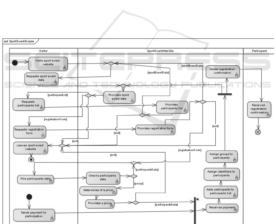
The obtained UML activity diagram from the
TFM during manual transformation by mappings
rules is exported from the Cameo Simulation Toolkit
(see results in (Ovchinnikova & Nazaruka, 2016))
and imported into Enterprise Architect. All elements
of activity diagram were imported as actions (see
Figure 3). Figure 4 represents the console output,
while Figure 5 and Figure 6 show currently active
parts of the simulation and the possible choices of
next steps.
Figure 3: The imported UML activity diagram in Enterprise Architect.
MDI4SE 2017 - Special Session on Model-Driven Innovations for Software Engineering
362
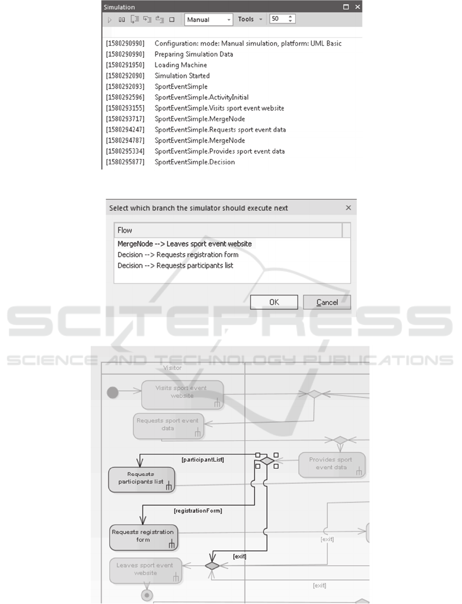
Figure 4: The console output during simulation.
Figure 5: The choice of next step.
Figure 6: The part of the simulation during choice of next step.
Lessons Learned on using Execution Model Implementation in Sparx Enterprise Architect for Verification of the Topological Functioning
Model
363

The authors were not able to find how to add
behavior written in JavaScript to the activity
diagram for action or for activity. Authors of
Enterprise Architect state that for state machines and
activity graphs are enabled JavaScript. The
difference between action and activity is (OMG,
2015a):
- The activity specifies sequence of behavior
and can consists of actions.
- The action is a step within the activity.
The documentation of Enterprise Architect states
that it is possible to do automatic simulation by
providing more suitable next step in decision nodes.
It can be used, when diagram is not complex, yet
with a large number of paths it is hard to trace all of
them visually – manual analysis of information in
the console must be done in this situation.
Alternatively, an automatic check could be done to
make sure that all paths are traced.
Authors found it is difficult to follow the
simulation visually in the Enterprise Architect tool
when only the current action is shown and passed
actions are not indicated. The usage of simulation
capabilities of the program is hardly understandable
for person with basic modeling experience. The user
manual also does not provide any tutorials or
examples for execution models.
3.2.4 Comparison Results
The authors found Cameo Simulation Toolkit to
have a more user-friendly interface and to be more
understandable for persons with basic modeling
experience than Enterprise Architect. In Cameo
Simulation Toolkit, it is possible to choose the
scripting language (e.g. JavaScript, Groovy, Ruby,
Python and BeanShell) in which the user can
provide behavior (e.g. print some information to the
console). In Enterprise Architect is possible to use
only one scripting language – JavaScript. The
authors were not able to find in the tool how to
provide simple outputs to the console (in the form of
behavior), using JavaScript.
The simulation process is visually traceable in
Cameo Simulation Toolkit, because it shows the
current location of execution and passed actions with
different colors. Enterprise Architect shown only
currently executed action while graying out other
parts of the model.
Cameo Simulation Toolkit gives possibility to
use instances with defined values for objects and
these instances can be traced during execution and
simulation of the model. In Enterprise Architect this
feature is not available. In both tools it is possible to
use inside activity diagrams, which describe inside
behavior of an activity.
While both tools do provide the basic
functionality needed for execution models it is not
enough to fully adopt it in practice. Still code needs
to be written and very little code is generated
automatically. The model execution itself is
functional, but it is hard to measure if it provides
extra benefits and does not consume additional time
resources as it is very basic in both tools and will
need additional investments to make it useful. The
documentation for both tools should also feature
more concrete examples and tutorials in order to
more easily adopt the execution model for real
software projects.
The authors also encountered some problems
with Enterprise Architect – the execution sometimes
would loop in the inside activity diagram and not
continue execution, while the same model in Cameo
Simulation Toolkit executed without any problems.
4 DISCUSSIONS AND
CONCLUSION
The implementations of the execution model are still
in their early stages. The analyzed tools cannot
completely cover the execution process and require
further improvements. The practical testing of
execution model capabilities of Enterprise Architect
and Cameo Simulation Toolkit has shown that not
all capabilities described in documentation of the
tools is ready for practical use in the software
development process.
The main goal of all these tools is to provide
modeled system behavior and automatically generate
source code from this model without any coding.
The later part of the goal is not yet realized, because
all of the tools reviewed use programming languages
for providing the execution of system behavior and
actions: Cameo Simulation Toolkit and Papyrus with
Moka use Alf language, Enterprise Architect uses
JavaScript and BridgePoint uses OAL language.
The research hypothesis stated at the beginning
needs to be checked by using the tools Papyrus with
Moka and BridgePoint for case studies. At present,
the obtained results of Papyrus with Moka and
BridgePoint are only documentation-based.
Currently the hypothesis is checked on commercial
tools Cameo Simulation Toolkit and Enterprise
Architect and is partially true. It is partially true,
because some information can be lost during manual
transformation from TFM to the UML activity
MDI4SE 2017 - Special Session on Model-Driven Innovations for Software Engineering
364

diagram. It is planned to automate transformation or
provide synchronization between TFM and activity
diagram. It is time-consuming process to write
scripts for providing behavior and create it inside of
the activity diagram for activity to be executed. It is
planned to analyze in the future work if it is
necessary to store object characteristics (attributes)
in TFM. By comparing TFM and the UML activity
diagram it is possible to see that TFM has a lower
count of elements in graph than UML activity
diagram (join, fork, merge and decision). A large
count of elements can complicate the reading of the
graph, model or diagram.
Theoretically, execution models can help to
determine the weak places in the software system
during model execution and to fix them, yet it is still
not clearly proven in practice. The early error
correction can save time and money in the future,
yet it is necessary to weight in the additional efforts
needed to create and maintain such execution
models. Templates of the user interface (in Cameo
Simulation Toolkit or Enterprise Architect) can be
demonstrated to the customer before the
implementation to help them properly specify their
needs and wishes, which is not a trivial task in most
cases (Chunka, 2011).
Further verification of the results requires the
detailed analysis in action of two additional tools –
Papyrus with Moka and BridgePoint. This will allow
to gain a deeper insight in the benefits these tools
provide as well as their usability in various
situations in conjunction with the TFM.
REFERENCES
Asnina, E. & Osis, J., 2010. Computation Independent
Models: Bridging Problem and Solution Domains. In
Proceedings of the 2nd InternationalWorkshop on
Model-Driven Architecture and Modeling Theory-
Driven Development (MDA & MTDD 2010), in
conjunction with ENASE 2010. Lisbon: SciTePress.
pp.23-32.
Asnina, E. & Osis, J., 2011. Topological Functioning
Model as a CIM-Business Model. In Model-Driven
Domain Analysis and Software Development:
Architectures and Functions. Hershey - New York: IGI
Global. pp.40 - 64.
Atlassian, 2017. The Agile Coach. [Online] Available at:
https://www.atlassian.com/agile/ [Accessed 3
February 2017].
Bentahar, J., Yahyaoui, H., Kova, M. & Maamar, Z.,
2013. Symbolic model checking composite Web
services using operational and control behaviors.
Expert Systems with Applications, 40(2), pp.pp. 508-
522.
Cabot, J., 2017. List of Executable UML tools. [Online]
Available at: http://modeling-languages.com/list-of-
executable-uml-tools/ [Accessed 19 February 2017].
Chunka, M., 2011. Five Dangerous Lessons to Learn From
Steve Jobs. [Online] Available at:
http://www.forbes.com/sites/chunkamui/2011/10/17/fi
ve-dangerous-lessons-to-learn-from-steve-
jobs/#3df415f560da [Accessed 7 February 2016].
Donini, F.M., Mongiello, M., Ruta, M. & Totaro, R.,
2006. A Model Checking-based Method for Verifying
Web Application Design. Electronic Notes in
Theoretical Computer Science, 151(2), pp.19-32.
Donins, U., 2012. Topological Unified Modeling
Language: Development and Application. PhD Thesis.
Riga: RTU.
Donins, U. et al., 2011. Towards the Refinement of
Topological Class Diagram as a Platform Independent
Model. In Proceedings of the 3rd International
Workshop on Model-Driven Architecture and
Modeling-Driven Software Development (MDA &
MDSD 2011). Lisbon: SciTePress. pp.79-88.
Fernandez Cespedes, K., Osis, J. & Alksnis, G., 2015.
Learned by using the Integrated Domain Modeling
Toolset. In Proceedings of 10th International
Conference on Evaluation of Novel Approaches to
Software Engineering. Barcelona, 2015. SciTePress.
Hamilton, C., 2014. Eclipse, NetBeans or IntelliJ: Which
is the best Java IDE? [Online] Available at:
https://jaxenter.com/eclipse-netbeans-or-intellij-
which-is-the-best-java-ide-107980.html [Accessed 7
February 2017].
Konur, S., Fisher, M. & Schewe, S., 2013. Combined
model checking for temporal, probabilistic, and real-
time logics. Theoretical Computer Science, 503,
pp.61-88.
Legay, A., Delahaye, B. & Bensalem, S., 2010. Statistical
Model Checking: An Overview. In First International
Conference, RV 2010. Julian, 2010. Springer Berlin
Heidelberg.
Micskei, Z. et al., 2014. On Open Source Tools for
Behavioral Modeling and Analysis with fUML and
Alf. In 1st Workshop on Open Source Software for
Model Driven Engineering. Valencia, 2014.
Milewicz, R. & Pirkelbauer, P., 2017. Refinement of
structural heuristics for model checking of concurrent
programs through data mining. Computer Languages,
Systems & Structures, 47, pp.170-88.
NoMagic, 2017. Cameo Simulation Toolkit. [Online]
Available at:
http://www.nomagic.com/products/magicdraw-
addons/cameo-simulation-toolkit.html [Accessed 10
February 2017].
OMG, 2015a. OMG Unified Modeling Language. Version
2.4.1. [Online] Available at: http://www.omg.org/spec/
UML/2.4.1/ [Accessed 30 November 2015].
OMG, 2016. Documents Associated With Semantics Of A
Foundational Subset For Executable UML Models.
[Online] Available at: http://www.omg.org/spec/FUM
L/1.1/ [Accessed 10 February 2017].
Lessons Learned on using Execution Model Implementation in Sparx Enterprise Architect for Verification of the Topological Functioning
Model
365

Osis, J. & Asnina, E., 2015. Is Modeling a Treatment for
the Weakness of Software Engineering? In Handbook
of Research on Innovations in Systems and Software
Engineering. Hershey: IGI Global. pp.411-27.
Osis, J. & Donins, U., 2010. Formalization of the UML
Class Diagrams. In Evaluation of Novel Approaches
to Software Engineering. Berlin, 2010. Springer-
Verlag.
Osis, J. & Slihte, A., 2010. Transforming Textual Use
Cases to a Computation Independent Model. In Osis,
J. & Nikiforova, O., eds. Model-Driven Architecture
and Modeling Theory-Driven Development :
Proceedings of the 2nd International Workshop (MDA
& MTDD 2010). Lisbon, 2010. SciTePress.
Osis, J. & Solomencevs, A., 2016. Comparison of
Topological Functioning Model for Software
Engineering with BPMN Approach in the Context of
Model Driven Architecture. In Proceedings of the 11th
International Conference on Evaluation of Novel
Approaches to Software Engineering. Rome, 2016.
SciTePress.
Ovchinnikova, V. & Nazaruka, E., 2016. The Validation
Possibility of Topological Functioning Model using
the Cameo Simulation Toolkit. In 11th International
Conference on Evaluation of Novel Approaches to
Software Engineering (ENASE 2016). Rome, 2016.
SciTePress.
Rivet, C., Cuccuru, A., Marques, B. & Tatibouet, J., 2014.
Papyrus/UserGuide/ModelExecution. [Online] Availa
ble at: https://wiki.eclipse.org/Papyrus/UserGuide/Mo
delExecution [Accessed 7 February 2017].
Seidewitz, E. & Tatibouet, J., 2015. Tool Paper:
Combining Alf and UML in Modeling Tools – An
Example with Papyrus –. [Online] Available at:
https://ocl2015.lri.fr/OCL_2015_paper_1111_1530.pd
f [Accessed 19 February 2017].
Slihte, A., 2015. The integrated domain modeling: an
approach & toolset for acquiring a topological
functioning model. PhD Thesis. Riga: RTU.
Slihte, A., Osis, J. & Donins, U., 2011. Knowledge
Integration for Domain Modeling. In Osis, J. &
Nikiforova, O., eds. Proceedings of the 3rd
International Workshop on Model-Driven Architecture
and Modeling-Driven Software Development (MDA
& MDSD 2011). Lisbon, 2011. SciTePress.
Solomencevs, A., 2016. Topological Functioning Model
for Software Development within MDA (Survey). In
Proceedings of the 11th International Conference on
Evaluation of Novel Approaches to Software
Engineering. Rome, 2016. SciTePress.
Solomencevs, A. & Osis, J., 2015. The Algorithm for
Getting a UML Class Diagram from Topological
Functioning Model. In Proceedings of 10th
International Conference on Evaluation of Novel
Approaches to Software Engineering. Barcelona,
2015. SciTePress.
SparxSystem, 2016. Introduction to Enterprise Architect.
[Online] Available at: http://www.sparxsystems.com/e
nterprise_architect_user_guide/13.0/index/index.html
[Accessed 10 February 2017].
SparxSystems, 2017. Ultimate Modeling Power. [Online]
Available at: http://www.sparxsystems.com/
[Accessed 7 February 2017].
xtUML, 2012. Executable and Translatable UML
Summary. [Online] Available at: https://xtuml.org/wp-
content/uploads/2012/09/xtUML_Summary.pdf
[Accessed 17 January 2017].
xtUML, 2017. eXecutable Translatable UML with
BridgePoint. [Online] Available at: https://xtuml.org/
[Accessed 7 February 2017].
MDI4SE 2017 - Special Session on Model-Driven Innovations for Software Engineering
366
