
Model-driven Development of User Interfaces for IoT Systems
via Domain-specific Components and Patterns
Marco Brambilla and Eric Umuhoza
Dipartimento di Elettronica, Informazione e Bioingegneria,
Politecnico di Milano, Via Ponzio 34/5 20133, Milan, Italy
Keywords:
Internet of Things, IoT, Model-driven Development, User Interaction, Design Patterns, Mobile Applications
Modeling, User Experience, Software Engineering, IFML.
Abstract:
Internet of Things technologies and applications are evolving and continuously gaining traction in all fields
and environments, including homes, cities, services, industry and commercial enterprises. However, still
many problems need to be addressed. For instance, the IoT vision is mainly focused on the technological and
infrastructure aspect, and on the management and analysis of the huge amount of generated data, while so
far the development of front-end and user interfaces for IoT has not played a relevant role in research. On
the contrary, user interfaces in the IoT ecosystem they can play a key role in the acceptance of solutions by
final adopters. In this paper we present a model-driven approach to the design of IoT interfaces, by defining
a specific visual design language and design patterns for IoT applications, and we show them at work. The
language we propose is defined as an extension of the OMG standard language called IFML.
1 INTRODUCTION
User interaction plays a crucial role in a large class of
software and systems. This is true also for the Internet
of Things (IoT) systems, although this aspect has been
frequently neglected. Indeed, the current IoT vision
is mainly focused on the technological and infrastruc-
ture aspect, and on the management and analysis of
the huge amount of generated data, while so far the
development of front-end and user interfaces for IoT
has not played a relevant role in research. On the con-
trary, user interfaces in the IoT ecosystem they can
play a key role in the acceptance of solutions by final
adopters.
The intelligent things connected together by the
IoT paradigm can cooperate and exchange informa-
tion, but their ultimate goal is to provide value to peo-
ple. Such value can be perceived only through ap-
propriate user interfaces, which visualize information
(through dashboard, reports, or infographics), let user
navigate the information, and also interact with the
devices, by setting properties or regulating their be-
havior.
In this paper we propose a model-driven approach
to the design of IoT user interfaces, by defining spe-
cific components and design patterns. Our solution
is based on extending the standard Interaction Flow
Modeling Language (IFML) (Brambilla et al., 2014a)
adopted by the Object Management Group (OMG).
The proposed extensions have been defined through
the following phases: (1) Study of the IoT adoption
and its current applications; (2) Extraction of com-
mon use cases of the IoT, including device manage-
ment, device discovery, interaction with devices, and
information collection from devices; (3) Definition of
a set of new IFML components allowing the model-
ing of the IoT user interactions; and (4) Definition of
a set of reusable design patterns.
The remaining of this paper is organized as fol-
lows: Section 2 reviews the related work; Section 3
discussed the background on IoT and the IFML lan-
guage; Section 4 presents our extensions to IFML
tailored to IoT-based applications development, and
introduces a set of design patterns for the modeling
of the user interactions with IoT systems; Section 5
shows a running example; Section 6 describes the cur-
rent implementation; and Section 7 concludes.
2 RELATED WORK
This work is related to a large corpus of researches
that apply model-driven development (MDD) to spec-
ify the user interaction for multi-device UI mod-
246
Brambilla, M. and Umuhoza, E.
Model-driven Development of User Interfaces for IoT Systems via Domain-specific Components and Patterns.
DOI: 10.5220/0006278302460253
In Proceedings of the 19th International Conference on Enterprise Information Systems (ICEIS 2017) - Volume 2, pages 246-253
ISBN: 978-989-758-248-6
Copyright © 2017 by SCITEPRESS – Science and Technology Publications, Lda. All rights reserved

eling. Among them we can cite: UsiXML (Van-
derdonckt, 2005), TERESA (Berti et al., 2004),
IFML (Brambilla et al., 2014a), and MARIA (Patern
`
o
et al., 2009).
On the other side, the approaches that apply
MDD to the development of IoT-based applications
do not specifically focus on user interfaces and can be
grouped into two clusters. The first cluster includes
the works that target executability for IoT, i.e., pro-
duce executable code for the IoT-based applications.
Among them we can cite: (i) FRASAD (Framework
for sensor application development) (Nguyen et al.,
2015), a node-centric, multi-layered software archi-
tecture which aims at filling the gap between applica-
tions and low-level systems of sensor nodes. It pro-
vides a rule-based programming model which allows
to describe the local behaviors of the sensor node and
a domain specific language for sensor-based applica-
tions modeling. The final application code is automat-
ically generated from the initial models; (ii) Pankesh
Patel and Damien Cassou (Patel and Cassou, 2015)
proposed a development methodology which con-
sists on separating the IoT application development
into different concerns: domain, functional, deploy-
ment, and platform. This separation allows stake-
holders to deal with those concerns individually and
reuse them. The framework integrates a set of mod-
eling languages to specify each of which allowing
to describe one of the above mentioned concerns of
the IoT applications; (iii) Jon Whittle et al. (Fleurey
et al., 2011) proposed a MDD approach to gener-
ate efficient communication APIs to exchange mes-
sages with and between resource-constrained devices.
This approach is based on ThingML (things mod-
eling language) (Franck Fleurey and Brice Morin ,
2016); (iv) Ferry Pramudianto et al. (Pramudianto
et al., 2013) proposed a MDD approach which fo-
cuses on the separation of domain modeling from
technological implementations. The framework al-
lows domain experts to construct domain models by
composing virtual objects and linking them to the im-
plementation technologies. It allows automatic gen-
eration of a prototype code from the domain models
and manual refinement of it.
In the other cluster we include works that apply
MDD to other aspects of IoT applications. Among
them we can mention a MDD approach for the analy-
sis of IoT applications via simulation (Brumbulli and
Gaudin, 2016). Prehofer and Chiarabini (Prehofer
and Chiarabini, 2015) compared the model-based and
mashup approaches, considering tools and method-
ologies for the development of IoT applications. They
used UML and Paraimpu (Pintus et al., 2012).
3 BACKGROUND
3.1 IoT Concepts
This section summarizes the main concepts that char-
acterize an IoT system.
• Device or Thing. It denotes all types of devices
which can generate information (about physical
event or state) and initiate, modify, or maintain
those events or states; or that can perform actions.
• Category. The IoT devices can be grouped into
different categories based on some criterion such
as type, features, and geographical location.
• Terminal. A terminal is any device which can
run an IoT application with a user interface which
can control other devices through the network. A
terminal gathers information from other devices
or external systems and presents it to the user
through the appropriate user interfaces.
• External System. With external system we refer to
all the systems connected to a network in which
the information of devices and terminals can be
stored, processed and retrieved.
• Communication. The devices can communicate
in different ways and can be connected with ter-
minals and external systems. Several communi-
cation protocols for the IoT have been proposed
around the IEEE 802.15.X, a standard for lower
power systems.
• Intermediary. It represents any device or system
which acts as a gateway between the IoT device
and the terminal in an indirect communication.
3.2 UI Modeling
To describe how the users interact (using terminals)
with IoT devices, we use a OMG standard for user
interaction modeling: the Interaction Flow Modeling
Language (IFML) (Brambilla and Fraternali, 2014).
IFML can be extended for specific needs or domains.
For instance, the work in (Brambilla et al., 2014b)
and (Umuhoza et al., 2015) proposed an extension
of IFML for mobile applications.The most important
core elements of IFML are:
• ViewElements. View elements are the elements
of the user interface that display the content of
the application. They are further divided into:
ViewContainers, the elements of the user inter-
face which aggregate other containers and com-
ponents; and ViewComponents, elementary pieces
of information constituting the interface.
Model-driven Development of User Interfaces for IoT Systems via Domain-specific Components and Patterns
247
• Events. Event is the concept that represents the
events that may affect the state of the user inter-
face. The events can be produced by the user’s
interactions, application, or an external system.
• Interaction Flow. The effect of an event is rep-
resented by an interaction flow connection, which
connects the event to the view container or com-
ponent affected by the event.
• Actions. The actions are placeholders for business
logic, used to express the side-effects of the user’s
interaction.
4 MODELING LANGUAGE AND
DESIGN PATTERNS FOR IOT
In this section, we present the IFML extensions for
the modeling of the IoT-based applications and the
design patterns for these applications.
4.1 Modeling Language for IoT
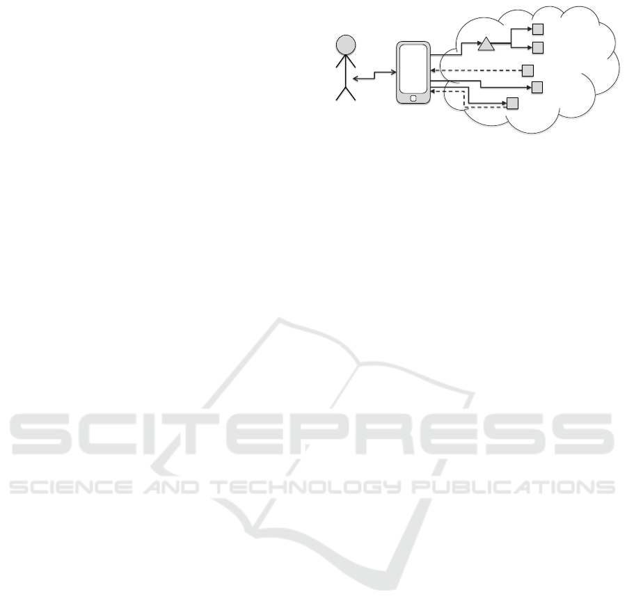
The interactions between the user and the IoT sys-
tems, as shown in Figure 1, can be logically divided
in two phases:
1. User Terminal communication. This phase
represents the interactions between the user and
the terminal used to access the IoT system.
2. Terminal IoT devices communication. This
phase represents the interactions between the ter-
minal and the IoT devices.
The first phase of the user interaction with IoT
systems can be modeled using the IFML standard
and its current extensions, especially the Mobile
IFML (Brambilla et al., 2014b). This section treats
the second part of the interactions with the IoT sys-
tem: TerminalIoT devices interactions. It presents
the new elements added to the IFML to model both
the events and actions associated to the IoT devices.
4.1.1 IoT Events
In this section we describe the new events defined as
IFML extension for the IoT domain. Those events are
grouped in: events from devices, and events associ-
ated to IoT actions.
Events from Device. The IoT devices emit specific
signals containing information about their status or
about what they are monitoring. Those signals are
captured by specific catching events and sent to the
users (terminal) in form of notifications. Those events
are grouped into two categories:
Terminal
User
IoT Device
Intermediary
IoT Device
IoT Device
IoT Device
IoT System
Command
Request
ResponseData
IoT Device
PushedData
Figure 1: Overview of the user interaction with the IoT
Systems through the terminal, consisting in sending com-
mands and requesting or monitoring data from the IoT de-
vices (possibly through an intermediary).
1. Single Information Event. It is an event which
captures every single message from the device it is
listening to. A new class SingleInformationEvent
extending SystemEvent of the IFML standard has
been defined to model the events which capture
every single message sent by a specific device.
The usage of this event is described in Figure 2.
2. Approaching Event. It is an event that allows the
capturing of a first signal sent by each device it is
listening to. The approaching event is used when
the information transmitted by each device must
be shown to the user only once: each time the
device is detected for the first time by the ter-
minal or when the device went out of the cover-
age range and comes back in. A new class, Ap-
proachingEvent, extending SystemEvent has been
defined to model the approaching events. The
model depicted in Figure 3 exemplifies the usage
of approaching event.
Action Events. This category regroups two types of
events:Timer event. It represents the time on which
the associated action is scheduled for execution; and
Repeat event. It specifies the time on which the exe-
cution of associated action will be repeated. We have
defined a new class for each type of those events:
TimerEvent and RepeatEvent.
4.1.2 IoT Actions
This category contains the components that allow to
model the actions triggered when the user interacts
with different IoT devices. Those actions can be
grouped in two categories: Device actions, that rep-
resent the actions sent directly to the devices; and In-
termediary actions, that represent the actions sent to
the devices through an Intermediary. Each category
can be further decomposed into two subcategories:
Set and Get actions.
ICEIS 2017 - 19th International Conference on Enterprise Information Systems
248
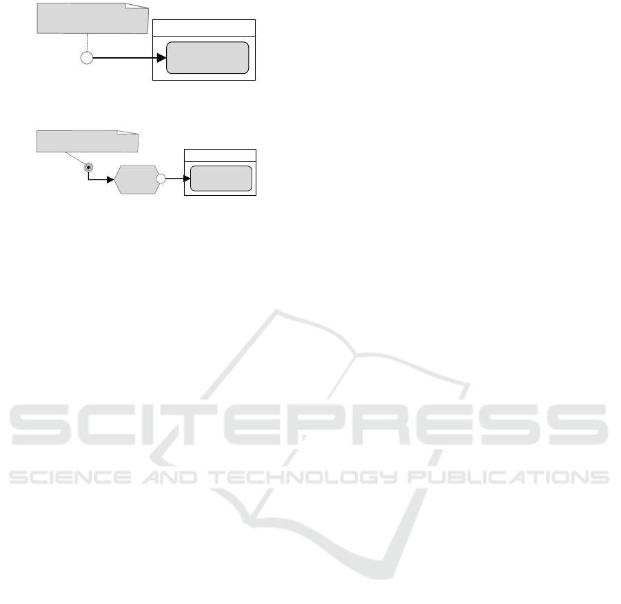
SingleInformationEvent
Notification
«Details»
Information
«ActivationExpression»
Context. ConnectivityType <> “NONE”
Figure 2: Example of usage of SingleInformationEvent. A
notification is shown to the user when the event is activated.
Notification
«Details»
Information
ApproachingEvent
«ActivationExpression»
Context. ConnectivityType = “BLUETOOTH”
Get Details
(device)
Figure 3: Example of usage of ApproachingEvent. The de-
tails of a device are displayed to user as notification once he
enters into the coverage area of that device.
Set Actions. This category contains the actions that
allow the user to send to one or more devices, a set of
identifiers of the operations or programs which those
devices have to perform or execute. We assume that
the operations are known a priori by the devices, thus
when we send an identifier of an operation to a given
device, the device knows how to perform the corre-
sponding operation. The Set operations are mainly
used to configure the devices (e.g.: change the range
in which the sensors are activated) and to perform spe-
cific actions such as turn on and turn off the device.
Get Actions. The Get actions are used to retrieve
the information from devices, category of devices, or
an operation. We have defined a new class, Get, that
allows to model those actions. The class Get has been
further extended to represent the specific data to re-
trieve. Examples of those data include details of the
device, information provided by the device, and status
of the operation assigned to the device.
Plan Action. For the previous actions, we assume
that the devices execute specified operations once the
user triggers the action. But there exist other cases
in which the user wants to schedule the execution of
a given action at a specific time. We have defined a
specific action, called Plan, to model those operations
which are not executed immediately by the devices
but scheduled for execution (once or several times) in
a subsequent moment. Plan is an asynchronous action
that waits until the time scheduled for the execution of
the operation. It inputs the targeted devices, execution
time, operations, and optionally (for the repeating ac-
tions or operations) the number of repetitions.
4.2 Interaction Design Patterns
This section presents the IoT interactions under a
problem-oriented view, and thus complements the
component-oriented perspective of the preceding sec-
tion. It introduces a number of design patterns that
can be used to tackle typical problems in the design
of the user interactions with the aim of showing the
expressiveness of the designed IoT extensions. We
group those patterns in two categories:
1. Set Patterns. This category regroups patterns that
allow the user to send to the devices operations or
programs to be executed (see Table 1); and
2. Get Patterns, which contains the interaction pat-
terns that allow to retrieve information from a de-
vice, category, program or an operation (Table 2).
5 CASE STUDY
To demonstrate the effectiveness of the designed ex-
tensions and the usage of UI design patterns pre-
sented in Section 4, we have modeled the interaction
of smart-home, an application that allows a user to in-
teract with different devices of a smart home system.
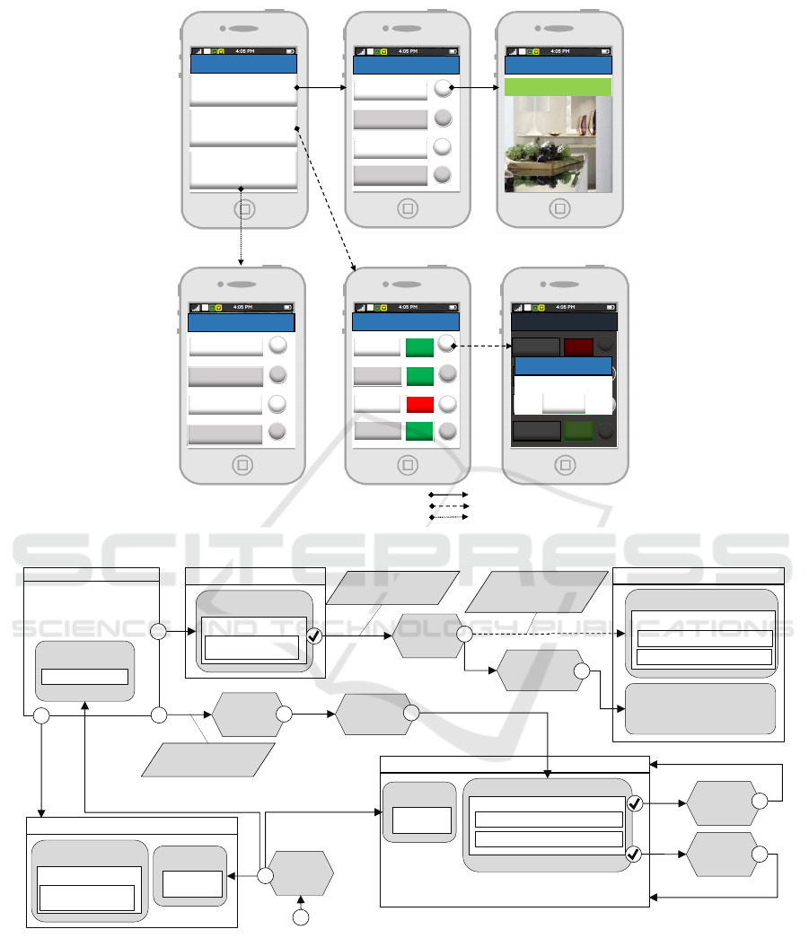
Figure 4 contains a piece of the user interface
of smart-home application. The UI in Figure 4 is
divided in three paths:(i) Manage cameras. When the
user selects manage camera from the Home screen,
a new screen Cameras showing a list of available
cameras is displayed. The button Details associated
to each camera allows the user to access to the de-
tails, state and current image, of the selected camera;
(ii) Manage Lights. Once the user selects Manage
Lights from the Home screen, a new screen called
Lights is displayed. The screen Lights, contains a
list of available lights with their current state (ON or
OFF). The user can change the state of the selected
light by pressing on/of button associated to each
light; (iii) Manage Alarms. The path which allows
the user to see the logs of recent alarms. Once the
user selects manage alarm from the home screen, a
new screen Recent Alarms containing a list of the
recent alarms is displayed. Figure 5 shows the IFML
model describing the user interaction of the piece
of smart-home application presented in Figure 4.
The interaction model is obtained by combining the
following IoT user interaction patterns:
• Get Information from whole Category, used to re-
trieve the current status (on/off) of the monitored
lights;
• Get State of the Device, used to retrieve the cur-
rent state of Camera01;
Model-driven Development of User Interfaces for IoT Systems via Domain-specific Components and Patterns
249
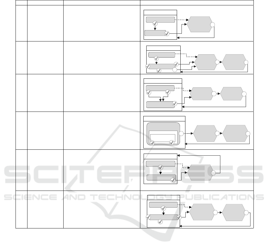
Table 1: IoT User Interaction Patterns: Set Patterns.
ID Pattern Description Example
P1 One Device
One Operation
This pattern allows the user to set an op-
eration to be executed by one specific
device. The user selects a device of in-
terest from a list of the devices of the
system. Then, he chooses the operation
to be performed from a list of operations
supported by the selected device.
App
«List» Devices
[Device]
Set (device,
operation)
Select device
«List» Operations
Select
Operation
P2 One Device
More Operations
This pattern allows the user to send to
a single device a set of the operations
to be performed. The interactions start
with the selection of a device of interest.
Then the user selects desired operations
from a list of supported operations.
App
«List» Devices
«MultiChoice» Operations
Plan (device,
operationList)
Set Operations
Select
device
Select
Operation
Check
Uncheck
[Device]
Set (device,
operation)
P3 More Devices
One Operation
This pattern allows the user to send to
many devices one operation to be exe-
cuted. The interactions start by select-
ing the devices of interest. Then the user
selects an operation (from a list of the
operations supported by the selected de-
vices) to be executed by those devices.
App
«MultiChoice» Devices
[Device]
Set (device,
operation)
Check
Uncheck
«List» Operations
Select
Operation
Plan
(deviceList,
operation)
P4 More Devices
More Operations
This pattern allows the user to send a set
of operations to different devices. Those
operations are not necessary the same
for all devices, thus the operations must
be binded to the devices which can per-
form them.
App
«MultiChoice» Devices
Set Operation
«DataBinding» Device
«NestedDataBinding»
Operation
Check Uncheck
Plan
(List<device,
operation>)
[Device]
Set (device,
operation)
P5 One Device
One Program
This pattern allows the user to send the
program (identifier) to the device which
will execute it. A program is a set of op-
erations which have to be executed in a
precise order. We assume that the pro-
grams are already configured in the de-
vices, thus, the user has only to send the
program identifier to the device.
App
«List» Devices
[Device]
Set (device,
program)
Select device
«List» Programs
P6 One Category
More Operations
This pattern allows the user to set oper-
ations to different devices based on the
groups they belong to, without needing
to select one device at a time.
App
«List» Categories
«MultiChoice» Operations
Set (category,
operationList)
Set
Operations
Select device
Check
Uncheck
[Device]
Set (device,
operation)
• Get Information from the Device, used to retrieve
information about the object monitored (image
displayed in the screen Camera 01) by Camera01;
• One Device One Operation, used for instance to
turn off the Light01;
• Get Details of a Device, used to access the details
of the selected logLine of the alarms. The details
of the IoT devices can be also retrieved from the
repository of the system;
• Store Information, used to store the new alarm;
• Push Information, used to inform the user about
the new alarm. In the showed case, the new alarm
was arrived, as a notification message, while the
user was visualizing the updated list of Lights af-
ter turning off Light01.
6 IMPLEMENTATION
Besides the formal definition of the IoT extensions to
the IFML language and the modeling of UI design
patterns for IoT, our research included the implemen-
tation of the approach in terms of a model editor and
a code generator prototype tailored to IoT applica-
tions development. For the implementation we relied
on WebRatio, a development environment supporting
IFML that comprises several modeling perspectives
and includes a code generation framework that auto-
mates the production of the software components in
all the tiers of the application and the connection be-
tween the application and external APIs. Our imple-
mentation work consisted in specifying the IoT com-
ponents as WebRatio components. This allowed the
components to be used in the visual editors in the
ICEIS 2017 - 19th International Conference on Enterprise Information Systems
250
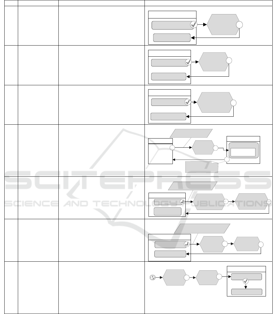
Table 2: IoT User Interaction Patterns: Get Patterns.
ID Pattern Description Example
P7 Get Details of a
Device
The user retrieves the general informa-
tion of a device such as Id, name, de-
scription, and model. The user selects a
device he is interested in from a list of
devices.
App
«List» Devices
[Device]
Get (device)
Select
device
«Details» Device
P8 Get State of the
Device
This pattern allows the user to retrieve
the state a given device. The interac-
tions start with the selection of the de-
vice for which the user needs tho know
the state. Then, the corresponding state
is displayed to the user.
App
«List» Devices
[Device]
Get State
(device)
Select
device
«Details» Device
P9 Get Information
from the Device
This pattern allows the user to retrieve
the information provided by a device
about the monitored object.
App
«List» Devices
[Device]
Get Information
(device)
Select device
«Details» Information
P10 Application
Launch
The information sent by the devices
when the application is not running on
the terminal or when the user is offline
is generally stored in an external system
where the user can retrieve it when he
launches the application or when he is
connected. This pattern allows the user
to retrieve that information at applica-
tion launch or when he becomes online.
Home
Get
Information
(User)
LaunchingEvent
«Modal» Notifications
Close
«ActivationExpression»
isSynchronized()=TRUE
«ParamBindingGroup»
Context.username User
«DataBinding»
Information
«List» Notifications
P11 Search Device This pattern allows the user to search a
specific device. The search of the device
can be done in different ways depending
on the application and on the devices.
App
«List» Devices
Get
devices
[Device]
Get
(searchParameter)
«Form» parameter
«ParamBindingGroup»
parameter searchParameter
Plan
(searchParameter)
P12 Nearby Devices This pattern allows the user to retrieve
all the devices near to a given location.
The location can be setted by the user or
retrieved from the ContextDimension,
Position, which represents the location
information of the device used to access
the application.
App
«List» Devices
Get device
[Device]
Get (device)
«Form» loca tion
Plan
(location)
«ParamBindingGroup»
location location
P13 Pull Information This pattern allows the user to check pe-
riodically availability of new data from
devices. To save some resources like
power, for the data that can be delayed
for some amount of time without im-
pacting on the outcome of the applica-
tion, the user can decide to activate pe-
riodically the listening service and pull
all the information from the devices.
Plan
(deviceList)
App
«List» Devices
«Details» Device
Select
device
Time Event
[Device]
Get
(device)
design phase and to be used as sources in prototype
code generation rules for web and mobile apps (Acer-
bis et al., 2015).
7 CONCLUSIONS
In this paper we presented the IoT extensions of
OMG’s standard IFML for modeling the UI of the
IoT-based applications. We have presented a set of
design patterns for the common user interaction for
Model-driven Development of User Interfaces for IoT Systems via Domain-specific Components and Patterns
251
Manage Lights
Manage Alarms
Manage Cameras
Cameras
Camera 01
Camera 02
Camera 03
Camera 04
Details
Details
Details
Details
Camera 01
State: active
Lights
Light 01 ON
Light 02
Light 03
OFF
Light 04
ON
ON
On/Off
On/Off
On/Off
On/Off
Lights
Light 01
Light 02
Light 03
Light 04
ON
ON
On/Off
On/Off
On/Off
On/Off
OFF
ON
Alarm
Close
2016-10-01:…
Details
Details
Details
Details
Recent Alarms
2016-10-01:…
2016-10-01:…
2016-10-01:…
Path to manage cameras
Path to manage lights
Path to manage alarms
Home
Figure 4: Case study: a piece of user interface of smart-house application.
[H] Manage Devices
Manage
Cameras
Cameras
«List» Cameras
«DataBinding» Camera
«VisualizationAttribute»
name: String
[Device]
Get State
(Camera)
[Device]
Get Information
(Camera)
Camera Details
«Details» Camera Details
«DataBinding» Camera
«VisualizationAttribute» name: String
«System» Current Image
«VisualizationAttribute» State: String
«ParamBindingGroup»
selectedCamera Camera
currentState State
«ParamBindingGroup»
selectedCamera Camera
Manage
Lights
Get
Information
(category)
«ParamBindingGroup»
lightcategory
[Device]
Get
Information
(Light)
Lights
«List» Lights
«DataBinding» Light
«VisualizationAttribute» name: String
«VisualizationAttribute» lightOn: Boolean
Turn On
Turn Off
[Device]
Set (Light,
Turn On)
[Device]
Set (Light,
Turn Off)
Manage
Alarm
Logs of Alarm
«List» Alarms
«DataBinding» Alarm
«VisualizationAttribute»
log: String
New Alarm
Log New
Alarm
«Modal» Alarm
«Message»
Alarm
«Modal» Alarm
«Message» Alarm
Get
Details
«Modal» Alarm
«Message»
Alarm
Figure 5: Example of pattern-based modeling. The user interaction model is obtained by combining various design patterns.
those applications. Besides the formal definition of
the IoT extensions to the IFML language and the
modeling of UI design patterns for IoT, our research
included the implementation a code generator. The
future works include the completion of code genera-
tors and broader coverage of the use cases.
REFERENCES
Acerbis, R., Bongio, A., Brambilla, M., and Butti, S.
(2015). Model-driven development of cross-platform
mobile applications with web ratio and IFML. In 2015
2nd ACM International Conference on Mobile Soft-
ICEIS 2017 - 19th International Conference on Enterprise Information Systems
252

ware Engineering and Systems, MOBILESoft 2015,
Florence, Italy, May 16-17, 2015, pages 170–171.
Berti, S., Correani, F., Mori, G., Patern
`
o, F., and Santoro, C.
(2004). Teresa: a transformation-based environment
for designing and developing multi-device interfaces.
In CHI Extended Abstracts, pages 793–794.
Brambilla, M. and Fraternali, P. (2014). Interaction flow
modeling language: Model-driven UI engineering of
web and mobile apps with IFML. Morgan Kaufmann.
Brambilla, M., Fraternali, P., et al. (2014a). The Interaction
Flow Modeling Language (IFML), version 1.0.
Brambilla, M., Mauri, A., and Umuhoza, E. (2014b).
Extending the Interaction Flow Modeling Language
(IFML) for Model Driven Development of Mobile
Applications Front End. In MobiWIS, pages 176–191.
Brumbulli, M. and Gaudin, E. (2016). Towards model-
driven simulation of the internet of things. In Com-
plex Systems Design & Management Asia, pages 17–
29. Springer.
Fleurey, F., Morin, B., Solberg, A., and Barais, O. (2011).
Mde to manage communications with and between
resource-constrained systems. In MODELS, pages
349–363.
Franck Fleurey and Brice Morin (2016). ThingML.
http://thingml.org. Online; accessed 6 September
2016.
Nguyen, X. T., Tran, H. T., Baraki, H., and Geihs, K.
(2015). Frasad: A framework for model-driven iot
application development. In WF-IoT, pages 387–392.
IEEE.
Patel, P. and Cassou, D. (2015). Enabling high-level appli-
cation development for the internet of things. Journal
of Systems and Software, 103:62–84.
Patern
`
o, F., Santoro, C., and Spano, L. D. (2009). Maria: A
universal, declarative, multiple abstraction-level lan-
guage for service-oriented applications in ubiquitous
environments. ACM Trans. Comput.-Hum. Interact.,
16(4).
Pintus, A., Carboni, D., and Piras, A. (2012). Paraimpu: a
platform for a social web of things. In WWW, pages
401–404. ACM.
Pramudianto, F., Indra, I. R., and Jarke, M. (2013). Model
driven development for internet of things application
prototyping. In SEKE, pages 703–708.
Prehofer, C. and Chiarabini, L. (2015). From internet
of things mashups to model-based development. In
COMPSAC, 2015 IEEE, pages 499–504.
Umuhoza, E., Brambilla, M., Cabot, J., Bongio, A., et al.
(2015). Automatic code generation for cross-platform,
multi-device mobile apps: some reflections from an
industrial experience. In MobileDeLi, pages 37–44.
ACM.
Vanderdonckt, J. (2005). A MDA-compliant environment
for developing user interfaces of information systems.
In CAiSE, pages 16–31.
Model-driven Development of User Interfaces for IoT Systems via Domain-specific Components and Patterns
253
