
High-speed Motion Detection using Event-based Sensing
Jose A. Boluda, Fernando Pardo and Francisco Vegara
Departament d’Inform
`
atica, Escola T
`
ecnica Superior d’Enginyeria, Universitat de Val
`
encia,
Avd. de la Universitat S/N, 46100 Burjassot, Val
`
encia, Spain
{jose.a.boluda, fernando.pardo, francisco.vegara}@uv.es
Keywords:
High-speed Motion Analysis, Event-based Sensing, FPGA System, Laser Triangulation.
Abstract:
Event-based vision emerges as an alternative to conventional full-frame image processing. In event-based sys-
tems there is a vision sensor which delivers visual events asynchronously, typically illumination level changes.
The asynchronous nature of these sensors makes it difficult to process the corresponding data stream. It might
be possible to have few events to process if there are minor changes in the scene, or conversely, to have an
untreatable explosion of events if the whole scene is changing quickly. A Selective Change-Driven (SCD)
sensing system is a special event-based sensor which only delivers, in a synchronous manner and ordered by
the magnitude of its change, those pixels that have changed most since the last time they have been read-out.
To prove this concept, a processing architecture for high-speed motion analysis, based on the processing of the
SCD pixel stream has been developed and implemented into a Field Programmable Gate-Array (FPGA). The
system measures average distances using a laser line projected into moving objects. The acquisition, process-
ing and delivery of distance takes less than 2 µs. To obtain a similar result using a conventional frame-based
camera it would be required a device working at more than 500 Kfps, which is not practical in embedded
and limited-resource systems. The implemented system is small enough to be mounted on an autonomous
platform.
1 INTRODUCTION
The representation of a scene at a time t as a still im-
age is the most common source of data to extract vi-
sual information from.Typical artificial video systems
are based on the sequential acquisition and process-
ing of full-frame images. All the pixels in the image
are acquired and processed, without taking into ac-
count how many changes there have been in the scene.
This fact makes it difficult to reduce the control loop
delay in real-time applications. Instead, nature does
not follow this approach. Biological vision systems
do not follow the policy of capturing and sending se-
quences of full frame images at a fixed rate. Living
beings evolved in a completely different manner. Par-
ticularly, vision in biological systems is based on dif-
ferent kinds of photoreceptors, which asynchronously
respond to light stimuli and send information to up-
per levels of cognitive systems (Gollisch and Meister,
2008). Following these ideas, engineers have tried to
mimic the results of millions of years of evolution to
solve many problems, especially in the field of sens-
ing (Vincent, 2009).
A Selective Change-Driven (SCD) vision sen-
sor only delivers, ordered by the magnitude of their
change, the pixels that have changed most since their
last read-out. Pixels where there is not any illumi-
nation level change are not sent. Consequently, an
SCD sensor only delivers non-redundant information
and no time or energy is wasted sending already sent
information. Moreover, since this information is or-
dered and delivered synchronously according to the
absolute magnitude of its change, the most signifi-
cant changes will be processed first. This pixel pri-
ority policy, based on the magnitude of illumination
change, can be relevant for some real-time applica-
tions which must be accomplished with time restric-
tions, because often it is impossible to process all the
events delivered by the sensor. We think that this pol-
icy could be useful since greater image changes would
be more relevant in any task most of the times.
2 EVENT-BASED SENSORS AND
SYSTEMS
Many biologically inspired sensors are based on the
Address Event Representation (AER) model (Ma-
howald, 1992). In this model, pixels operate individ-
246
Boluda J., Pardo F. and Vegara F.
High-speed Motion Detection using Event-based Sensing.
DOI: 10.5220/0006183902460253
In Proceedings of the 12th International Joint Conference on Computer Vision, Imaging and Computer Graphics Theory and Applications (VISIGRAPP 2017), pages 246-253
ISBN: 978-989-758-225-7
Copyright
c
2017 by SCITEPRESS – Science and Technology Publications, Lda. All rights reserved

ually, without any data request, and fire themselves
according to their illumination level change. Event-
based sensors can be classified accordingly to the way
the light is transformed into an electrical signal: light
integration-based sensors are based on a capacitor that
stores a charge, which is proportional to illumination
intensity and integration time. In this way, sensors de-
signed with integration photoreceptors are less noisy
and offer a good image quality. Instead, these sen-
sors are not very fast, because the integration time de-
grades the fast event-driven response speed. On the
contrary, continuous conversion-based sensors pro-
vide a faster response to image changes. Instead, they
are noisier than the integration-based sensors.
The first SCD sensor, had a 32x32 resolution,
based on an integration photoreceptor, which gave a
time resolution of 500 µs (Zuccarello et al., 2010b).
Instead, the current SCD sensor takes advantage of a
continuous conversion cell, allowing higher working
speeds. Moreover, this last developed SCD sensor has
a resolution of 64x64 (Pardo et al., 2015). This sensor,
as any event-driven sensor, takes advantage of data
reduction, but on the contrary than most event-based
sensors, the SCD sensor has a synchronous interface
which delivers information when the processing sys-
tem requests it. Additionally, the feature of reading-
out events ordered by the magnitude of their change,
allows the implementation of systems that can just
work with some of the scene changes (the most rele-
vant ones). This computing-oriented interface makes
the SCD sensor a good candidate to be easily inte-
grated into an embedded processing system.
Difficulties arise when trying to implement event-
based vision processing on computers. Comput-
ers are sequential in nature, while human brain is a
huge parallel system with roughly 100 billion neu-
rons (Herculano-Houzel, 2009). The key of the hu-
man brain performance is based on the massive quan-
tity of connections and on its ability to parallel func-
tioning. This allows it to deal with the explosion
of events in the visual cortex, which produces a fast
moving object. Computer’s sequential nature can be
overcome with parallel architectures, but the achieved
throughput is not near to the performance achieved in
living-beings vision systems. Trying to mimic neuro-
biological structures, present in the nervous system,
neuromorphic systems (van Schaik et al., 2015) (Liu
et al., 2015) appear as implementations in VLSI cir-
cuits of sensors and neural systems. The architec-
ture of these systems is based on neurobiology, be-
ing AER a particular case of a neuromorphic ap-
proach (Serrano-Gotarredona et al., 2006).
There have already been some examples of neuro-
morphic systems implemented in full-custom chips.
In (Camunas-Mesa et al., 2012) a convolution mod-
ule with 64x64 pixels is presented. It was designed
to allow many of them to be assembled to build mod-
ular and hierarchical Convolutional Neural Networks
(ConvNets). In the same way, some other neuromor-
phic systems use FPGAs as processing elements. For
instance, a fully digital implementation of a spiking
convolutional event-driven core implemented in FP-
GAs has been presented (Yousefzadeh et al., 2015).
This system uses a Dynamic Vision Sensor (DVS), an
FPGA and two USB AER mini boards that send AER
spikes through a USB connection to a computer. Sim-
ilarly, in (Camunas-Mesa et al., 2014) a neuromor-
phic system is implemented mixing the DVS event-
driven sensor chip together with event-driven convo-
lution module arrays implemented in this case on FP-
GAs. Experimental results in this paper are the imple-
mentation of Gabor filters and 3D stereo reconstruc-
tion systems.
AER-based processing systems show good speed
performance, reducing the control loop delay for
some tasks, achieving a minimum delay. Some of
these systems are complex systems with many re-
sources, which means that it could be difficult to use
them in embedded or limited resource systems, due to
power or space limitations. In our view, living beings
neural system should not be mimicked as a goal itself.
The final goal should be to have working systems to
accomplish specific tasks. The asynchronous nature
of AER sensors may difficult the subsequent comput-
ing stages, since there can be a non-balanced rate of
events over time. Frequently, the processing system
would have to deal with too many events, which can
be impossible to process in real-time. In this paper,
we show that in resource-limited systems, such as au-
tonomous robots, etc, event-based systems may have
a traditional synchronous interface. A neuromorphic
approach could need a more resource-heavy and less
feasible system. The approach presented in this pa-
per is a small portable event-based high-speed motion
detection system.
3 HIGH-SPEED SCD SYSTEM
SCD vision can be used as a object-distance detection
system for an autonomous moving system. The sys-
tem should be able to detect objects moving at very
high-speeds with very few resources. The same thing
would be much more difficult to achieve using a tra-
ditional frame-based vision system. In our system, a
stream of changes is necessary, so there must be rel-
ative movement between the camera and the object.
The autonomous vehicle, with the SCD system, must
High-speed Motion Detection using Event-based Sensing
247
be moving with respect to the object, or the obstacle
should move with respect to the vehicle. If there is
relative movement the object can be detected, which
is the interesting case since there could be a collision.
In the case that there is not relative movement be-
tween the vehicle and the obstacle, would the object
not be detected, but it does not matter since there is no
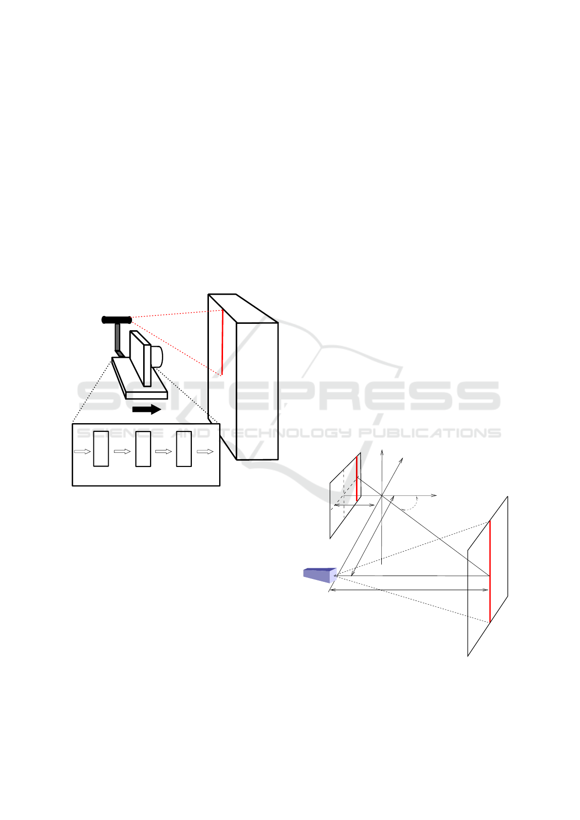
chance of collision. The system idea can be seen in
Figure 1 where the camera-laser system is approach-
ing to an object. Slow speed movements achievable
with an autonomous vehicle will not prove the SCD
advantages, since this detection could be achieved
with a conventional camera. In order to find out the
system limits, instead of a slow moving system, we
have tested the system with a high-speed rotating tool,
which is one of the fastest mechanical devices avail-
able.
SCD
camera
Laser beam
Distance computation FPGA
Column
storage
x average
value
(x, y)
Fixed to
floating
Arithmetic
operations
distance
Obstacle
Figure 1: Motion detection system.
Figure 1 shows the system based on active laser
triangulation. The detection system could be mounted
on a moving vehicle, as an autonomous robot. A laser
projects a line in front of the camera. The laser line is
then captured by the SCD camera, placed at a known
distance from the laser. The position of the laser in
the sensor image gives the distance between the cam-
era and the surface, as it will be explained in section
3.1. The laser image in the sensor plane will change
when the vehicle moves and the distance between the
camera and the laser projection varies. Each distance
gives a different x column in the sensor plane.
We have decided to compute the average distance
of the surface profile, so our architecture will com-
pute the average distance between the camera and the
projected laser. A different column value is obtained
for each row. If the the line is projected onto an ir-
regular surface, the line image would give a different
column for each different distance, providing a depth
map.It would be possible to implement a combinato-
rially look-up table to calculate each pixel distance,
because there are only 64 columns and each column
position is bi-univocally related to a distance, but for
this first prototype we decided to compute the average
distance.
3.1 Laser Triangulation Subsystem
The system uses Active Triangulation for distance
measurement. In (Khoshelham and Elberink, 2012)
and in (Acosta et al., 2006) can be seen some con-
figurations, with different features, which depend on
the pursued goal; accuracy, range, etc. In the case
of our SCD distance detection system, extreme accu-
racy or range is not required, since this is a first hard-
ware demonstrator which tries to validate the SCD
approach. Figure 2 shows a simplified pin-hole rep-
resentation of triangle equivalences shown in these
papers. The basic principle of the method consists
of projecting a laser line onto the surface to be mea-
sured. Subsequently, the image is captured in the sen-
sor plane. It is mostly certain that the laser line will
fall on one column or two, while moving between
columns, because the laser line is narrow, as well as
the pixel size. It must be noted that the sensor has
only 64 columns.
d
Laser
h
f
θ
Sensor plane
Object surface
Figure 2: Simple pin-hole triangulation scheme.
It is possible to construct the following equation
from figure 2:
VISAPP 2017 - International Conference on Computer Vision Theory and Applications
248

h =
d
tan(θ)
(1)
where h is the distance value between the laser-
camera system and the surface being measured and
d is the known laser-camera gap. The angle θ can be
obtained as a function of its displacement in the im-
age plane (in pixels). Moreover, if a linear model is
followed for the angle θ, it can be expressed as:
θ = x · ω + φ (2)
In equation (2) x is the distance in pixels from the
computed pixel to the image centre (pixel column), ω
is a parameter which gives the radians per pixel ratio,
and φ is a parameter for alignment error compensa-
tion. Both parameters must be measured after a cal-
ibration process. Consequently, equation (1) can be
expressed as:
h =
d
tan(x · ω + φ)
(3)
The parameter x is the pixel column value, and
it is obtained from the sensor data stream. The sys-
tem range is adjusted by parameters ω and φ. A
higher polynomial fitting, instead of the linear adjust-
ment performed, would give more accurate values for
the angle θ. As a disadvantage, this higher precision
would give a higher hardware complexity that could
require a bigger FPGA. Moreover, this higher poly-
nomial fitting could produce a higher delay. After the
calibration process, it has been achieved a coefficient
of determination R
2
of 0.9984 with the linear adjust-
ment, so the linear fitting has been accepted as good
enough and no further improvement in this aspect has
been considered.
3.2 SCD Sensor and Camera
The latest SCD sensor has a resolution of 64×64
pixels and it has been designed based on a conver-
sion cell (Pardo et al., 2015). There was a previous
32×32 SCD sensor based on an integration cell (Zuc-
carello et al., 2010a) that already showed its utility
in resource-limited systems (Pardo et al., 2011), al-
though it was based on an integration cell.
The present version of the sensor has an array of
64×64 pixels. Each pixel stores its last illumination
level sent and compares it with the present illumina-
tion level. Because there is a Winner-Take-All (WTA)
circuit, each pixel can detect whether it has experi-
enced the largest change in illumination since the last
time it was read-out. The WTA has two stages: the
first one consists of an analog WTA that selects the set
of pixels that have changed the most. This set usually
has just one single pixel, but in the case of several po-
tential winners, the second stage digitally selects one
of them.
As already mentioned, this sensor is a continu-
ous conversion-based sensor, so it has a photodiode
which transforms incident light into current in each
cell. There is a Sample & Hold Circuit which stores
the last read-out value in a capacitor. All pixels,
through the WTA circuit, compare the difference be-
tween their last read-out values and the present inci-
dent light. Because there are 4,096 competitors, it is
possible to have more than one pixel signalled as a
winner. All these pixels enter in a second stage com-
petition to select just a single winner. A logic block
allows only one of the columns of the possible win-
ners. Another arbitration circuit decides a single row
winner, giving a final winner pixel. This winner will
not be sent out until the sensor receives an external
clock signal, latching this signal the column and row
values. This is the key feature which permits to ad-
just the event bandwidth to the system computation
capabilities. As a collateral feature, the sensor is able
to work as a conventional camera. The sensor has an
input signal which selects whether the camera works
following the SCD function or whether it works as a
conventional camera. In the latter, the pixel address
must be supplied in order to obtain the correspond-
ing illumination value. Exactly as if it was a random
access memory.
The sensor always works as the slave of a process-
ing unit which it communicates to in a synchronous
way. That is an advantage compared to other event-
based sensors, since this interface is simpler. A
SAM4S Xplained pro microboard has been employed
to implement the SCD camera. The camera offers a
USB interface, that can be used to connect the cam-
era to a computer, and digitalises the analog illumi-
nation level value obtained by the sensor. In our case,
the sensor control has been implemented in the FPGA
and the illumination value has not been used, so both
camera functions have not been employed. Neverthe-
less, the camera has been kept in the system to gen-
erate the 9 polarization analog values that the cam-
era needs. Additionally, the camera also adapts the
voltage levels between the sensor (1.8 volts) and the
FPGA (3.3 volts). Similar to some AER systems,
only the event address, and not the illumination level,
has been taken into account in the algorithm. This
fact speed-ups the system since there is no conversion
time for the illumination level.
The sensor always work as a slave of the control
implemented in the FPGA, sending the pixel that has
changed the most based on an external request.
High-speed Motion Detection using Event-based Sensing
249

3.3 FPGA Computation Pipeline
The FPGA architecture does not use the illumination
level supplied by the camera. Just the event coor-
dinates (x, y) are taken into account. It is assumed
that most of the pixels delivered by the sensor will
be those illuminated by the laser line. The distance h
of the point where the laser is being projected can be
obtained from Equation 3. This distance depends on
x, the column position of the laser line in the sensor.
It has been assumed that there is an almost constant
distance where the laser line is projected. Certainly,
each different value of x will give a different value of
h. If the surface is flat, regular and it is perpendic-
ular to the movement, all the sensor rows will have
the same column. In a real scenario, there will be dif-
ferent values for the columns corresponding to the 64
rows. To solve this, and as a first approximation, our
system computes the average column value, or x, as
an average object distance.
The computation architecture implemented in the
FPGA can be seen in greater detail in (Boluda et al.,
2016). The first architecture module is a column of
64 registers, one for each row. Each new event is
marked with its (x, y) coordinates. Then the y-th row
updates its column value x. Each register in the reg-
isters column stores the laser position in the image
for the corresponding row. To compute the average
column, all column registers are added with a tree of
carry-lookahead adders. The maximum result of the
addition of 64 registers of 6 bits fits in a 12-bit regis-
ter. Then the average value is computed by dividing
the sum by 64, something that is easily done just by
moving the decimal point 6 bits to the left. An addi-
tional bit has been added to the left with a zero value.
This has been done to guarantee that the result is in-
terpreted as positive in the next stage. This operations
gives the average column x as a fixed-point number.
Afterwards, the average column value must be
converted from fixed-point representation to IEEE
754 floating-point representation. This is done be-
cause the mathematical operations, which appear in
Equation (3), have been implemented with the Altera
Library of Parameterized Modules (LPM), since the
FPGA employed is from Altera. These modules use
this floating-point representation. The sequence of
modules that implement the distance computation can
be inferred from equation 3, all of them are done by
hardware. Initially, the θ angle is calculated by first
multiplying x by ω and then adding the φ parameter.
Next, the cosine and sine of this angle are computed
in two parallel pipelines. It is necessary to add a one
cycle delay in the cosine path because the cosine cal-
culus is one cycle shorter than the sinus. Eventually,
the division of both magnitudes is performed, being
this result finally multiplied by d.
The system has a latency of 64 cycles and it has
been successfully compiled obtaining a clock fre-
quency of nearly 100 MHz. Nevertheless, and be-
cause it has been used the 50 MHz system clock
generated by the FPGA board, this frequency is far
above than required. Taking into account the latency
pipeline and the system clock, it is possible to com-
pute the system latency which is roughly 1.3 µs. Once
the first distance has been computed, the system can
give a new result each clock cycle, that is, each 20 ns.
Six clock cycles are needed to request each new event
because a fixed protocol activating some control sig-
nals must be followed. This protocol is also imple-
mented in the FPGA. These six cycles at 20 ns are not
the system bottleneck either. The system main con-
strain is the process to choose one winner, which takes
less than 1 µs. Consequently, it is clear that the bot-
tleneck of the system is not the computation pipeline,
but the event stream rate.
This system over performs any other previous sys-
tem using an SCD sensor. The real-time distance
computation, fully made by hardware, takes advan-
tage of the sensor resolution time. This high-speed
real-time distance computation of moving objects
could be used in many applications. For instance, in
autonomous navigation the computed distance could
be used to sense environment changes. In our case, we
just see the computed distance in a display. This has
been useful to calibrate the system and to see if the
system worked at low-speed. Nevertheless, this dis-
play is not useful if the measured object is moving at
high speed. To prove the correctness of the computed
data in high-speed experiments, the system stores dis-
tance data in an SRAM memory, external to the FPGA
but located in the same FPGA board. This feature of
storing distance data in the SRAM can be bypassed if
those data are not going to be used later.
The FPGA board used for the experiment has been
the Altera DE2 board. This board contains a Cy-
clone II FPGA device, that has 33,216 Logic Ele-
ments, 483,840 RAM bits and 35 embedded multi-
pliers. From these resources, they are used 16,064
Logic Elements (48 %), 4,608 memory bits (1 %) and
100 % of embedded multipliers, which can be used
as 9 bit multipliers being 70 units in this way of use.
The FPGA synthesis showed that the maximum sys-
tem clock could be 97 MHz although it is used an
internal clock at 50 MHz.
VISAPP 2017 - International Conference on Computer Vision Theory and Applications
250
4 EXPERIMENTS
An event-based sensor must prove its performance
with high-speed requirements, so the system has been
designed for high-speed distance measurement. Nev-
ertheless, it is interesting to perform some low-speed
experiments in order to calibrate the sensor, charac-
terize it, etc. Figure 3 shows the system, with the
FPGA board in the base and the camera plus the laser
in the top, forming a 90
o
angle. The system is in the
top of a moving platform that, in the case of the fig-
ure, moves towards a wall. In the calibration process
the linear adjustment parameters ω and φ, shown in
equation 2, have been computed. Afterwards, some
low-speed experiments have been performed.
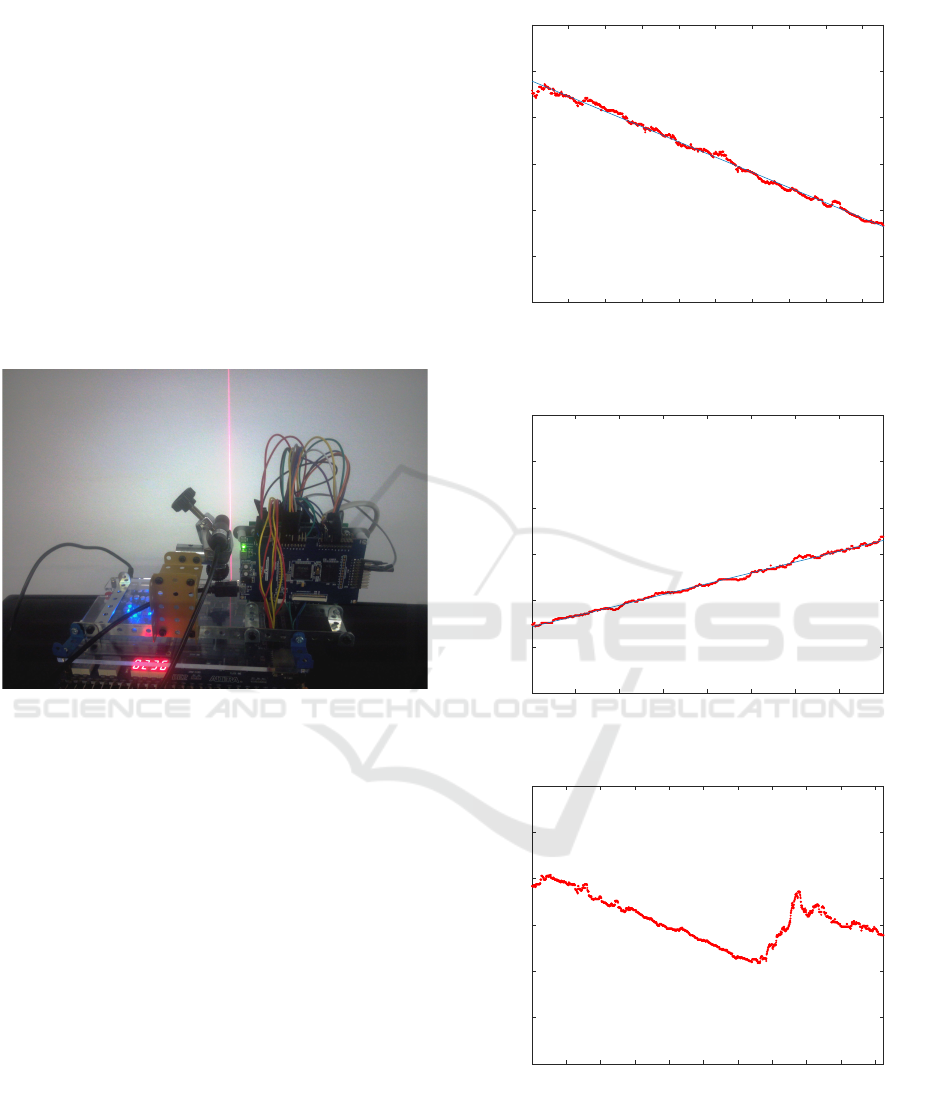
Figure 3: System in the approaching to a wall experiment.
Figure 4 shows the expected behaviour with the
moving platform approaching to a wall at a speed of
roughly 25 cm/s, and receiving pixels at a very low
speed from the sensor (a new event each 329 µs), there
is a root mean square error of 3 mm. This error is
mainly due to the first values that are not in the main
tendency, as can be seen in the figure. Without these
initial values the error drops to 2 mm.
More experiments were done as part of system
calibration, and more just to check whether the system
was working properly. Figure 5 shows the inverse ex-
periment of moving the platform away from the wall.
Again, the system shows a root mean square error of
2 mm when the system moves at roughly 20 cm/s.
Figure 6 shows the approaching to a wall experiment,
but with a 9 cm high box stuck on the wall. Initially,
the laser was fixed over the box very close to the edge
of the box. When the system is 30 cm from the box,
and with a slight angular movement, the laser is then
over the background wall. The box height can be ap-
preciated clearly in the figure, as well as the constant
approaching speed towards the wall-box set.
200 400 600 800 1000 1200 1400 1600 1800
Number of pixels (x329 us)
200
250
300
350
400
450
500
h (mm)
Figure 4: Average distance measured and recorded by the
system in the approaching a wall experiment.
100 200 300 400 500 600 700 800
Number of pixels (x657 us)
200
250
300
350
400
450
500
h (mm)
Figure 5: Moving away from the wall experiment.
200 400 600 800 1000 1200 1400 1600 1800 2000
Number of pixels (x329 us)
200
250
300
350
400
450
500
h (mm)
Figure 6: Approaching to a step experiment.
4.1 High-speed Experiments
These previous low-speed experiments have been per-
formed just to check if the system works properly.
The most interesting system feature must be shown
High-speed Motion Detection using Event-based Sensing
251
reacting as quick as events are produced. This a
very important feature in an event-based vision sys-
tem. With this almost instant response, the delay loop
control can be reduced to its minimum. This is pos-
sible because only pixels that have changed are ac-
quired and processed, in this case measuring distances
at high speed. Moreover, the system has the additional
advantage of offering a constant event rate controlled
by the processing system, with very few resources and
with a quite simple interface. To test this high-speed
distance measurement it has been used a rotating tool.
The datasheet of the tool reports a theoretical max-
imum speed of 33,000 RPM with no load. It is as-
sumed that the speed will be lower with load.
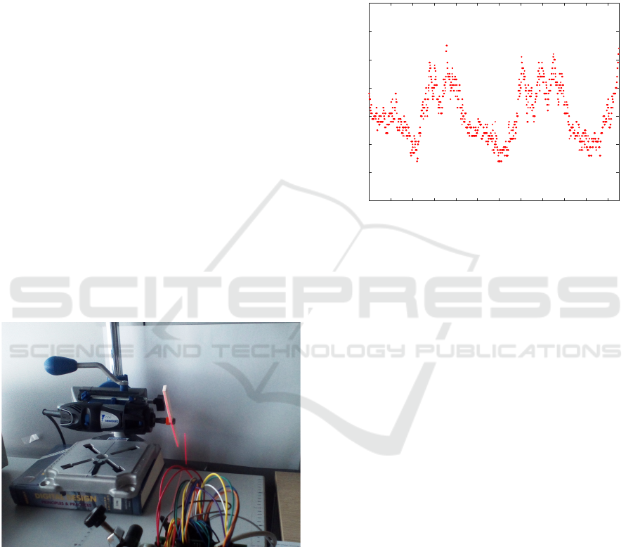
The experimental setup can be seen at figure 7.
There is a small thin plastic stick fixed to the rotat-
ing tool and the laser beam is lighting perpendicu-
larly the side of the stick. If the stick is fully verti-
cal, then the laser illuminates the maximum surface
of the stick, being detected the object at its minimum
distance. Contrarily, if the stick is totally horizontal,
it offers the minimum surface to the laser beam be-
ing mostly the background which contributes to the
object distance. In this last case the system gives the
maximum distance. Figure 7 shows the stick stopped
mounted on the tool. In this case the laser beam is
mostly over the stick edge but also it is a little bit in
the background.
Figure 7: High speed experiment setup.
Experimental results with the tool rotating can be
seen at figure 8. There is a new average distance (in
millimetres) computed each 1.7 µs. From the figure it
can be inferred a rotating speed of 21,000 rpm. It must
be noted that the experiment will show two identical
half-cycles. This is because the system, during a com-
plete stick revolution, will give two points of minimal
distance, when each edge of the stick is fully verti-
cal; and 2 points of maximum distance when the stick
is fully horizontal. With these high rotation speeds,
some uncontrolled vibrations appear which makes it
difficult for the laser to point to the side of the stick.
In this experiment, the periodicity of the movement
can be perfectly detected. An equivalent experiment
with a conventional camera would have required a
new frame each 1.7 µs, which means a working speed
of more than 588 Kfps, being this unfeasible in an
embedded system or a mobile platform.
200 400 600 800 1000 1200 1400 1600 1800 2000 2200
Number of pixels (x1.7 us)
350
360
370
380
390
400
410
420
h (mm)
Figure 8: Rotating stick at 21,000 rpm.
5 CONCLUSIONS
This paper shows an FPGA-based SCD architecture.
SCD sensing, as a particular case of event-based sens-
ing, achieves a great information reduction because it
is based on sending just the pixels that have changed
most since the last read-out. Moreover, an SCD sen-
sor sends these events ordered by the magnitude of
its change. The proposed distance computation ar-
chitecture, based on laser triangulation, can achieve
a temporal resolution of 1.7 µs, which is much better
than the offered by most traditional frame-based sys-
tems. To achieve the same temporal resolution with
a conventional camera it would be necessary a work-
ing rate of more than 500 Kfps. Our proposal achieves
this temporal resolution with very few components. A
traditional frame-based system working at this frame
rate would need much more hardware to acquire, store
and process such big data flow, which is not possible
for an embedded system.
Some experiments have been computed at low
speed and at high speed. In this last case, in order
to plot the measured distances, data are being stored
in a SRAM. Thus, in order to avoid contention, a se-
quential process of acquiring, computing and storing
data has been implemented, which delays the theoret-
ical throughput of the system to 1.7 µs. Without this
requirement of storing data, the system might work at
VISAPP 2017 - International Conference on Computer Vision Theory and Applications
252

the nominal temporal resolution of 120 ns, which is
in the order of the minimum event delay provided by
the SCD sensor.
Finally, besides being the system able of work-
ing at such high speeds, the system is small, portable,
with a synchronous control and is oriented to limited
resources systems, as autonomous robotics.
ACKNOWLEDGEMENTS
This work has been supported by the Spanish Min-
istry of Economy and Competitiveness (MINECO)
and the EU regional development funds (FEDER)
project: TEC2015-66947-R.
REFERENCES
Acosta, D., Garcia, O., and Aponte, J. (2006). Laser tri-
angulation for shape acquisition in a 3d scanner plus
scanner. In Ceballos, S., editor, CERMA2006: Elec-
tronics, Robotics and Automotive Mechanics Confer-
ence, Proceedings, pages 14–19. IEEE Computer So-
ciety. Electronics, Robotics and Automotive Mechan-
ics Conference, Cuernavaca, MEXICO, SEP 26-29,
2006.
Boluda, J. A., Pardo, F., and Vegara, F. (2016). A selective
change driven system for high-speed motion analysis.
Sensors, 16(11):1875:1–19.
Camunas-Mesa, L., Zamarreno-Ramos, C., Linares-
Barranco, A., Acosta-Jimenez, A. J., Serrano-
Gotarredona, T., and Linares-Barranco, B. (2012).
An Event-Driven Multi-Kernel Convolution Proces-
sor Module for Event-Driven Vision Sensors. IEEE
J. Solid-St. Circ., 47(2):504–517.
Camunas-Mesa, L. A., Serrano-Gotarredona, T., and
Linares-Barranco, B. (2014). Event-driven sensing
and processing for high-speed robotic vision. In 2014
IEEE Biomedical Circuits and Systems Conference
(BIOCAS), Biomedical Circuits and Systems Confer-
ence, pages 516–519. IEEE; IEEE Circuits & Syst
Soc; Nano Tera; Medtronic Inc; gsk; Ecole Polytech-
nique Federale Lausanne; CSEM; IEEE Engn Med &
Biol Soc.
Gollisch, T. and Meister, M. (2008). Rapid neural coding
in the retina with relative spike latencies. Science,
319(5866):1108–1111.
Herculano-Houzel, S. (2009). The human brain in num-
bers: a linearly scaled-up primate brain. Front. Hum.
Neurosci., 3.
Khoshelham, K. and Elberink, S. O. (2012). Accuracy and
Resolution of Kinect Depth Data for Indoor Mapping
Applications. Sensors, 12(2):1437–1454.
Liu, S.-C., Delbruck, T., Indiveri, G., Whatley, A., and Dou-
glas, R. (2015). Event-Based Neuromorphic Systems.
John Wiley & Sons Ltd., The Atrium, Southern Gate,
Chichester, West Sussex, PO19 8SQ, England, United
Kingdom.
Mahowald, M. (1992). VLSI Analogs of neural visual pro-
cessing: A synthesis of form and function. PhD thesis,
Computer Science Divivision, California Institute of
Technology, Pasadena, CA.
Pardo, F., Boluda, J. A., and Vegara, F. (2015). Selec-
tive Change Driven Vision Sensor With Continuous-
Time Logarithmic Photoreceptor and Winner-Take-
All Circuit for Pixel Selection. IEEE J. Solid-St. Circ.,
50(3):786–798.
Pardo, F., Zuccarello, P., Boluda, J. A., and Vegara, F.
(2011). Advantages of selective change driven vision
for resource-limited systems. special issue on video
analysis on resource-limited systems. IEEE T. Circ.
Syst. Vid., 21(10):1415–1423.
Serrano-Gotarredona, R., Oster, M., Lichtsteiner, P.,
Linares-Barranco, A., Paz-Vicente, R., Gomez-
Rodriguez, F., Kolle Riis, H., Delbruck, T., Liu, S. C.,
Zahnd, S., Whatley, A. M., Douglas, R., Hafliger, P.,
Jimenez-Moreno, G., Civit, A., Serrano-Gotarredona,
T., Acosta-Jimenez, A., and Linares-Barranco, B.
(2006). Aer building blocks for multi-layer multi-
chip neuromorphic vision systems. In Weiss, Y.,
Sch
¨
olkopf, P. B., and Platt, J. C., editors, Advances
in Neural Information Processing Systems 18, pages
1217–1224. MIT Press.
van Schaik, A., Delbruck, T., and Hasler, J. (2015). Neuro-
morphic Engineering Systems and Applications. Fron-
tiers in Neuroscience. Frontiers Media.
Vincent, J. F. V. (2009). Biomimetics - a review. Proceed-
ings of the Institution of Mechanical Engineers Part
H-Journal of Engineering in Medicine, 223(H8):919–
939.
Yousefzadeh, A., Serrano-Gotarredona, T., and Linares-
Barranco, B. (2015). Fast pipeline 128x128 pixel spik-
ing convolution core for event-driven vision process-
ing in fpgas. In Event-based Control, Communication,
and Signal Processing (EBCCSP), 2015 International
Conference on, pages 1–8. IEEE.
Zuccarello, P., Pardo, F., de la Plaza, A., and Boluda, J. A.
(2010a). A 32×32 pixels vision sensor for selec-
tive change driven readout strategy. In Fringe Posters
of the 36th European Sold-State Circuits Confernece
(ESSCIRC 2010).
Zuccarello, P., Pardo, F., de la Plaza, A., and Boluda, J. A.
(2010b). 32×32 winner-take-all matrix with single
winner selection. Electron. Lett., 46(5):333–335.
High-speed Motion Detection using Event-based Sensing
253
