
Towards an Automated Synthesis of a Real-time Scheduling for
Cyber-physical Multi-core Systems
Johannes Geismann
1
, Uwe Pohlmann
2
and David Schmelter
2
1
Software Engineering Research Group, Paderborn University, Zukunftsmeile 1, Paderborn, Germany
2
Software Engineering Research Group, Fraunhofer IEM, Zukunftsmeile 1, Paderborn, Germany
Keywords:
CPS, MDSD, Real-time Scheduling, Synthesis, Model-transformation, Multi-Core, Automotive.
Abstract:
Modern Cyber-physical Systems are executed in physical environments and distributed over several Electronic
Control Units using multiple cores for execution. These systems perform safety-critical tasks and, therefore,
have to fulfill hard real-time requirements. To face these requirements systematically, system engineers de-
velop these systems model-driven and prove the fulfillment of these requirements via model checking. It is
important to ensure that the runtime scheduling does not violate the verified requirements by neglecting the
model checking assumptions. Currently, there is a gap in the process for model-driven approaches to derive a
feasible runtime scheduling that respects these assumptions. In this paper, we present an approach for a semi-
automatic synthesis of behavioral models into a deterministic scheduling that respects real-time requirements
at runtime. We evaluate our approach using an example of a distributed automotive system with hard real-time
requirements specified with the MechatronicUML method.
1 INTRODUCTION
Cyber-physical Systems (CPSs) are executed in phys-
ical environments, interact with each other, and
are distributed over several Electronic Control Units
(ECUs). Often, these systems perform safety-critical
tasks under hard real-time requirements. Heteroge-
neous hardware architectures consisting of intercon-
nected multi-core ECUs are used in order to fulfill the
increasing demand for computing power.
Model-driven development methods like
MECHATRONICUML (MUML) (Becker et al.,
2014) are applied to develop the embedded software
of interconnected CPSs efficiently, correctly, and to
cope with the overall complexity. For this, a Platform
Independent Model (PIM) is developed consisting
of a component-based software architecture. Formal
verification approaches like timed model checking
(Alur and Dill, 1994) are applied to ensure the
functional correctness of the modeled behavior.
Afterwards, the PIM is refined to a Platform Specific
Model (PSM) in order to map the PIM to the under-
lying multi-core platform. Especially, a scheduling
needs to be derived for utilizing a multi-core plat-
form efficiently. Moreover, the verified safety and
real-time requirements need to be preserved in the
scheduling. However, a systematic method to derive
a feasible multi-core scheduling for interconnected
CPSs that preserves verified safety and real-time
requirements by design is missing.
In this paper, we present an approach that en-
ables a step-wise, semi-automatic synthesis of behav-
ioral models into a deterministic scheduling suited for
multi-core target platforms and respects safety and
real-time requirements. We embed our approach in
the MUML (Becker et al., 2014) and AMALTHEA
(Amalthea, 2013) toolchains and evaluate our re-
sults with an automotive example. MUML provides
a modeling language, a development process, and an
Eclipse-based tooling to design software for intercon-
nected CPSs. AMALTHEA focuses on the optimiza-
tion of timing and scheduling in embedded multi- and
many-core systems in the context of AUTOSAR (AU-
TOSAR, 2014).
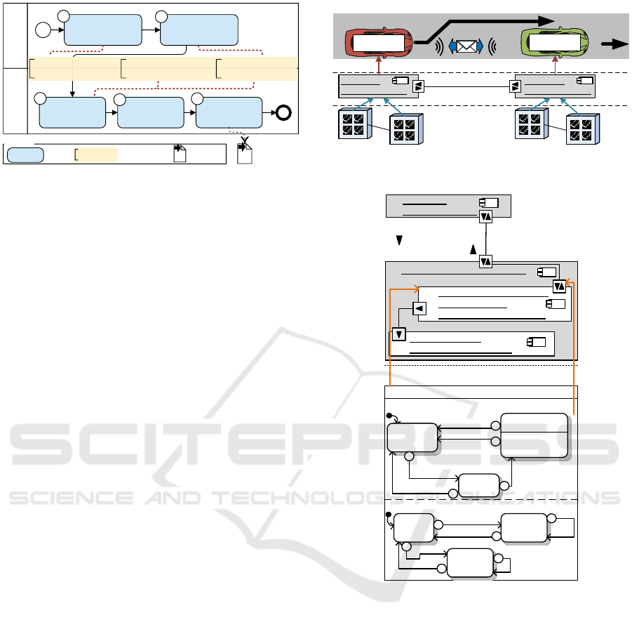
In Figure 1, we give an overview of our synthe-
sis approach by means of a Business Process Model
and Notation (BPMN) diagram. The upper BPMN
pool represents the PIM modeling. First, the soft-
ware architecture of the system is created (BPMN
Task 1). Software components with behavior in terms
of statecharts are part of this architecture. The result-
ing architecture is the input of our approach. Task 2
is the first contribution of this paper. Here, the so-
called segmentation is applied. In the segmentation,
Geismann J., Pohlmann U. and Schmelter D.
Towards an Automated Synthesis of a Real-time Scheduling for Cyber-physical Multi-core Systems.
DOI: 10.5220/0006117702850292
In Proceedings of the 5th International Conference on Model-Driven Engineering and Software Development (MODELSWARD 2017), pages 285-292
ISBN: 978-989-758-210-3
Copyright
c
2017 by SCITEPRESS – Science and Technology Publications, Lda. All rights reserved
285
Platform Inde
-
pendent Modeling
Model Application
Structure and
Behavior
Segmentation into
Runnables
Allocate
Runnables to
ECUs
Partition
Runnables to
Tasks
Map Tasks to
ECU Cores
Multi-core
Scheduling
1
2
3
4
5
I. Automatic Synthesis
of Runnables
Legend
Task
Annotated
Contribution
Output
Artifact
Platform Specific
Modeling
II. Automatic Allocation
for Multi-core Platforms
III. Ensure Real-time
Requirements
Figure 1: Process Diagram and Contributions.
the statecharts are split into small executable parts
that allow parallel execution of the modeled software.
Corresponding to the AUTOSAR specification (AU-
TOSAR, 2014), we call these parts runnables. Also,
runnable properties like a period for periodic execu-
tion are determined which are essential to ensure se-
mantically correct execution as we show in this pa-
per. The lower BPMN pool represents the PSM mod-
eling. In Task 3, the generated runnables are auto-
matically allocated to the distributed, interconnected
ECUs. This allocation is the second contribution
of this paper. In Task 4 and 5, AMALTHEA tasks
are created and mapped to ECU cores by means of
AMALTHEA’s partitioning and mapping algorithms,
respectively. The overall result of the presented pro-
cess is a deterministic scheduling that is suited for
multi-core target platforms. In Task 2 and 3 we ensure
the execution semantics and real-time requirements
of the modeled behavior in the resulting scheduling.
This is the third contribution of this paper.
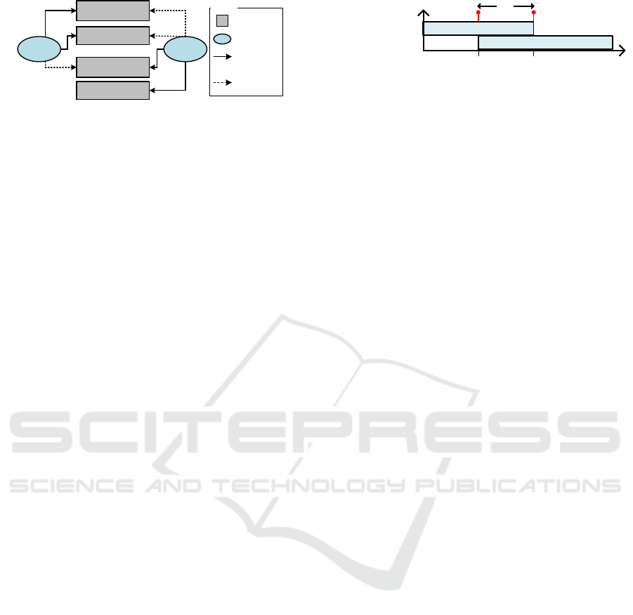
For illustrating our approach, we use the running
example shown in Figure 2. The upper part of Fig-
ure 2 depicts an autonomous overtaking scenario in-
volving two cars. The cars communicate to coordi-
nate the overtaking maneuver. In our example, the
overtaker (red) overtakes the overtakee (green) while
the overtakee guarantees that it will not accelerate
during the overtaking. This scenario is safety-critical
because an error in the communication can result in an
unsafe overtaking maneuver. We assume that the cor-
rectness of the specified software including its real-
time behavior has been formally verified on PIM level
by applying model checking (Gerking et al., 2015).
The remainder of this paper is structured as fol-
lows. In the next section, we introduce the MUML
models that are relevant and used for our synthesis
approach. In Section 3, we present our segmentation
approach. Additionally, we present our allocation ap-
proach for interconnected multi-core ECUs. In Sec-
tion 4, we evaluate our approach. In Section 5, we
discuss related work. Finally, we conclude our paper
and discuss future work in Section 6.
Software Architecture across
interconnected CPS
Overtaker
Overtakee
overtakee:
OvertakeeVehicle
overtaker:
OvertakerVehicle
Deployment to
multi-core ECUs
Figure 2: Running Example Autonomous Overtaking.
Message Types
request, finished
accept, decline
Component Instance Configuration
overtaker:
OvertakerVehicle
overtakee: OvertakeeVehicle
Real-time Statechart
init
re
quested
overtaking
request /
unsafe?/decline
done!
finished /
2
1
1
2
communicator
2
invariant
timeout 50
[timeout>25]
done!
internal
safe unsafe
1
unsafe?
1
velocity>100
velocity<=80
in
progress
safe?
1
done?
unsafe?
1
2
2
QoS Assumptions
Max. Transmission
Time: 100ms
Reliable: true
overtakeeCommunicator/
communicator :
overtakeeCommunicator
overtakeeDriver/
driver : overtakeeDriver
CommunicatorRTSC ch: done, safe, unsafe
defines behavior ofdefines behavior of
safe!/ accept
{action}[200ms]
{reset: timeout}
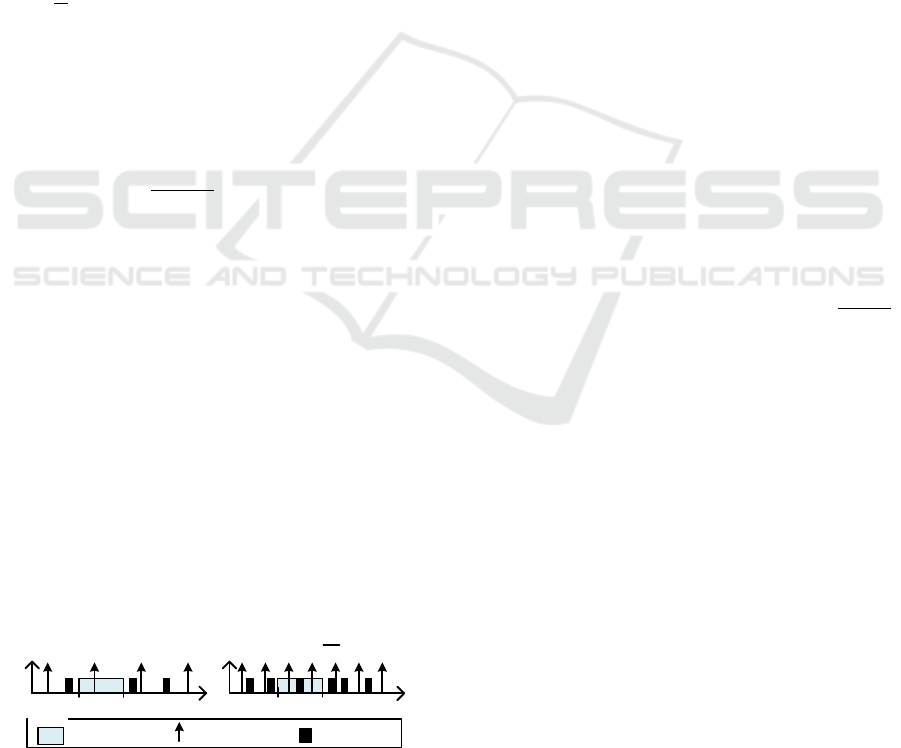
Figure 3: Overview of Software Development Views.
2 MODELING THE
APPLICATION
In this section, we give an introduction to the MUML
modeling artifacts that we use for the software spec-
ification on PIM level. Figure 3 shows an overview
of all used modeling views, artifacts, and their rela-
tions. The Component Instance Configuration view
shows the software architecture in terms of a compo-
sitional component model. In the top part, Figure 3
shows an excerpt of the software architecture realiz-
ing the overtaking scenario. It consists of the compo-
nent instances overtaker and overtakee. The compo-
nent instance overtakee is composed of the instances
overtakeeCommunicator and overtakeeDriver. Com-
MODELSWARD 2017 - 5th International Conference on Model-Driven Engineering and Software Development
286

ponent instances have ports that can send and receive
typed messages. Connector instances connect ports
and have Quality of Service (QoS) assumptions like a
maximum transmission time. For example, the over-
taker sends the messages request and finished to the
overtakee and can receive the messages accept or de-
cline from the overtakee. Based on the QoS assump-
tions, the model checking assumes that messages are
transmitted within 100ms. Furthermore, component
instances can be connected to continuous component
instances that represent sensors and actuators of the
CPS. For the reason of comprehensibility, we omit
these components in the diagram.
The component’s behavior is specified in terms
of Real-time Statecharts (RTSCs) which combine
UML state machines (OMG, 2011) and timed au-
tomata (Alur and Dill, 1994). Figure 3 shows the be-
havior of component instance overtakee. RTSCs can
be composed of so-called regions that again contain
state machines. For instance, CommunicatorRTSC is
composed of the regions communicator and internal.
The region communicator represents the behavior of
the communication with the overtaker and is com-
posed of the states init, overtaking, and requested. The
region internal represents the internal behavior of the
component instance that takes the decision whether
the overtaking is safe or not and is composed of the
states safe, unsafe, and in progress. RTSCs may share
variables (e.g., velocity in region internal) and have
clocks that measure the time and can be reset to zero
within the statechart, e.g., timeout in the region com-
municator. Furthermore, each RTSC has exactly one
currently active state. A state may contain an invari-
ant as a real-time property, which restricts the value
of the clock when the state is active. It must be guar-
anteed during runtime that an invariant is never vio-
lated, e.g., the state overtaking has to be left before the
clock timeout reaches 50ms. A transition may have a
guard ([velocity > 100]) , time constraints ([timeout >
25]), a trigger message (trigger /), and a synchroniza-
tion channel that restricts the firing (sender channel!
/, receiver channel? /). It is enabled, i.e., it is able to
fire, if its source state is active, its guard evaluates to
true, its time constraint evaluates to true, and its trig-
ger message is stored within the buffer. Furthermore,
some transitions are connected with each other via
synchronization channels; the transition from the state
requested to the state overtaking in region communi-
cator is synchronized with the transition from state
safe to overtaking in region internal via the synchro-
nization channel safe. Thus, these transitions may
only fire jointly.
We assume that RTSCs are executed step-wise,
i.e., in each step the outgoing transitions of the cur-
rently active state (and all synchronized transitions)
are evaluated. If a transition is enabled, the transition
with the highest priority fires and the currently acti-
vate state gets updated.
3 SEGMENTATION AND
ALLOCATION
In this section, we explain our proposed approach for
segmentation and allocation in more detail. We as-
sume that models for the PIM are already created and
requirements are verified using model checking (cf.
BPMN Task 1, Figure 1). The remainder of this sec-
tion is structured by following the development pro-
cess as shown in Figure 1.
3.1 Segmentation into Runnables
The segmentation defines which part of the software
models are mapped to a runnable. Runnables are the
smallest unit that can be executed by the system and,
therefore, segmenting the PIM into runnables affects
the behavior execution on the target platform directly.
Additionally, WCET, period, and deadline are defined
for each runnable. This step is crucial for seman-
tically correct execution because an invariant might
be violated if a runnable is executed too late. Thus,
the segmentation has to fulfill the following require-
ments. R1: The segmentation has to allow parallel
execution. Multi-core environments increase the per-
formance of a system by using parallelization. There-
fore, software has to be separated into runnables that
can be executed in parallel. R2: We aim to generate
as few runnables as possible without degrading the
possibility of parallel execution because with an in-
creasing number of runnables, the complexity of the
partitioning step also increases, which makes it more
difficult to find a feasible scheduling and may lead to
a decrease in the performance of the system.
R3: Real-time requirements must be fulfilled at
runtime. On PIM level, model checking techniques
are used to ensure the fulfillment of these require-
ments at design time. Executing the software on a
platform adds further parameters that have not been
considered during the verification step on PIM level,
e.g., the activation due to the concrete scheduling.
Thus, a requirement for the resulting scheduling is to
ensure that the semantics of the PIM are respected.
In a first step, MUML software models have to be
split into runnables. RTSCs of the software architec-
ture are the starting point for the segmentation. The
segmentation directly adresses the first and second re-
quirement because it defines which parts of the soft-
Towards an Automated Synthesis of a Real-time Scheduling for Cyber-physical Multi-core Systems
287
Current State of
Communicator
Current State of
internal
timeout
velocity
commu
nicator
internal
Legend
Label
Runnable
Label
Access
Inherited
Label
Access
Figure 4: Runnables have to Specify Label Accesses.
ware can be executed in parallel. We propose to gen-
erate one runnable per region of every RTSC because
it allows parallel execution of component behavior
without increasing the number of runnalbes signifi-
cantly. Furthermore, this segmentation is reasonable
because each port behavior is described in exactly one
region. Hence, we generate one runnable per port
behavior and, therefore, the different communication
protocols of a component can be executed in parallel.
In addition, we generate one runnable per continuous
component that is used to read sensor values period-
ically. Executing the runnable for a region will exe-
cute one step of the corresponding RTSC, i.e., eval-
uating and possibly firing outgoing transitions of the
currently active state.
The resulting runnables may have dependencies
since they may share RTSC variables. These de-
pendencies are important for partitioning and map-
ping because runnables accessing the same variable
are not suitable to be executed in parallel. Corre-
sponding to AUTOSAR, we call such variables la-
bels. At first, we define labels and label-accesses of
runnables. Furthermore, RTSCs may use shared vari-
ables and real-time clocks, for which labels are gener-
ated also. These label-accesses are specified for every
runnable. Figure 4 shows the label accesses for the
example RTSC in Figure 3. Both runnables define a
label access to their current state label. The runnable
for region communicator defines a label access to the
label for the clock timeout. The runnable for region
internal defines a label access to the variable velocity.
Additionally, both runnables specify inherited la-
bel accesses, which are needed, if synchronization
channels are used. Since two transitions have to be
fired jointly, we propose to extend the models and im-
plementation for runnables by the possibility to eval-
uate and fire all synchronized transitions. In Fig-
ure 3, the transition from state overtaking to init in
region communicator are synchronized with the tran-
sition from state in progress to safe via the synchro-
nization channel done. Hence, both runnables inherit
the label accesses from the other runnable.
In a second step, we derive runnable properties.
Since these properties directly affect the scheduling,
their correct determination is crucial for preserving
model checking results at runtime. Every runnable
time
timeout<= 50
Clock Constraint
Invariant
timeout > 25
25 ms 50 ms
I
min
I
max
I
E
Figure 5: Finding the Enabling Interval of a Transition.
has to provide a period, a deadline, and a WCET that
are used for partitioning, mapping, and further anal-
yses. Our approach provides an automatic technique
to determine a period and deadline for each runnable.
Determining a platform-specific WCET is a complex
topic and out of scope of this paper. In our ap-
proach, we assume that the WCET for each runnable
is determined by an appropriate method (e.g., Sim-
ple Scalar (Austin et al., 2002) or aiT (Ferdinand and
Heckmann, 2004)) and provided as an annotation for
each runnable.
The period describes how frequently a runnable is
executed. We provide an automatic technique to de-
termine a period, such that all real-time requirements
are fulfilled at runtime without increasing the proces-
sor utilization unnecessarily. Determining the period
has to respect the semantics of the transition condi-
tions, i.e., guards, deadlines, clock constraints, and
invariants. Since a runnable is executed periodically,
we have to guarantee that it is executed whenever a
transition is enabled.
Based on the transition conditions, we can deter-
mine an enabling interval I
E
which describes the time
span when a transition is enabled. We determined
a computation rule how I
E
can be computed for all
combinations of transition conditions. In general, we
define I
E
= I
max
− I
min
, where I
min
is the first point in
time and I
max
is the last point in time when all transi-
tion conditions validate to true. As an example, con-
sider the combination of a clock constraint and a state
invariant, e.g., the transition from state overtaking to
init in region communicator with priority 1 in Figure 3.
The transition has a clock constraint that is enabled
when the clock timeout is greater than 25ms. Addi-
tionally, the state overtaking has an invariant that is
valid when the clock timeout is less or equal 50ms.
Figure 5 shows the time frames when each constraint
validates to true. Hence, I
min
is at 25ms and I
max
is at
50ms. Thus, the valid enabling interval I
E
has a length
of 25ms. If several clock constraints are used, we
can generalize I
min
to the infimum of all greater-or-
equal constraints and I
max
to the supremum of all less-
or-equal constraints. Similar to this, we defined for
all other transition conditions a similar computation.
Since guards can depend on sensor values, guards also
depend on the period of the runnable of the corre-
sponding continuous component. Thus, guards have
to be considered in the computation of I
min
and I
max
.
MODELSWARD 2017 - 5th International Conference on Model-Driven Engineering and Software Development
288
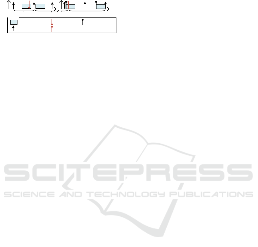
It is crucial that the runnable is executed during
I
E
for each transition because an enabled transition
might become disabled again before firing. Other-
wise, the assumptions used during model checking
would be neglected. Thus, based on I
E
we determine
a period for the runnable. For this, we set the period
to half of the length of the shortest enabling interval
I
E
. Figure 6 illustrates that a well-chosen period is
essential to guarantee the firing of an enabled tran-
sition. It shows two different cases of the execution
for the runnable that handles the transition of the ex-
ample above. Each case shows the enabling interval
of the transition, the periodic activation times of the
runnable, and the concrete execution of the runnable.
On the left, the period is set to I
E
. Here, the enabling
interval of the transition is missed because the tran-
sition is evaluated too late. Therefore, the invariant
of the state gets violated. On the right, the period is
set to
I
E
2
which ensures that the runnable is executed
at least once during the enabling interval because a
runnable will be executed completely before it is ac-
tivated again.
Since the period π
r
has to respect all transitions of
the runnable, the period of a runnable r is defined as
the minimum of all period values:
π
r
= min{
min(I
E
)
2
|∀I
E
∈ runnable}, (1)
The current approach is limited to local (within one
region) clocks and to clocks that get reset when enter-
ing the state. Otherwise, the enabling interval cannot
be determined precisely. If global clocks should be
supported in the future, a solution could be to apply a
reachability analysis to find all possible clock zones.
Every runnable defines a deadline. Similar to the
period of a runnable, the deadline depends on the exe-
cution of each transition of an RTSC since every tran-
sition can define a dedicated deadline. Consequently,
the runnable has to be finished before the deadline of
the firing transition expires. Thus, the deadline of a
runnable is defined as the minimum deadline of all
transitions that are evaluated by this runnable. If no
deadline is specified, we set the deadline to the value
of the runnable, since the runnable has to be finished
before it is activated again.
time
time
Runnable
Is Activated
Legend
Runnable is
Executed
50ms
25ms 50ms
25ms
Period = I
E
Period =
I
E
2
Transition
is Enabled
Figure 6: Length of Period Affects the Execution.
3.2 Allocate Runnables to ECUs
After the segmentation, we have to define which
runnable is executed on which ECU (cf. BPMN Task
3, Figure 1). Furthermore, hard real-time require-
ments of the communication have to be respected.
In the following, we derive two constraints that
an allocation of runnables to ECUs have to fulfill:
1. A constraint regarding a necessary condition for
schedulability. 2. A constraint that ensures the max-
imum time for communication at runtime. Based on
runnable properties, the constraints are used to guar-
antee the maximum transmission time and schedula-
bility of the system with regard to the real-time re-
quirements during the allocation.
When allocating runnables to ECUs, it is required
that all ECUs have enough processing capacity to ex-
ecute all allocated runnables. The runnables for each
allocated component will decrease the available pro-
cessing capacity of the ECU. We restrict the allo-
cation regarding a necessary condition for schedu-
lability: The amount of computing time of the ex-
ecuted software must not exceed the processing ca-
pacity of the ECU. We define the processing capac-
ity of each ECU core as 1. For simplicity, we as-
sume that all ECUs use homogeneous cores. Thus,
all cores have the same processing capacity and, con-
sequently, the processing capacity of each ECU is de-
fined as C
ECU
= |ECUCores|. The utilization factor
of a runnable U
r
describes how much percentage of
C
ECU
is needed to execute this runnable. We define
U
r
of runnable r for a specific ECU as U
r
=
WCET
r,e
π
r
,
where WCET
r,e
is the upper bound of the execution
time of runnable r on ECU e and π
r
is the period of
runnable r. If the sum of the utilization factors of
all runnables exceeds the processing capacity of the
ECU, it is impossible to find a valid scheduling for a
given set of runnables. Hence, this sum has to be less
than the processing capacity of the ECU.
∑
r∈Runnables(ECU)
U
r
< k ∗C
ECU
, k ∈ [0; 1] (2)
k is a constant factor that can be defined by the de-
veloper to adjust this constraint for her needs, e.g., to
restrict the maximal processor utilization.
Another crucial aspect is the communication time
between two components. The allocation affects the
communicating time that is needed for communica-
tion. In MUML, the maximum transmission time is
constrained by the QoS of a connector instance, de-
noted by T
ConInst
, e.g., 100ms for the communication
between component instances overtaker and overta-
kee in Figure 3. For the communication, we assume
that each components port behavior (one region of
the RTSC) is executed by one runnable: a sender
Towards an Automated Synthesis of a Real-time Scheduling for Cyber-physical Multi-core Systems
289
time
Sender Runnable r
S
Receiver Runnable r
R
t
s
t
r
Runnable
Is Activated
Message
Gets Sent
Message Is
Put in Buffer
Runnable
Checks Buffer
Legend
Runnable
Is Executed
t
trans
...
Figure 7: Upper Bound of Time for Sending and Receiving.
runnable r
S
that sends the message and a receiver
runnable r
R
that receives and processes the message.
Additionally, we assume that a lower layer is used to
handle the transmission of the message from r
S
to r
R
,
e.g., a middleware. Based on (Tindell et al., 1995),
we define that delivering a message relies on time for
generating and sending the message t
s
, transmitting it
from sender to receiver t
trans
, and queuing it until the
receiving process recognizes the message t
r
. Figure 7
illustrates the derivation of t
s
, t
trans
, and t
r
. When a
message is sent by r
S
, we assume that the middleware
sends the message directly after a task has finished.
Thus, the message is processed by the middleware at
least before the runnable is executed again. Hence,
t
s
can be estimated by the period of the runnable π
s
.
t
trans
is based on the used middleware and the underly-
ing communication protocol. We assume that an up-
per bound constant can be statically determined for
each communication channel and used middleware.
t
r
describes the time it takes from the point in time
when the message is put into the message buffer until
runnable r
R
recognizes the message. Let us assume
that the message is put into the buffer immediately af-
ter r
R
checked the buffer as depicted in the right part
of Figure 7. Hence, in this execution, the message
is not received by the runnable. Since r
R
is activated
periodically, it has to be finished completely within
the next period interval. Consequently, the time until
the message buffer is checked again by the runnable
is smaller than 2 ∗ π
receiverrunnable
. Hence, we use this
time as an upper bound for t
r
and state the constraint:
π
s
+t
trans
+ 2 ∗π
r
≤ T
ConInst
(3)
Both proposed constraints (Equations 2 and 3)
are implemented using the allocation approach of
MUML (Pohlmann and Hüwe, 2015), which al-
lows specifying allocation constraints for compo-
nents, e.g., which components have to be allocated to
the same ECU. Thereby, we introduce additional al-
location constraints in order to realize an automatic
allocation of runnables. We use the heuristic that
runnables that belong to the same component instance
have to be allocated to the same ECU because a soft-
ware component instance has a strong coherence (Gill
and Grover, 2003). Hence, in this step, we still allo-
cate components to ECUs with respect to the runnable
properties.
3.3 Partitioning and Mapping
For each ECU, further actions are needed to refine
the models to schedulable software: Partitioning of
runnables to tasks and mapping these tasks to ECU
cores such that all constraints are fulfilled (cf. BPMN
Task 4 and Task 5, Figure 1). Finally, the deployment
of the software takes place which includes the genera-
tion of source code for a given multi-core scheduling.
We utilize concepts and tooling of AMALTHEA for
partitioning and mapping and concepts and tooling for
code generation of AMALTHEA and MUML. Hence,
we provide an automatic model-to-model transforma-
tion from MUML to AMALTHEA in order to reuse ex-
isting algorithms for partitioning and mapping.
The output of the allocation task describes the al-
location of runnables to ECUs. For the execution,
these runnables have to be grouped to tasks, which
is done in the partitioning. For this, we automati-
cally transform the runnable models from MUML to
AMALTHEA by providing a model-to-model transfor-
mation. Then, an algorithm to find a feasible parti-
tioning of AMALTHEA (Höttger et al., 2015) can be
applied. In this algorithm, runnables are grouped to
tasks based on their properties and dependencies.
After that, in the mapping, the newly created tasks
are mapped to the cores of the ECU. AMALTHEA pro-
vides an algorithm to allocate a set of tasks to the
cores of one multi-core ECU regarding specific op-
timization criteria, like load balancing. The result of
this algorithm is a scheduling for each ECU.
4 EVALUATION
We conducted a case study to evaluate our approach
using the overtaking example. In our case study,
we focused on the correctness of the synthesis. We
assume the synthesis to be correct if all relevant
elements are considered in the applied transforma-
tions and all computed values are correct. We
based our case study on guidelines by Kitchenham et
al. (Kitchenham et al., 1995) and the Goal-Question-
Metric (GQM) method (Van Solingen et al., 1999) for
the structured definition of quality metrics. We state
two hypotheses to be validated by the case study. H1:
We expect, that for the segmentation approach a fea-
sible multi-core scheduling can be found. H2: We
expect that applying the allocation approach, the re-
sult is a correct allocation that respects both stated
constraints (cf. Equations 2 and 3), if such an al-
location exists. We evaluated schedules for differ-
ent platforms. In the following, we show the result-
ing tasks for one multi-core ECU of the overtaker
MODELSWARD 2017 - 5th International Conference on Model-Driven Engineering and Software Development
290

Table 1: Tasks Resulting by Partitioning.
Core Task Component Period (ms)
Core 1
T3 Communicator 500
T6 Driver 500
Core 2
T0 Driver 25
T1 Communicator 25
T2 Driver 12
T4 Communicator 500
T5 Communicator 500
software component instance of the running example.
The segmentation of the overtaker components results
in 11 runnables, 37 labels, and 39 label accesses.
We applied the segmentation to several addi-
tional component models and compared them to man-
ually created reference models. For each model,
the segmentation resulted in the expected number
of runnables, labels, and label accesses. Addition-
ally, the generated runnable properties were correct
and due to the construction of period and deadline
all real-time assumptions hold at runtime. Partition-
ing and mapping of AMALTHEA resulted in a fea-
sible scheduling with 7 tasks. 5 tasks are mapped
to one core and 2 tasks to the other. Table 1 shows
the resulting tasks, their properties, and the executing
ECU core. Both cores execute runnables of the com-
ponent instance overtakeeCommunicator and overta-
keeDriver. Hence, the execution of the software uses
the benefits of parallel execution, which reduced the
response time of the system. Overall, we argue that
H1 is fulfilled. For evaluating the allocation ap-
proach, we considered QoS assumptions of connec-
tors. For each connector, the expected constraints
were generated. Additionally, we used different val-
ues for the periods of the sender runnable and re-
ceiver runnable, as well as for the underlying plat-
form model to test the cases that (A) a valid alloca-
tion with two ECUs is found, (B) a valid allocation
with only one ECU is found, and (C) no valid alloca-
tion is found. For each value combination, the results
are as expected. Thus, we state that H2 is fulfilled.
The case study shows that our concepts and the im-
plementation work as expected. Due to the higher de-
gree of automation in the whole development process,
there are less manual steps in comparison to state of
the art approaches. Additionally, the systems engi-
neer needs less domain knowledge for embedded sys-
tems and scheduling. The main threats to validity
are: 1. We applied our approach to a small exam-
ple. 2. We assume that the partitioning and map-
ping of AMALTHEA consider all specified constraints
correctly, and 3. We assume that the code genera-
tion is correct. Overall, we argue that our approach
helps to increase the automation of finding a feasible
scheduling for software with real-time requirements
for multi-core platforms. The concepts are evaluated
using MUML and AMALTHEA, but can be adopted to
other approaches. We provide an Eclipse bundle that
contains our implementation and model files of the
running example (Geismann et al., 2016).
5 RELATED WORK
Our approach is related to component-based ap-
proaches for CPS and to approaches for scheduling
and safe deployment of CPS.
ProCom (Bureš et al., 2008) provides a compo-
nent model for the development of embedded real-
time systems. ProCom provides a modeling language
that is based on Final State Machines enriched by fea-
tures of Timed Automata to compute (real-time re-
lated) dependencies of the model that can affect the
scheduling. Additionally, ProCom provides a code
synthesis that aims to preserve the semantics of Pro-
Com at runtime. The code for every component is
executed concurrently. In contrast to our approach,
the resulting system is mainly event-triggered, which
does not allow a static scheduling analysis. MEM-
CONS (Macher et al., 2015) provides a model-driven
framework for embedded systems. It follows the AU-
TOSAR methodology and provides an automatic ap-
proach for mapping tasks to multi-core ECUs. Fur-
thermore, an analysis of timing constraints can be
applied to the deployed system. In contrast to our
approach, the behavior of the software components
is not specified model-driven and cannot be used for
segmentation. In both approaches the behavior is not
specified model-driven. Thus, a segmentation of ver-
ified models is not possible.
Another related area is the safe deployment to
real-time systems, where approaches focus on the
modeling of (real-time) operating system elements to
improve the deployment of the software. In (Lelion-
nais et al., 2012) a DSL is used to describe the be-
havior of the RTOS in a platform model, i.e., tasks
and semaphores. Thus, model checking can be ap-
plied which considers both the application behavior
and the behavior of the underlying system. In contrast
to our approach, distributed systems and multi-core
ECUs are not taken into account. (Lukasiewycz et al.,
2013) present an approach to derive task priorities in
event-triggered systems. The input for the algorithm
is a task graph and a mapping. The task graph de-
scribes all tasks of the system and their communica-
tion. The mapping describes the assignment of tasks
and messages to resources, e.g., ECUs or busses. The
authors provide an algorithm to find optimal priorities
Towards an Automated Synthesis of a Real-time Scheduling for Cyber-physical Multi-core Systems
291

for tasks in event-triggered systems. In contrast, we
focus on time-triggered systems and do not consider
priorities of tasks.
6 CONCLUSION AND OUTLOOK
In this paper, we presented a systematic approach that
enables a step-wise, semi-automatic synthesis of be-
havioral models into a deterministic scheduling suit-
able for multi-core target platforms. We illustrated
our approach based on an automotive, autonomous
overtaking example and evaluated it based on the
MUML and AMALTHEA platforms.
Firstly, we showed how runnables, runnable prop-
erties, and runnable dependencies are synthesized
from RTSCs to derive a segmentation that allows par-
allel execution of software components. We identified
limitations in our approach when using clocks across
multiple states. Secondly, we introduced an approach
for the allocation of runnables to interconnected
multi-core ECUs. Especially, we identified and auto-
matically derived necessary conditions an allocation
has to fulfill in order to guarantee a valid schedul-
ing. Thirdly, we introduced an approach that pre-
serves verified real-time requirements on PIM level
during the synthesis and in the resulting scheduling.
In future work, we want to introduce a reachabil-
ity analysis to cope with the mentioned limitations re-
garding clocks. Also, we want to address dynamic
scheduling in case of event-triggered systems. Fi-
nally, we plan to extend the allocation constraints for
ECUs that use cores with different processing capac-
ities and by estimating the transmission time dynami-
cally during the allocation.
ACKNOWLEDGEMENTS
We thank Andreas Dann for feedback on drafts of
the paper. This work was partially developed in the
Leading-Edge Cluster ’Intelligent Technical Systems
OstWestfalenLippe’ (IT’S OWL) and in the ITEA 2
AMALTHEA4public project (No. 01IS14029I). The
IT’S OWL and the AMALTHEA4public projects are
funded by the German Federal Ministry of Education
and Research.
REFERENCES
Alur, R. and Dill, D. (1994). A theory of timed automata.
Theoretical computer science, 126(2):183–235.
Amalthea (2013). Deliverable: D3.1 concept for a partition-
ing/ mapping/ scheduling/ timing-analysis tool. Tech-
nical Report 3.4, Amalthea.
Austin, T., Larson, E., and Ernst, D. (2002). Simplescalar:
an infrastructure for computer system modeling.
AUTOSAR (2014). Release 4.2 Overview and Revision
History.
Becker et al. (2014). The mechatronicuml design method -
process and language for platform-independent mod-
eling. Technical Report tr-ri-14-337, Heinz Nixdorf
Institute, Paderborn University. Version 0.4.
Bureš et al. (2008). Procom–the progress component model
reference manual. Mälardalen University, Västerås,
Sweden.
Ferdinand, C. and Heckmann, R. (2004). ait: Worst-case
execution time prediction by static program analysis.
In Jacquart, R., editor, Building the Information Soci-
ety, volume 156 of IFIP International Federation for
Information Processing, pages 377–383. Springer US.
Geismann et al. (2016). Implementation and example
models. https://trac.cs.upb.de/mechatronicuml/wiki/
PaperModelsward17.
Gerking et al. (2015). Domain-specific model checking for
cyber-physical systems. In Proceedings of the 12th
Workshop on Model-Driven Engineering, Verification
and Validation, volume Vol-1514 of MoDeVVa ’15.
Gill, N. S. and Grover, P. S. (2003). Component-based mea-
surement: Few useful guidelines. SIGSOFT Software
Engineering Notes, 28(6):1–6.
Höttger et al. (2015). Model-based automotive partitioning
and mapping for embedded multicore systems. Inter-
national Journal of Computer, Electrical, Automation,
Control and Information Engineering, 9(1):268–274.
Kitchenham et al. (1995). Case studies for method and tool
evaluation. IEEE Software, 12(4):52–62.
Lelionnais et al. (2012). Formal Behavioral Modeling of
Real-Time Operating Systems. In Proceedings of the
14th International Conference on Enterprise Informa-
tion Systems (ICEIS (2) 2012), Wroclaw, Poland.
Lukasiewycz et al. (2013). Priority assignment for event-
triggered systems using mathematical programming.
In Proceedings of the Conference on Design, Automa-
tion and Test in Europe, DATE ’13, pages 982–987,
San Jose, CA, USA. EDA Consortium.
Macher et al. (2015). Filling the gap between automotive
systems, safety, and software engineering. e & i Elek-
trotechnik und Informationstechnik, pages 1–7.
OMG (2011). Unified Modeling Language, version 2.4.1.
Superstructure Specification.
Pohlmann, U. and Hüwe, M. (2015). Model-driven al-
location engineering. In Proceedings of the 30th
IEEE/ACM International Conference on Automated
Software Engineering (ASE 2015). ACM/IEEE, IEEE.
Tindell et al. (1995). Analysis of hard real-time communi-
cations. Real-Time Systems, 9(2):147–171.
Van Solingen et al. (1999). The Goal/Question/Metric
Method: a practical guide for quality improvement of
software development. McGraw-Hill.
MODELSWARD 2017 - 5th International Conference on Model-Driven Engineering and Software Development
292
