Thermal Stability Simulation of MEMS Micro Scanner
Multi-physics Simulations Coupled with Experimental Verifications
Seungoh Han
1
, Chang-Hyeon Ji
2
, Jae-Hyoung Park
3
and Jong-Uk Bu
4
1
Dept. of Robotics Eng., Hoseo University, 20 Hoseo-ro 79 Beon-gil, Asan, Chungnam, Republic of Korea
2
Dept. of Electronics Eng., Ewha Womans University, 52 Ewhayeodae-gil, Seodaemun-ku, Seoul, Republic of Korea
3
Dept. of Electronics and Electrical Eng., Dankook University, 152 Jukjeon-ro, Yongin, Gyeonggi, Republic of Korea
4
Senplus Inc., 109 Gwanggyo-ro, Suwon, Gyeonggi, Republic of Korea
Keywords: Thermal Stability, Multi-physics, MEMS, Micro Scanner, Pico Projector.
Abstract: A practical application of multi-physics simulations was presented. In order to analyse thermal stability of
MEMS micro scanner, multi-physics simulation procedure was proposed and then verified by comparing
the simulated results to the measured data. The proposed procedure started from defining simulation
parameters and was verified stepwise by comparing the interim results with the related experimental data,
which has increased the accuracy of the proposed, multi-physics simulation procedure. Based on those
results, we could got more insight into the thermal stability issue and the allowable bias limit could be
determined, which does not deteriorate the device performance significantly. The proposed simulation
procedure is expected to contribute for successful commercialization of MEMS micro scanner by increasing
its thermal stability.
1 INTRODUCTION
Continuously progressed miniaturization
technology, combined with MEMS (Micro-Electro-
Mechanical System)-based micro scanner, made it
possible to realize pico projector (Davis et al, 2008).
Furthermore, it has recently gotten a huge amount of
interest due to the emerging era of virtual reality
(Saeedi et al., 2014). Among major components
consisting of pico projector, micro scanner plays a
core role of scanning images on optical plane.
Except pico projector, micro scanner have also lots
of applications such as Light Detection And Ranging
(LIDAR) (Moss et al., 2012), optical coherence
tomography (OCT) (Strathman et al., 2015), and
other medical applications (Pengwang et al., 2016).
Therefore, many research groups have been working
on micro scanner and several types of micro scanner
have been developed (Holmström et al., 2014).
However, just few of the scanners are
commercially available due to the issues of robust
operation, mass-producibility, low cost, high yield,
and so on. Robust operation of a micro scanner
should be confirmed but its multi-physics nature
prevents the reliability issue to be solved easily
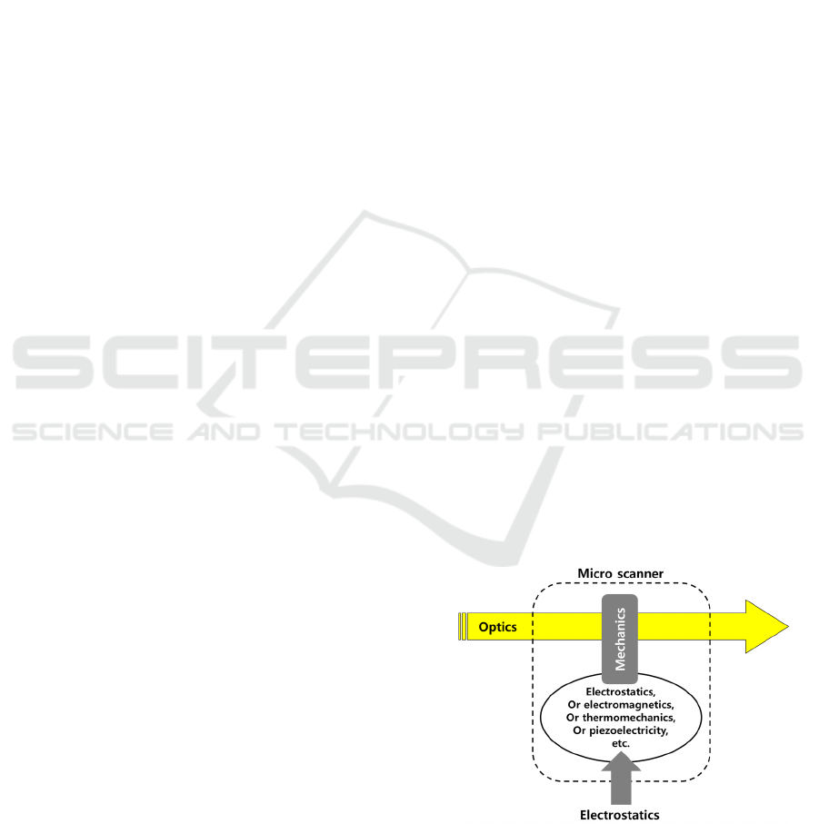
(Kurth et al., 2007). Micro scanners are generally
driven by the electrical signal(s) and accordingly
handle the input optical signal(s) through its
mechanical operations. On the way of converting the
driving electrical signal to the corresponding
mechanical operation, different types of actuation
mechanism can be utilized such as electromagnetics,
thermomechanics, piezoelectricity, and electrostatics
as shown in Figure 1.
Figure 1: Multi-physics nature of a micro scanner.
In this paper, thermal stability analyses based on
multi-physics simulations are presented and verified
with experimental measurements. The presented
84
Han, S., Ji, C-H., Park, J-H. and Bu, J-U.
Thermal Stability Simulation of MEMS Micro Scanner - Multi-physics Simulations Coupled with Experimental Verifications.
DOI: 10.5220/0005962700840088
In Proceedings of the 6th International Conference on Simulation and Modeling Methodologies, Technologies and Applications (SIMULTECH 2016), pages 84-88
ISBN: 978-989-758-199-1
Copyright
c
2016 by SCITEPRESS – Science and Technology Publications, Lda. All rights reserved
analyses started from establishing a proper
procedure on the basis of the related governing
equations and completed with the experimental
verifications. With the proposed procedure, we can
get more information related with the thermal
stability and thereafter improve the robustness of
micro scanner for its successful commercialization.
2 GOVERNING EQUATIONS
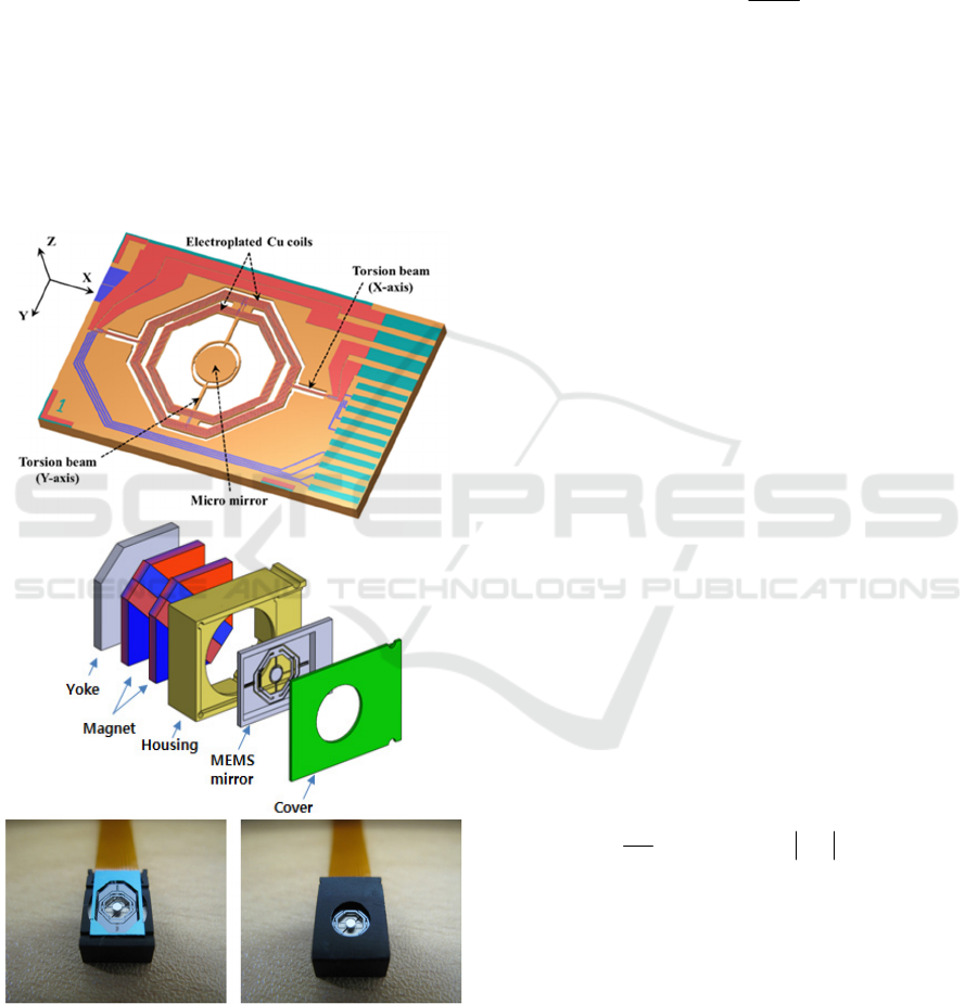
Figure 2 shows the micro scanner to be analysed.
It’s an electromagnetically-actuated biaxial micro
scanner having mechanical amplification mechanism
by driven at the resonance (Cho et al., 2015).
Figure 2: Electromagnetically-actuated micro scanner; (a)
schematic view of the micro scanner, (b) schematic view
of packaging the micro scanner, (c) the fabricated micro
scanner.
When applying the driving voltage to the coils,
current flowing generates electromagnetic field and
therefore Lorentz force is induced through magnetic
interaction with the underlying permanent magnet
assembly (Magnet in Figure 2b). Torque
caused by
the induced Lorentz force acts on torsion beams as
the following (Ji et al., 2007):
Bld
TR
V
rFdrd
)(
(1)
Where
- r is the radius of torsion;
- F is Lorentz force;
- V is the applied driving voltage;
- R(T) is the resistance of the coil;
- l is the length of coil;
- B is the magnetic flux.
The resistance of the coil is a function of
temperature T as the following:
)](1[)(
00
TTRTR
(2)
Where
- R
0
is the reference resistance at T
0
;
-
is the temperature coefficient of resistance;
- T
0
is the reference temperature.
Alternatively, it can be expressed in terms of
electrical conductivity
rather than the resistance as
following:
)](1[)(
00
TTT
(3)
Where
0
and
are reference electrical
conductivity and temperature coefficient of electrical
conductivity, respectively, as in the case of
resistance.
The temperature of the micro scanner can be
determined from the balance of thermal energy as
the following (Varona et al, 2007):
2
2
)( VTTk
t
T
c
(4)
Where
-
, c, and k are density, specific heat capacity and
heat conductivity of the device, respectively;
-
(T) is the temperature-dependent electrical
conductivity defined as Equation (3).
Added to the above energy balance equation,
convective heat transfer to the surrounding given as
q=hT should be included as one of thermal
boundary conditions, where q is the heat flux and h
is the convection coefficient.
Finally, the resulting mechanical torsion angle
(a)
(
b
)
(c)
Thermal Stability Simulation of MEMS Micro Scanner - Multi-physics Simulations Coupled with Experimental Verifications
85
can be determined by Newton’s 2
nd
law as the
following:
)()(
2
2
TK
dt
d
C
dt
d
TI
(5)
Where
- I(T) is the moment of inertia;
- C is the damping coefficient;
- K(T) is the stiffness of torsion beams.
The stiffness of torsion beams and the moment of
inertia are given as a function of temperature
because thermal expansion coefficient and
temperature coefficient of Young’s modulus change
the elastic property as well as the dimensions
(Bourgeois et al., 1997). As a result, resonant
frequency of the device can be varied as the
temperature changes (Zhang et al., 2013).
3 THERMAL STABILITY
SIMULATIONS
Due to the complexity of the above governing
equations caused as they are fully coupled,
commercially-available numerical tool which can
handle multi-physics problem was used
(CoventorWare
TM
, 2016) following the simulation
procedure shown in Figure 3. The final goal of the
analyses was to get more insight related with the
thermal stability of resonant frequency for the design
optimization and also to set up the allowable range
of the driving voltage V.
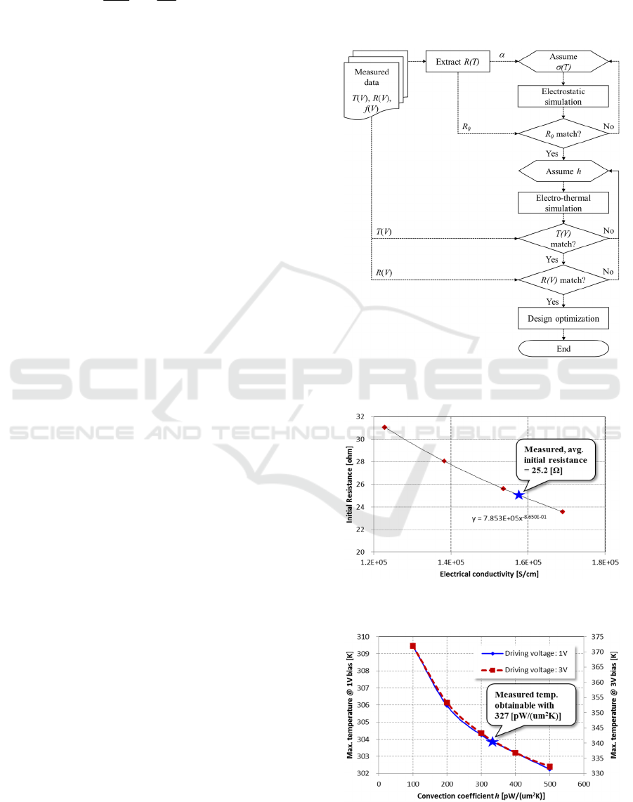
3.1 Parameter Definitions
In order to analyse the thermal stability of the micro
scanner accurately, it’s required to define all the
related parameters correctly. Based on the measured
resistance R(T), the temperature coefficient of
resistance
was calculated as 0.0086 /K. The other
parameter of the electric conductivity
is necessary
but it’s impossible to be analytically calculated due
to the geometric complexity. Thus parametric
numerical simulation on the electroplated Cu coil
was required to get the best-fitted value of the
conductivity. Figure 4 showed the fitted result of
1.5710
5
S/cm. Lee et al., (2003) reported electric
conductivity of the electroplated Cu as 1.5910
5
S/cm, which matched well with the fitted result.
Another parameter of convection coefficient h
was also fitted to the simulation results as shown in
Figure 5. In order to increase the fitting accuracy,
two sets of the measured temperature with 1V and
3V driving voltage, respectively, were used. The
resulting h of 327 pW/(um
2
K) was obtained.
Experimental verification on the required simulation
parameters of
,
, and h guaranteed the following
simulation results to be reliable.
Figure 3: Flow chart related with thermal stability
simulation procedures.
Figure 4: Fitting the electric conductivity based on the
measured result.
Figure 5: Determining the convection coefficient.
SIMULTECH 2016 - 6th International Conference on Simulation and Modeling Methodologies, Technologies and Applications
86
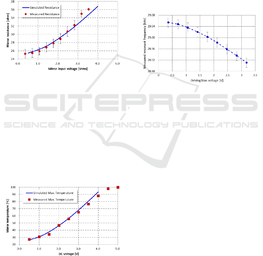
3.2 Simulation Results Verification
Fully-coupled electro-thermo-mechanical simulation
revealed the thermal stability issue of the micro
scanner. First of all, Joule heating caused by the
applied bias voltage increased the device
temperature as shown in Figure 6 where the
simulation results matched well with the measured
except the high bias region. Here the measured
temperature was obtained with thermal image
camera while changing the applied DC bias voltage.
Figure 6: Verification of the temperature change as a
function of the applied bias voltage.
The temperature increase changes the coil
resistance and vice versa. The coil resistance and the
following resonant frequency were measured with a
voltage-follower circuit connected to oscilloscope,
which requires AC bias voltage. Increasing the bias
voltage more than 4 V
rms
made the micro scanner
operation unstable, which matched with the high
bias region showing the saturated behaviour in
Figure 6. Hereafter the bias voltage was limited to
be lower than 4 V
rms
. The resistance variation caused
by the increased temperature were well captured by
the electro-thermal simulations as summarized in
Figure 7.
Figure 7: Verification of the resistance change as a
function of the applied bias voltage.
When a constant voltage is applied, the
temperature-induced increase in the coil resistance
reduces the current flowing, which decreases the
driving mechanical torque as described in Equation
(1). Then the decreased torque causes the reduction
in mirror rotation
as shown in Equation (5). To
avoid such a performance degradation, the
temperature of the device should be controlled
within the allowable range.
Considering the increases in temperature and
resistance shown in Figure 6 and 7, respectively, the
driving voltage should be limited not to exceed 4 V
because severe temperature increase in the
electroplated coil may damage the coil permanently.
Figure 8: Measured resonant frequency shift due to the
applied bias voltage.
Another important effect of the temperature
increase is the resonant frequency shift as shown in
Figure 8, which was caused by thermal expansions
in the device geometry and Young’s modulus
change. As the presented micro scanner amplifies its
rotation angle by driven at resonance, frequency
shift means that the change of operation point and
thus additional control algorithm such as phase-
locked loop (PLL) is required. The resonant
frequency shift is unavoidable but it should be
minimized because an abrupt shift makes the
controller more complex.
Related with the resonant frequency shift, it was
possible to extract dominant parameters such as coil
dimension, coil resistance, and heat dissipation
structure based on the previous multi-physics
simulations. Thus the proposed thermal stability
simulation procedure can be utilized for the design
optimization of the micro scanner.
4 CONCLUSIONS
In order to analyse the complex thermal stability
issue of MEMS micro scanner, multi-physics
simulation procedure was proposed. As the MEMS
Thermal Stability Simulation of MEMS Micro Scanner - Multi-physics Simulations Coupled with Experimental Verifications
87

micro scanner amplifies its scanning angle by driven
at resonance, it’s important to maintain the resonant
frequency stable although the increased device
temperature caused by Joule heating would change
the resonance. The proposed simulation procedure
calculated the voltage-induced temperature increase
accurately and revealed the dominant parameters
related with the thermal stability of the micro
scanner. Those results were proven by comparing to
the measured experimental data. It’s expected the
established procedure to contribute to the successful
commercialization of MEMS micro scanner by
increasing its thermal stability.
ACKNOWLEDGEMENTS
This work was supported by the Industrial
Technology Innovation Program (No.10047785)
funded by the Ministry of Trade, Industry & Energy
(MI, Korea).
REFERENCES
Bourgeois, C, Steinsland, E, Blanc, N and de Rooij, NF
1997, ‘Design of resonators for the determination of
the temperature coefficients of elastic constants of
monocrystalline silicon’, Proc. IEEE Int. Frequency
Control Symp., pp. 791-799.
Cho, AR, Han, A, Ju, S, Jeong, H, Park, JH, Kim, I, Bu,
JU and Ji, CH 2015, ‘Electromagnetic biaxial
microscanner with mechanical amplification at
resonance’, Optics Express 23(13), pp. 16792-16802.
CoventorWare
TM
2015, Coventor, Inc. Available from:
http://www.coventor.com/mems-solutions/products/
coventorware/. [5 March 2016].
Davis, WO, Sprague, R and Miller, J 2008, ‘MEMS-based
pico projector display’, IEEE/LEOS International
Conference on Optical MEMs and Nanophotonics, pp.
31-32.
Holmström, STS, Baran, U and Urey, H 2014, ‘MEMS
laser scanners: A review’, J. MEMS 23(2), pp. 259-
275.
Ji, CH, Choi, M, Kim, SC, Song, KC, Bu, JU and Nam, HJ
2007, ‘Electromagnetic two-dimensional scanner
using radial magnetic field’, J. MEMS 16(4), pp. 989-
996.
Kurth, S, Kaufmann, C, Hahn, R, Mehner, J, Dötzel, W
and Gessner, T 2007, ‘Performance and reliability test
of MEMS scanners’, Proc. of SPIE Vol. 6463, pp.
64630H-1-12.
Lee, H, Kwon, D, Park, H, Kim, HW, Lee, C and Lee, J
2003, ‘Rapid thermal annealing treatment of
electroplated Cu films’, J. Korea Phys. Soc. 43(5), pp.
841-846.
Moss, R, Yuan, P, Bai, X, Quesada, E and Sudharsanan, R
2012, ‘Low-cost compact MEMS scanning LADAR
system for robotic applications’, Proc. of SPIE Vol.
8379, pp. 837903-1-9.
Pengwang, E, Rabenorosoa, K, Rakotondrabe, M and
Andreff, N 2016, ‘Scanning micromirror platform
based on MEMS technology for medical application’,
Micromachines 7(2), pp. 24-52.
Saeedi, E, Miao, X and Amirparviz, B 2014, Whole image
scanning mirror display system, US Patent
8,817,379B2.
Strathman, M, Liu, Y, Keeler, EG, Song, M, Baran, U, Xi,
J, Sun, MT, Wang, R, Li, X and Lin, LY 2015,
‘MEMS scanning micromirror for optical coherence
tomography’, Biomedical Optics Express 6(1), pp.
211-224.
Varona, J, Tecpoyotl-Torres, M and Hmoui, AA 2007,
‘Modelling of MEMS thermal actuation with external
heat source’, Electronics, Robotics and Automotive
Mechanics Conf., pp. 591-596.
Zhang, XC, Myers, EB, Sader, JE and Roukes, ML 2013,
‘Nanomechanical torsional resonators for frequency-
shift infrared thermal sensing’, Nano Lett. 13(4), pp.
1528-1534.
SIMULTECH 2016 - 6th International Conference on Simulation and Modeling Methodologies, Technologies and Applications
88
