
Robust Registration Method of 3D Point Cloud Data
Sungho Suh, Hansang Cho and Donglok Kim
Samsung Electro-Mechanics, 150 Maeyoung-ro, Suwon, Korea
Keywords:
Point Cloud, 3D Affine Transformation, Height Map Matching.
Abstract:
3D point cloud data is used for 3D model acquisition, geometry processing and 3D inspection. Registration of
3D point cloud data is crucial for each field. The difference between 2D image registration and 3D point cloud
registration is that the latter requires several things to be considered: translation on each plane, rotation, tilt
and etc. This paper describes a method of registering 3D point cloud data with noise. The relationship between
the two sets of 3D point cloud data can be obtained by Affine transformation. In order to calculate 3D Affine
transformation matrix, corresponding points are required. To find the corresponding points, we use the height
map which is projected from 3D point cloud data onto XY plane. We formulate the height map matching as a
cost function and estimate the corresponding points. To find the proper 3D Affine transformation matrix, we
formulate a cost function which uses the relationship of the corresponding points. Also the proper 3D Affine
transformation matrix can be calculated by minimizing the cost function. The experimental results show that
the proposed method can be applied to various objects and gives better performance than the previous work.
1 INTRODUCTION
The method of image registration is to find a corre-
spondence between the original reference image and
the target image. It is used for various pattern recog-
nition, image processing and machine vision tasks
including object tracking (Comaniciu et al., 2003),
object recognition (Belongie et al., 2002), occlusion
handling (Nguyen and Smeulders, 2004), industrial
inspection (Rau and Wu, 2005) (Chena et al., 2009),
etc. And the method of image registration is also used
for 3D model acquisition, geometry processing and
3D inspection. Especially, we consider the registra-
tion between CAD data and the input data, or two in-
put data sets which are provided as 3D point cloud
data. For 3D scanning, the data inputs are acquired
as point cloud data. The acquired data as 3D point
cloud data are shown in Figure 1. There is a problem
in aligning the input data as point cloud data to the
given model.
The difference between 2D image registration and
3D point cloud registration is that the latter requires
several things to be considered: translation on every
plane, rotation, tilt, etc. The relationship between two
3D point cloud data sets can be obtained by Affine
transformation. If the Affine transformation matrix
between 3D point cloud data sets is obtained, 3D
point cloud data registration can be performed.
There are several popular methods for aligning
two point cloud data sets. Some of the most general
methods for registration are Iterative Closest Point al-
gorithm (P.J.Besl and McKay, 1992) (Y. and G, 1991)
and its variants (Rusinkiewicz and Levoy, 2001).
These methods start with two point cloud data sets
and refine the transformation between corresponding
points iteratively. One of them uses Eucledian dis-
tance for measuring the point-to-point distance. This
method converges slowly for input point cloud and
the given. Another metric uses the point to plane dis-
tance. When the initial position is close to the given
model and the input data has low noise, it is fast to
converge for the given model. However, when the
initial position is far from the given model or when
the input data is noisy, it cannot find the position. Be-
sides, many enhanced methods of the IterativeClosest
Point algorithm propose different error metrics and
point selection methods. (G. et al., 1992) (Fitzgib-
bon, 2003) (Gelfand et al., 2003) (Jost et al., 2003)
(Mitra et al., 2004) However, all the methods are slow
because of using iterative computation and they are
not robust to noise.
In order to solve the problems, we propose a ro-
bust registration method of 3D point cloud data. Our
method does not use iterative computation and it can
find a registration position of two point cloud data sets
with noise. To obtain 3D Affine transformation ma-
trix, corresponding points among two point cloud data
sets need to be found. To find corresponding points,
630
Suh, S., Cho, H. and Kim, D.
Robust Registration Method of 3D Point Cloud Data.
DOI: 10.5220/0005750606300637
In Proceedings of the 5th International Conference on Pattern Recognition Applications and Methods (ICPRAM 2016), pages 630-637
ISBN: 978-989-758-173-1
Copyright
c
2016 by SCITEPRESS – Science and Technology Publications, Lda. All rights reserved

Figure 1: Display 3D point cloud.
we use the height map which is projected from 3D
point cloud data onto XY plane. The height map has
pixel intensity from the height value of each point.
The height map is shown in Figure 2. The net pattern
in Figure 2 is caused by the region without point cloud
data. Some of the points can be missed and have noise
when the point cloud data is obtained by a scanning
machine. We need to consider the missed points when
we match two height maps which are projected from
two 3D point cloud data sets. If the two height maps
are matched, corresponding points can be estimated.
To match two height maps, the previous work (Suh
and Cho, 2015) proposed a 2D height map match-
ing method by calculating 2D Affine transformation
matrix, but it can especially be applied to the HDD
stamped base inspection (Park et al., 2013). As one of
the features of the HDD stamped base, there are mul-
tiple circles on the base. To calculate the 2D Affine
transformation matrix, it uses circle fitting for cor-
responding points between two height maps. But it
needs the corresponding points of more than three.
In other words, it cannot be applied to other objects
which do not have any features like circle or have cir-
cles less than three.
In this paper, we propose a cost function, which
consists of the difference between the intensities of
two height maps, for matching two height maps. The
corresponding points on the 3D coordinate can be ob-
tained by minimizing the cost function. By using
such points, we propose a method designed to achieve
3D Affine transformation matrix. To find the proper
3D Affine transformation matrix, we formulate a cost
function which uses the relationship of correspond-
ing points. Also the proper 3D Affine transformation
matrix can be calculated by minimizing the cost func-
tion. Then the two 3D point cloud data sets can be
matched.
The rest of this paper is organized as follows. The
details of matching two height maps and 3D regis-
tration of 3D point cloud data sets are proposed in
Section2. In Section 3, the experimental results are
presented. The experiments are performed for three
objects including HDD stamped base. The paper con-
cludes in Section 4 with description of our future
work.
2 REGISTRATION OF 3D POINT
CLOUD DATA SETS
In this section, we first match two height maps by the
proposed cost function. And we propose 3D regis-
tration method of point cloud data sets based on the
result of matching two height maps.
2.1 Matching Two Height Maps on
XY-plane
To obtain a 3D Affine transformation matrix between
two 3D point cloud data sets, finding corresponding
points is needed. First, we express two 3D point cloud
sets as two height maps on XY-plane. It means that
the resolution is expressed as the distance between
Robust Registration Method of 3D Point Cloud Data
631

Figure 2: Height maps of 3D point cloud on XY-plane.
x and y points and each pixel value has the height
value on Z-axis. There can be errors in translation,
scale and rotation errors between those two 2D height
maps. The height maps are shown in Figure 2.
We assume that pixel intensities of two height
maps, which are height values, have translation and
scale errors. We can formulate a cost function as a
sum of difference between two height maps.
min
(d
x
,d
y
)
∑
(x,y)
[αz(x+ d
x
,y+ d
y
) + z
0
− w(x,y)]
2
(1)
where d
x
,d
y
are the translation offsets between the
two height maps, α is a scale value, z,w are pixel
intensities of target and input height maps, and z
0
is
a translation offset of height. If the translation off-
sets which minimize (1) are calculated, correspond-
ing points between two 3D point cloud data sets can
be obtained. Furthermore, we assign several template
images on the height map and calculate the translation
offsets for each template image in order to reduce ef-
fects of rotation and computation. We assume for re-
ducing the number of variables that
z
0
= ˜w− α˜z (2)
where ˜w, ˜z are average pixel intensities of two height
maps. We can rewrite (1) by applying (2).
min
(d
x
,d
y
)
[
∑
(x,y)
{α(z(x+ d
x
,y+ d
y
) − ˜z) − (w(x,y) − ˜w)}
2
]
(3)
(3) can be expanded as follow.
min
(d
x
,d
y
)
[
∑
(x,y)
[α
2
(z(x+ d
x
,y+ d
y
) − ˜z)
2
− 2α(z(x+ d
x
,y+ d
y
) − ˜z)(w(x,y)− ˜w)
+ (w(x,y) − ˜w)
2
]]
(4)
We define the total number of pixels as N, then (4)
can be rewritten as follow.
min
(d
x
,d
y
)
[Nα
2
σ
2
z
− 2Nασ
zw
+ Nσ
2
w
]
(5)
where σ is standard deviation. To simplify the equa-
tion, we assume α =
σ
2
zw
σ
2
z
and express (5) as
min
(d
x
,d
y
)
Nσ
2
w
(1−
σ
2
zw
σ
2
w
σ
2
z
) (6)
In (6), N and σ
2
w
can be removed because they are
constant values. Therefore, (6) can be expressed as
follow.
max
(d
x
,d
y
)
σ
2
zw
σ
2
w
σ
2
z
(7)
Through (7), translation offset of each template image
can be obtained and the corresponding points between
3D points also can be estimated by matching those
two height maps.
2.2 3D Registration of Point Cloud Data
Sets
If the corresponding 3D points between the two point
cloud data sets are given by the method mentioned in
the previous subsection, the corresponding relation is
formulated as follow.
u
v
w
=
t
11
t
12
t
13
t
21
t
22
t
23
t
31
t
32
t
33
x
y
z
+
t
14
t
24
t
34
(8)
where (u,v,w) is the coordinate of the target data,
(x,y,z) is the corresponding point coordinate on input
data to the target data. To obtain unknown compo-
nents of the Affine transformation matrix above, we
propose a cost function as follows.
min
T
∑
k
[(t
11
x
k
+ t
12
y
k
+ t
13
z
k
+ t
14
− u
k
)
2
+(t
21
x
k
+ t
22
y
k
+ t
23
z
k
+ t
24
− v
k
)
2
+(t
31
x
k
+ t
32
y
k
+ t
33
z
k
+ t
34
− w
k
)
2
]
(9)
where T is the 3D Affine transformation matrix com-
posed of t, and k is the index of the corresponding
point.
ICPRAM 2016 - International Conference on Pattern Recognition Applications and Methods
632

As shown above, we obtain the components of
the 3D Affine transformation matrix which minimizes
the difference between the point on the two 3D point
cloud data sets after applying 3D Affine transforma-
tion. In order to reduce the number of variables,
t
14
= ˜u− ˜xt
11
− ˜yt
12
− ˜zt
13
t
24
= ˜v− ˜xt
21
− ˜yt
22
− ˜zt
23
t
34
= ˜w− ˜xt
31
− ˜yt
32
− ˜zt
33
(10)
where ˜x, ˜y, ˜z, ˜u, ˜v, ˜w are the average of each compo-
nent. By using (10), (9) can be rewritten as
min
T
∑
k
[(t
11
(x
k
− ˜x) + t
12
(y
k
− ˜y) + t
13
(z
k
− ˜z)
−(u
k
− ˜u))
2
+ (t
21
(x
k
− ˜x) + t
22
(y
k
− ˜y)
+t
23
(z
k
− ˜z) − (v
k
− ˜v))
2
+ (t
31
(x
k
− ˜x)
+t
32
(y
k
− ˜y) + t
33
(z
k
− ˜z) − (w
k
− ˜w))
2
]
(11)
Thus, we can rewrite (11) as
F = min
T
∑
k
[(t
2
11
σ
2
x
+ t
2
12
σ
2
y
+ t
2
13
σ
2
z
+ 2t
11
t
12
σ
xy
+ 2t
11
t
13
σ
xz
+ 2t
12
t
13
σ
yz
− 2t
11
σ
xu
] − 2t
12
σ
yu
− 2t
13
σ
zu
) + (t
2
21
σ
2
x
+ t
2
22
σ
2
y
+ t
2
23
σ
2
z
+ σ
2
v
+ 2t
21
t
22
σ
xy
+ 2t
21
t
23
σ
xz
+ 2t
22
t
23
σ
yz
− 2t
21
σ
xv
− 2t
22
σ
yz
− 2t
23
σ
zv
) + (t
2
31
σ
2
x
+ t
2
32
σ
2
y
+ t
2
33
σ
2
z
+ σ
2
w
+ 2t
31
t
32
σ
xy
+ 2t
31
t
33
σ
xz
+ 2t
32
t
33
σ
yz
− 2t
31
σ
zw
− 2t
32
σ
yw
− 2t
33
σ
zw
]
(12)
where σ is the standard deviation of each component.
All standard deviations can be calculated from the tar-
get and input data.
To find the value of t
ij
that minimizes the cost
function (12), we set ∂F/∂t
ij
= 0. And all of the equa-
tions can be written as
t
11
σ
2
x
+ t
12
σ
xy
+ t
13
σ
xz
− σ
xu
= 0,
t
12
σ
2
y
+ t
11
σ
xy
+ t
13
σ
yz
− σ
yu
= 0,
t
13
σ
2
z
+ t
11
σ
xz
+ t
12
σ
yz
− σ
zu
= 0,
t
21
σ
2
x
+ t
22
σ
xy
+ t
23
σ
xz
− σ
xv
= 0,
t
22
σ
2
y
+ t
21
σ
xy
+ t
23
σ
yz
− σ
yv
= 0,
t
23
σ
2
z
+ t
21
σ
xz
+ t
22
σ
yz
− σ
zv
= 0,
t
31
σ
2
x
+ t
32
σ
xy
+ t
33
σ
xz
− σ
xw
= 0,
t
32
σ
2
y
+ t
31
σ
xy
+ t
33
σ
yz
− σ
yw
= 0,
t
33
σ
2
z
+ t
31
σ
xz
+ t
32
σ
yz
− σ
zw
= 0
(13)
The system equation problem can be represented in
the following matrix form:
σ
2
x
σ
xy
σ
xz
σ
xy
σ
2
y
σ
yz
σ
xz
σ
yz
σ
2
z
t
11
t
12
t
13
=
σ
xu
σ
yu
σ
zu
σ
2
x
σ
xy
σ
xz
σ
xy
σ
2
y
σ
yz
σ
xz
σ
yz
σ
2
z
t
21
t
22
t
23
=
σ
xv
σ
yv
σ
zv
σ
2
x
σ
xy
σ
xz
σ
xy
σ
2
y
σ
yz
σ
xz
σ
yz
σ
2
z
t
31
t
32
t
33
=
σ
xw
σ
yw
σ
zw
(14)
Here all σ are known parameters. Thus, using (10)
and (14), we can obtain all elements of the 3D Affine
transformation. The input 3D point cloud data can be
aligned to the target 3D point cloud data after apply-
ing the obtained the 3D Affine transformation to all of
the points on the input data.
3 EXPERIMENTAL RESULT
In this section, we evaluate the performance of the
proposed method with artificially transformed data
and real data of HDD stamped base. And we com-
pare the results of the proposed method to the results
of the previous work. Additionally, we evaluate the
performance for the other objects, not HDD stamped
base, without circle patterns.
In our experiment, Coherix S150 Holographic
Sensor (Christman et al., 2012) is used for acquiring
3D point cloud data. We acquire the 3D point cloud
data by the resolution as 0.08 mm. First, we transform
the CAD data of HDD stamped base to several cases.
1) 1 degree rotated on all planes, 2) 2 degrees rotated
on all planes, 3) 3 degrees rotated on all planes, 4)
transformed by random transformation matrix. Fur-
thermore, we acquire the 3D point cloud data of five
HDD stamped bases. Using those data sets, we com-
pare the previous work (Suh and Cho, 2015) and the
proposed method. The results are shown in Figure 3,
4, 5, 6, 7. First left images are the height maps of
the original CAD, second left images are input data
which are the height maps of the artificially trans-
formed data and scanned data. Third ones and last
ones show the example height maps of the result by
the previous work (Suh and Cho, 2015) and the pro-
posed method.
In the figures, the results by the proposed method
are changed to the height maps of the CAD. And the
input data which have rotation and translation on XY-
plane are also transformed to the height maps of the
CAD. Comparing the results of the proposed method
and the results of the previous work which uses the
Robust Registration Method of 3D Point Cloud Data
633

(a) CAD. (b) Input data. (c) By the method in (Suh and
Cho, 2015).
(d) By the proposed method.
Figure 3: Registration for the data rotated 1 degree on all planes.
(a) CAD. (b) Input data. (c) By the method in (Suh and
Cho, 2015).
(d) By the proposed method.
Figure 4: Registration for the data rotated 2 degree on all planes.
(a) CAD. (b) Input data. (c) By the method in (Suh and
Cho, 2015).
(d) By the proposed method.
Figure 5: Registration for the data rotated 3 degree on all planes.
(a) CAD. (b) Input data. (c) By the method in (Suh and
Cho, 2015).
(d) By the proposed method.
Figure 6: Registration for the data rotated by random transformation matrix.
(a) CAD. (b) Input data. (c) By the method in (Suh and
Cho, 2015).
(d) By the proposed method.
Figure 7: Registration for the real data of HDD stamped base.
ICPRAM 2016 - International Conference on Pattern Recognition Applications and Methods
634

Table 1: Average height differences for HDD stamped base data sets.
By input data By the previous work By the proposed method
1
◦
rotated 0.2149 0.0039 0.0155
2
◦
rotated 0.3647 0.0088 0.0162
3
◦
rotated 0.4690 0.0229 0.0159
transformed randomly 0.5721 0.1202 0.0097
Real data 1.1145 0.1701 0.0953
(a) Target data (b) Input data. (c) By the proposed method.
Figure 8: Registration for Pin.
center points of circle feature, both methods make the
input data transformed to the CAD data as well. To
measure the defined error, we compare height differ-
ences between the original CAD data and the meth-
ods. The height differences are shown in Table 1.
Table 1 shows the averages of height difference
for HDD stamped base data sets. The differences are
represented as mm. Both the previous work and the
proposed method make the input data sets converged
to the CAD data, because the averages are close to
0. And the results of the proposed method are similar
to the results of the previous work. The result of the
proposed method for the data randomly transformed
reduces errors dramatically compared to the result of
the previous work. And using the input data which
has bigger error, the proposed method gives better
performance than the previous work. In addition, the
resolution of the 3D point cloud data is 0,08mm in the
experiment as mentioned earlier. The height errors
of the proposed method are almost less than 0.08. It
means that the error is within 1 pixel and it is within
error range. However, the previous method shows the
errors for the data transformed randomly and the real
data are much larger than 0.08. Therefore, we claim
that the proposed method allows the 3D point cloud
data of HDD stamp base to be aligned to the CAD
data more accurately than the previous method.
We also acquire the 3D point cloud data sets of
the other objects and show the results of the proposed
Table 2: Average height differences for metal pin and CPU
fan.
Input data By the Proposed method
PIN 1.3143 0.0174
FAN 1.2364 0.0732
method with the data sets. Figure 8 and 9 show the
height map of the 3D point cloud data for rib cage
shaped metal object and CPU fan. In the figures, even
though there are big differences between the target
and input data sets, the results of the proposed method
show that the proposed method makes the input data
sets transform to the target data sets as well. As same
as Table 1, Table 2 shows the average height differ-
ences for the two objects.
The method in (Suh and Cho, 2015) cannot be ap-
plied to the objects because the objects do not have
enough circle features for circle fitting. Also, since
the resolution is 0.08mm for the data sets and the
height errors by the proposed method in Table 2 are
less than 0.08mm, the proposed method can perform
the registration of 3D point cloud data for various ob-
jects properly.
Robust Registration Method of 3D Point Cloud Data
635
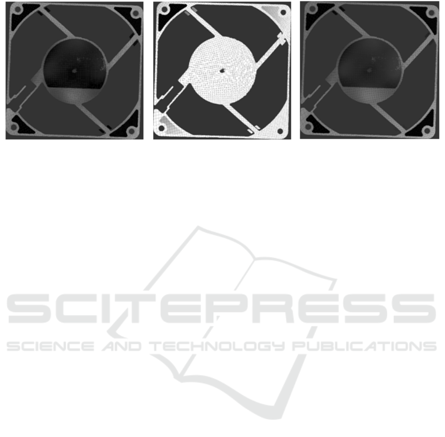
(a) Target data. (b) Input data. (c) By the method in (Suh and Cho, 2015).
Figure 9: Registration for Fan.
4 CONCLUSIONS
In this paper, a robust registration method has been
proposed for 3D point cloud data with noise. The
proposed method is robust to noise and do not use
iterative computation. The proposed method can ap-
ply for the objects without any circular features. The
proposed method generated the height map, whose
pixel intensity is represented as the height value of
the 3D point cloud data, and matched the two height
maps from two different 3D point cloud data sets. In
order to match the two height maps, we proposed a
cost function and found translation offsets for tem-
plate images. The corresponding points between the
two 3D point cloud data sets can be obtained from
the matched two height maps. We formulated another
cost function for calculating the components of 3D
Affinetransformationmatrix by using the correspond-
ing points from height map matching. We used 3D
point cloud data sets of HDD stamp base and the other
objects for a performance evaluation. The experiment
result showed that the proposed method gave better
performance than the previous work (Suh and Cho,
2015) for HDD stamp base and could be applied to
the other objects without circle features.
Since the experiment was performed for three dif-
ferent objects, we need to experiment more various
objects. Moreover,the performance of the height map
matching method can differ how to select the template
images. Therefore, further investigation is needed to
select proper template images automatically.
REFERENCES
Belongie, S., Malik, J., and Puzicha, J. (2002). Shape
matching and object recognition using shape contexts.
IEEE Transations on Pattern Analysis and Machine
Intelligence, 24(24):509 – 522.
Chena, C.-S., Yeha, C.-W., and Yin, P.-Y. (2009). A novel
Fourier descriptor based image alignment algorithm
for automatic optical inspection. Journal of Visual
Communication and Image Representation, 20:178–
189.
Christman, S., Doman, D., and Kamal, A. S. B. A. (2012).
Final report for a demonstration structure for a 3d
holographic sensor. University of Michigan ME450.
Comaniciu, D., Ramesh, V., and Meer, P. (2003). Kernel-
based object tracking. IEEE Transations on Pattern
Analysis and Machine Intelligence, 25(5):564 – 577.
Fitzgibbon, A. W. (2003). Robust registration of 2d and
3d point sets. Image and Vision Computing, 21:1145–
1153.
G., C., S., L., R., S., and L., B. (1992). From accurate range
imaging sensor calibration to accurate model-based 3d
object localization. IEEE Conference of Computer Vi-
sion and Pattern Recognition, pages 83–89.
Gelfand, N., Ikemoto, L., Rusinkiewicz, S., and Levoy, M.
(2003). Geometrically stable sampling for the icp al-
gorithm. 3-D Digital Imaging and Modeling, pages
260–267.
Jost, Timothee, and Hugli., H. (2003). A multi-resolution
icp with heuristic closest point search for fast and
robust 3d registration of range images. 3-D Digital
Imaging and Modeling, pages 427–433.
Mitra, N. J., Gelfand, N., Pottmann, H., and Guibas,
L. (2004). Registration of point cloud data from
a geometric optimization perspective. Eurograph-
ics/ACM SIGGRAPH symposium on Geometry pro-
cessing, pages 22–31.
Nguyen, H. T. and Smeulders, A. W. (2004). Fast Occluded
Object Tracking by a Robust Appearance Filter. IEEE
Transations on Pattern Analysis and Machine Intelli-
gence, 26(8):1099–1104.
Park, K.-S., Lee, H.-C., Kim, J.-H., Kim, S., Seo, J., Rhim,
Y., and Park, N.-C. (2013). Analysis on the character-
istics of stamped base for 2.5 in hdd. IEEE Transac-
tion on Magnetics, 49.
P.J.Besl and McKay, N. (1992). A method for registration
ICPRAM 2016 - International Conference on Pattern Recognition Applications and Methods
636

of 3-d shapes. IEEE Trans. Pattern Analysis and Ma-
chine Intelligence, 14:239–256.
Rau, H. and Wu, C.-H. (2005). Automatic optical inspec-
tion for detecting defects on printed circuit board inner
layers. The International Journal of Advanced Manu-
facturing Technology, 1(9-10).
Rusinkiewicz, S. and Levoy, M. (2001). Efficient variants
of the icp algorithm. International Conference on 3D
Digital Imaging and Modeling, pages 145–152.
Suh, S. and Cho, H. (2015). Registration of point cloud
data for hdd stamped base inspection. SPIE Optical
Engineering+ Applications. International Society for
Optics and Photonics, pages 95991P–95991P–10.
Y., C. and G, M. (1991). Object modeling by registration of
multiple range images. IEEE Conference on Robotics
and Automation.
Robust Registration Method of 3D Point Cloud Data
637
