
Angular Arrangement Optimization of the Support Racks of Gas
Turbine Engine to Reduce the Circumferential Unevenness
of Gas Flow
Grigorii M. Popov, Daria Kolmakova and Aleksandr O. Shklovets
Institute of Propulsion and Power Systems, Samara State Aerospace University (SSAU), Samara, Russian Federation
Keywords: Circumferential Distortion, Axial Compressor, Rotor Blades, Support Racks.
Abstract: This work is motivated by the necessity to reduce the effects of the flow circumferential distortion in the
flow passage of the aircraft gas turbine engine (GTE). During the presented research, another principal of
reduction of the flow circumferential distortion was chosen. Firstly, the variants of upgrading the existing
support racks were found. Secondly, the new design of support was offered. Both version of the support
design variation took into account the availability of technological and structural limitations associated with
the location of oil pipes, springs and others elements in the support racks. Investigations of modified design
showed that the support with altered racks provides a reduction of dynamic stresses by 20% at resonance
with the most dangerous harmonic, and the new design of support can give the decrease of 30%.
1 INTRODUCTION
Many problems that are currently faced by
researchers and engineers cannot be solved
analytically or require huge costs for the
experimental realization. Often, the only possibility
to carry out the express analysis of engineering
problems is a computer and mathematical
simulation. Progress in the development of
numerical methods significantly increased the
number of tasks available for analysis (Popov, et al.,
2014.). The obtained results based on these methods
are used in almost all fields of science and
technology.
The finite element method finds its most
important application in the design analysis. At the
same time, bridges, buildings, marine hulls, aircraft
components, machine parts, pistons, tools, i.e. any
engineering construction are understood under
“construction” in the design analysis.
Turbomachinery impellers are very critical parts
of gas turbine engines. The reliable engine operation
and flight safety of the aircraft depend on their
reliable operation of impellers to a large extent
(Shabliy and Cherniaev, 2014).
The possibility of appearance of variable
dynamic stresses in the impellers associated with the
action of the changing in time loads on it. One of the
main types of dangerous oscillations are forced.
Forced oscillations are due to the impact of
external forces on the object, time-varying, which do
not depend on dynamic behaviour of a vibrating
object and do not change under the assumption of
object non-deformable. In turbomachines these
forces associated with circumferential uniform of
flow incident on the rotating impeller. The
circumferential distortion is transformed into power
load that varies in time.
2 CALCULATION METHOD OF
FORCED OSCILLATIONS
Circumferential nonuniformity of the gas stream
flowing around the blades is the main source of
vibration excitation of the gas turbine engine rotor
wheels (RW). It appears in the form of
nonuniformity of the velocity and pressure fields in
the stream before and after the RW. Nonuniformity
leads to the fact that the gas load intensity in the
circumferential and radial directions is inconstant
around the circumference of the flow passage. The
integrated gas-dynamic force Q
g
changeable in value
acts on any of the blades during RW rotation.
383
M. Popov G., Kolmakova D. and O. Shklovets A..
Angular Arrangement Optimization of the Support Racks of Gas Turbine Engine to Reduce the Circumferential Unevenness of Gas Flow.
DOI: 10.5220/0005570403830388
In Proceedings of the 5th International Conference on Simulation and Modeling Methodologies, Technologies and Applications (SIMULTECH-2015),
pages 383-388
ISBN: 978-989-758-120-5
Copyright
c
2015 SCITEPRESS (Science and Technology Publications, Lda.)
Since the gas-dynamic force Q
g
is a periodic
value, i.e. Q
g
() = Q
g
(+2), it can be expanded in
a Fourier series:
∑
∙ cos
(1)
where Q
m
– the amplitude of the component
harmonic; m
e
– harmonic number;
– center angle,
γ
m
– phase shift along the circumference.
Expansion (1) allows presenting the gas load
having a complex distribution along the
circumference as a sum of component harmonics.
Each of them represents a succession of load waves
that fit around the circumference of flow passage.
For rotating impeller, any of the components in
(1) is exciting harmonic, which is the backward
running waves succession. The load rotates with an
angular velocity ω, which equal to the angular
velocity of RW. Thus, the circumferential gas flow
nonuniformity for rotor wheels is equivalent to an
effects of infinite set of exciting harmonics, each of
which represents a succession
e
m
of backward
running waves of load oscillates in time with
frequency f
e
= m
e
n
s
, where
To determine the dynamic stresses in the blade
airfoil, Ansys software was used. Gas dynamic load
force on the blades is determined in static CFD-
calculation. Using APDL programming language,
the program was written that imports the load
distribution from finite element model of blade row
in CFX to finite element model of the blade row in
Ansys Mechanical APDL. Then, the load is
decomposed in Fourier series at congruent nodes of
blades and is represented as a backward running
wave. Campbell diagram is used to determine the
most dangerous engine modes, and correspondingly,
the most dangerous harmonics. Dynamic stress
analysis is carried out only with the most dangerous
harmonic. This method is described in detail in
(Ermakov et al., 2014).
Damping in the system is defined on the basis of
experimental data as a viscous in material. Thus we
cannot state that this calculation method allows
evaluating the quantitative dynamic stresses in the
blade at the design stage. However, this method is
acceptable for qualitative assessment of changes of
dynamic stresses during the optimization.
3 IMPLEMENTATION OF
METHOD
Practical implementation of the method is discussed
in (Ermakov, Shklovets, Popov, Kolmakova, 2014).
The object of the investigation is fifth stage rotor
wheel blade of medium pressure compressor (IPC)
of GTE (Figure 1). Downstream the fifth stage of the
IPC, the middle GTE support is located.
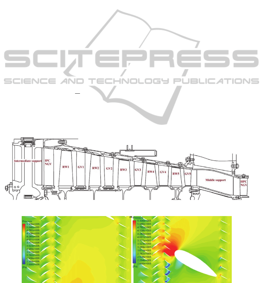
Figure 1: The diagram of the investigated compressor.
a) b)
Figure 2: Pressure fields between support rack (a) and close to racks (b).
SIMULTECH2015-5thInternationalConferenceonSimulationandModelingMethodologies,Technologiesand
Applications
384
Seven racks of different cross-sections are
unevenly distributed in the flow passage of support
casing. These racks cause the circumferential
variation of the gas flow in gas-turbine engine flow
passage, which leads to increased dynamic stresses
in the fifth rotor wheel blades, as a consequence, to
its breakage (Figure 2).
As the number of support racks is 7, the blade
was detuned from the dangerous seventh harmonic
at the design stage. The natural frequency of the RW
blade vibrations is selected so that the resonance is
possible with the eighth harmonic and higher.
Seventh harmonic is beyond the engine operating
conditions. Experimental research revealed the
destruction of the rotor blade of compressor stage at
resonance with the 12
th
harmonic.
On the basis of the above-described method of
calculation of blade forced oscillations, the
maximum alternating stresses were defined in the
fifth stage rotor blade of IPC reference design
operating in the conditions of gas flow
circumferential distortion.
To reduce the circumferential distortion of the
flow, stagger angles and pitch of fifth stage guide
vanes were changed to non-uniform around the
circumference of the rotor wheel (Figure 3). At the
same time, CFD-calculation qualitatively coincides
with the experiment.
As a result, the optimal variant of the design was
chosen, in which the amplitude of the dangerous
12th harmonic was reduced by 2 times, while the
number of changeable guide vane (GV) blades was
equal to 14 (total blade number is 76).
4 EFFECT OF SUPPORT DESIGN
ON CIRCUMFERENTIAL
DISTORTION
4.1 Changing Angular Location of
Support Racks
Technologically, changing the stagger angle of the
guide vane blade is challenging, so it was decided to
change the configuration of the support rack.
Therefore, the experimental variant of support with
13 racks instead of standard support with seven
racks was considered at the next stage of the
research (Figure 4). The experimental tests were
conducted by JSC "Kuznetsov" (Samara, Russia) –
the enterprise of aviation and space propulsion
engineering. (JSC "Kuznetsov", 2014).
It was revealed that the mean amplitude of
dangerous 12th harmonic decreased by 2 times in
the computational studies (experimental data
confirm this). The coincidence of obtained results
with experimental data confirms the adequacy of
computational models and techniques. There was a
significant decrease in the amplitudes of all
dangerous harmonics.
The rack thickness, in which the engine systems
are located, and their angular disposition were
changed in the 13-racks experimental support.
Therefore, such support cannot be applied at
modernized engine. Consequently, one of the
conditions was to keep unchanged the racks 1, 3, 4,
and 7 of standard 7-racks the support (Figure 4)
when optimizing the angular arrangement of racks.
For this, the optimization technique of the
angular position of support racks was developed.
Angular position of racks was represented as a
periodic function. Function was provided in the form
of discrete data array containing the nominal
pressure before each rack, which was equal to one.
The array contained 180 values; each value
corresponded to the angle of the circumferential
location of the rack. Then the function value was 0 if
there was no the rack and the value was 1 if there
was rack is. Changing the angular arrangement of
free racks, decrease of dangerous harmonics
amplitude can be achieved.
Figure 3: The algorithm of introduction of different
stagger angle and pitch.
Reduction in the amplitude of the 12
th
harmonic
was performed using optimization methods
implemented in the software package IOSO
(Egorov, Kretinin, Leshchenko, Kuptzov, 2002.).
The goal of optimization was to decrease the
amplitudes of 10
th
and 12
th
harmonics.
AngularArrangementOptimizationoftheSupportRacksofGasTurbineEnginetoReducetheCircumferential
UnevennessofGasFlow
385
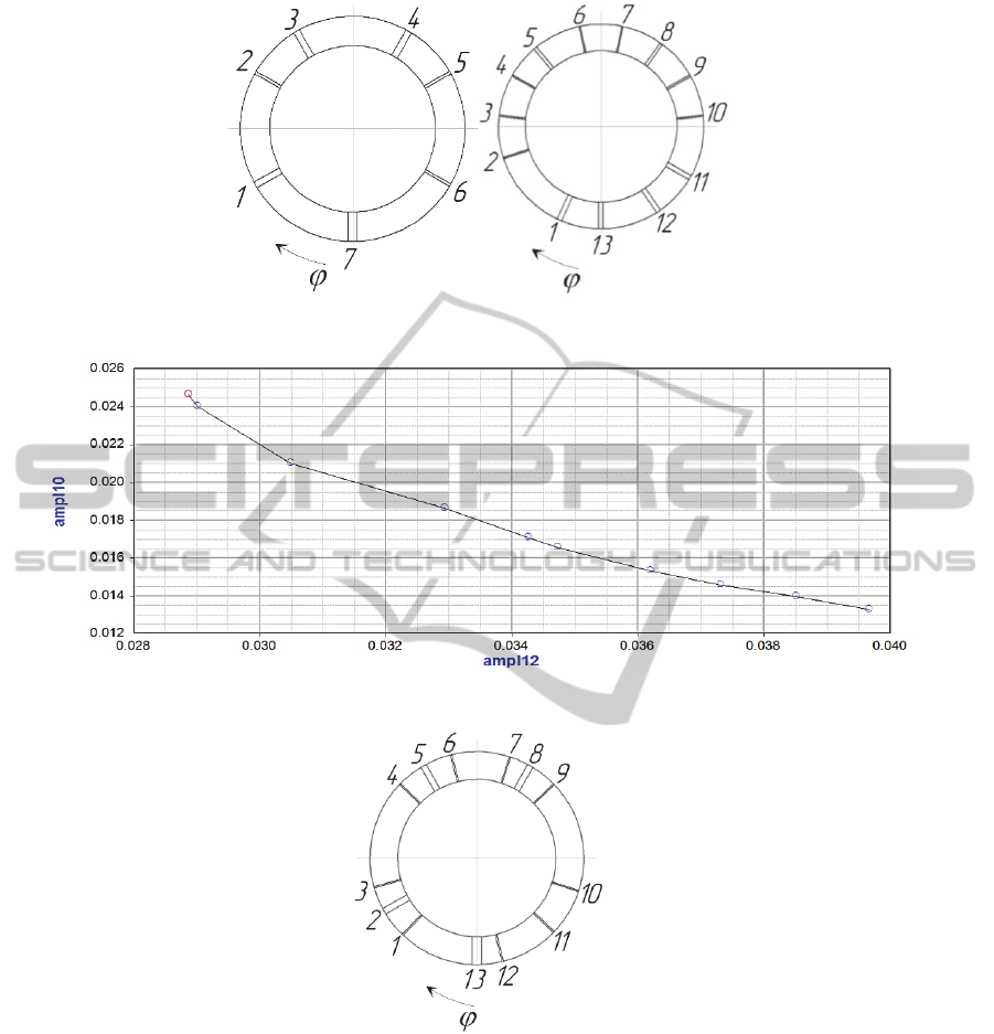
Figure 4: Scheme of standard 7-racks support and modified 13th-racks support.
Figure 5: The Pareto set of multicriteria optimization.
Figure 6: Location of support racks corresponding to the point of the Pareto set.
Consequently, the optimization criterion was the
amplitudes of 10
th
and 12
th
harmonics.
Angles of the 1, 3, 4, 6, 7, 9-12 racks were used
as variable parameters. In formulation of
optimization problem, the restrictions on the
amplitude values of 8, 9, 11 and 13 harmonics were
imposed. These restrictions were assigned so that the
amplitude values of these harmonics obviously did
not lead to the destruction of the blades.
During the optimization, the Pareto front was
obtained - the set of unimprovable solutions, a
compromise between the decrease in the amplitude
of 10
th
and 12
th
harmonics (Figure 5). A unique array
of angular location of 1, 3, 4, 6, 7, 9-12 racks
corresponded to each point of the Pareto set.
For further analysis, the leftmost point of Pareto
front was selected (Figure 5). This point corresponds
to the maximum possible reduction in the amplitude
of the 12
th
harmonic, as the most dangerous.
Location of the racks, shown in Figure 6,
corresponds to this point of the Pareto set.
SIMULTECH2015-5thInternationalConferenceonSimulationandModelingMethodologies,Technologiesand
Applications
386
4.2 Changing Position of Support
Racks Relative to Blades of
Upstream Guide Vane
There are experimental studies that prove that the
lattice, which is located in front of the cylinder,
streamlined by the flow, enhances the upstream
transmission of the high pressure zone (Saren,
1984).
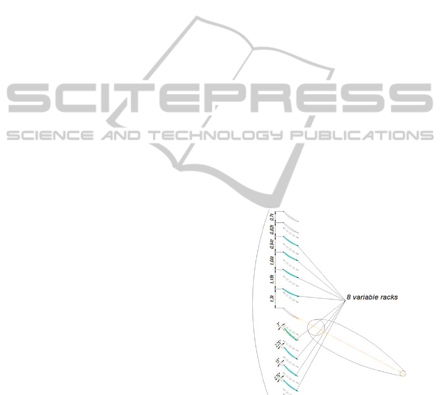
The results of that research allow us to offer an
additional way to reduce the dynamic stresses. It
represents a change in the form of support racks due
to remoteness of the leading edge of support racks
(cylinder) from the trailing edges of GV blades of
fifth stage (lattice). At the same time, the internal
cavities of racks remain unchanged for the
placement of engine systems (Figure 7) (Pechenin,
Bolotov, Rusanov, 2014).
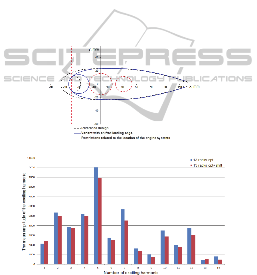
Figure 8 shows a comparison of the harmonic
amplitudes of the optimized 13-racks support
without shifting the leading edges and with shifted
leading edges of racks. Figure 9 shows a comparison
of harmonic amplitudes of the 7-racks support, the
reference design of 13-racks support (by JSC
“Kuznetsov”) and optimized 13-racks support with
shifted leading edges (by SSAU).
Thus, the implementation of optimized 13-racks
support with shifted leading edges reduces the
amplitude of the most dangerous harmonic in 1.8
times, while the position of four the support racks
with engine systems remains unchanged.
Figure 7: The algorithm of shift of the rack leading edge.
Figure 8: Mean amplitude of the exciting harmonics of the 13-racks support with and without shifted leading edges.
AngularArrangementOptimizationoftheSupportRacksofGasTurbineEnginetoReducetheCircumferential
UnevennessofGasFlow
387
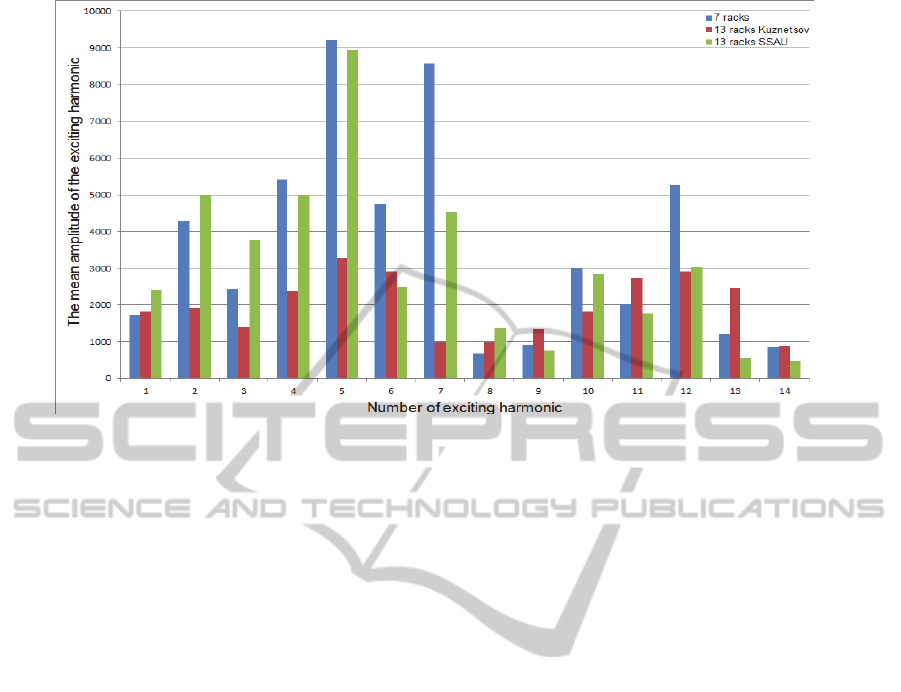
Figure 9: Mean amplitude of the exciting harmonics of the 7-racks support, reference 13-racks support (Kuznetsov) and
optimized 13-racks support with shifted leading edges (SSAU).
5 CONCLUSIONS
The high level of circumferential distortion of the
gas flow in aircraft engine is caused by many
factors. One of the major is the presence of support
racks in the flow passage.
Change in the angular position of support racks
allows redistributing and reducing the amplitude of
the exciting harmonics.
During the research, the optimization technology
of angular arrangement of support racks was
developed by the software IOSO due to the discrete
representation of a response from the rack.
This allowed obtaining the optimum racks
location of 13-racks support, providing decrease in
the amplitude of 12
th
harmonic in 2 times.
Furthermore, the variant of variable dynamic
stresses reduction was proposed due to shape
correction of support racks (shift of the rack leading
edges relative to the trailing edges of GV blades
located in front of the support).
This method provided a decrease in the
amplitude of the 12
th
harmonic in 1.8 times.
ACKNOWLEDGEMENTS
This work was supported by the Ministry of
Education and Science of the Russian Federation in
execution of the order №218 from 09.04.2010
(theme code 2013-218-04-4777).
REFERENCES
Popov, G., Baturin, O., Kolmakova, D. Krivcov, A., 2014.
Improvement Results of TK-32 turbocompressor
turbine with gas-dynamics and strength CAE-systems.
In International J. of Engineering and Technology
Vol. 6, pp. 2297-03.
Shabliy, L.S., Cherniaev, A.V., 2014. Optimization of
compressor blade geometry for efficiency and pressure
ratio under strength constraint. In Proc. of ASME 2014
Gas Turbine India Conference, GTINDIA 2014,
GTINDIA2014-8132.
Ermakov, A., Shklovets, A., Popov, G., Kolmakova, D.,
2014. Investigation of the effect of the gas turbine
compressor supports on gas flow circumferential
nonuniformity. In Research J.l of Applied Sciences,
vol. 9, pp. 684-690.
JSC "Kuznetsov", Accessed October 10, 2014.
http://www.kuznetsov-motors.ru/en.
Egorov, I., Kretinin, G., Leshchenko, I., Kuptzov, S.,
2002. IOSO Optimisation Toolkit - Novel Software to
Create Better Design. In Proc. 9th AIAA/ISSMO
Symposium on Multidisciplinary Analysis and
Optimisation.
Saren, V., 1984. Flow around irregular lattice of plates
placed in front of the cylinder, Technical Report,
Central Institute of Aviation Motors, Moscow.
Pechenin, V.A., Bolotov, M.A., Rusanov, N.V., 2014.
Method of evaluation of profile form and shaped
surfaces with application of wavelets. In Research
Journal of Applied Sciences, Vol. 9 (11), pp. 820-824.
SIMULTECH2015-5thInternationalConferenceonSimulationandModelingMethodologies,Technologiesand
Applications
388
