
Database Evolution for Software Product Lines
Kai Herrmann
1
, Jan Reimann
2
, Hannes Voigt
1
, Birgit Demuth
2
, Stefan Fromm
3
, Robert Stelzmann
4
and Wolfgang Lehner
1
1
Database Technology Group, Technische Universität Dresden, Germany
2
Software Technology Group, Technische Universität Dresden, Germany
3
Dresden-Informatik GmbH, Dresden, Germany
4
iSAX GmbH & Co. KG, Dresden, Germany
Keywords:
Database, Software Product Lines, Evolution.
Abstract:
Software product lines (SPLs) allow creating a multitude of individual but similar products based on one
common software model. Software components can be developed independently and new products can be
generated easily. Inevitably, software evolves, a new version has to be deployed, and the data already existing
in the database has to be transformed accordingly. As independently developed components are compiled
into an individual SPL product, the local evolution script of every involved component has to be weaved into
a single global database evolution script for the product. In this paper, we report on the database evolution
toolkit DAVE in the context of an industry project. DAVE solves the weaving problem and provides a feasible
solution for database evolution in SPLs.
1 INTRODUCTION
With the directives 2008/43/EG and 2012/4/EU, the
European Commission made the tracking of explo-
sives mandatory in the European Union (EU) from 5
th
April 2015 on. All explosives for civil use, including
detonators, primers, boosters, cords, etc., have to be
tracked during their whole life cycle in the EU. This
has to be applied from the manufacturing location or
import into the EU towards the end user. For instance,
a company producing black powder has to attach a
unique identifier to every unit it produces. A freight
shipping company transfers such units of black pow-
der to distributors. Another manufacturer buys a unit
of black powder to make primers, each getting a new
identifier. The life cycle of the primer and the black
powder continues to include further dealers and carri-
ers until they are eventually put in use in e.g. a small
stone quarry. All participants in the life cycle of ex-
plosives are required to store the tracking information
of each item as it passes their domain. The track-
ing information includes the identifier of each item
together with the time stamp and partner of the in-
coming and outgoing events. In the research-oriented
industry project euroTRACKex (http://www.tt-e.eu)
(eTe), we develop a demonstrator of a tracking soft-
ware for explosives that will help companies to fulfill
their obligations.
Independent of the application field, life cycle
tracking confronts the involvedparties with liabilities,
which can only be handled feasibly with IT support.
All participants need basically the same software to
track specific goods. However, their detailed require-
ments vary considerably. Participants (small business
to large enterprise, producer to dealer to carrier to
consumer) significantly differ regarding their finan-
cial constraints, followed processes, implemented IT
landscapes, and national legislations.
With such a diverse customer base, it is econom-
ically infeasible to try designing and implementing
one software product that satisfies the requirements
of all potential customers. Likewise, it is uncompeti-
tive to implement a specialized solution for each cus-
tomer. Software product line engineering is a long
studied but rarely implemented technique to gain the
necessary flexibility in software development for han-
dling a very diverse customer base. An SPL is defined
by a common software model, which decouples the
development from the deployment. That allows dis-
tributing the development of the software components
among multiple parties. Ultimately, concrete software
products can be generated from the SPL according to
an individual configuration for each customer. Soft-
ware technology research provides tooling and meth-
125
Herrmann K., Reimann J., Voigt H., Demuth B., Fromm S., Stelzmann R. and Lehner W..
Database Evolution for Software Product Lines.
DOI: 10.5220/0005484101250133
In Proceedings of 4th International Conference on Data Management Technologies and Applications (DATA-2015), pages 125-133
ISBN: 978-989-758-103-8
Copyright
c
2015 SCITEPRESS (Science and Technology Publications, Lda.)
ods to realize SPLs. Hence, SPLs are the technologies
of choice in the eTe project.
The problem of economic feasibility in the de-
velopment process aggravates as software evolves in-
evitably (Lehman, 1980). SPL components are en-
hanced, fixed, and updated. While evolution is an
important aspect of SPL research, the database layer
is typically not considered and vice versa. However,
in evolving SPLs the evolution of the database layer
becomes a central problem (Terwilliger et al., 2012;
Roddick, 1995). With every deployed new product
version, the database schema may change and the ex-
isting data has to be transformed accordingly. The
problem aggravates if the SPL components are imple-
mented by independent parties, each having a local
view. The database has to evolve globally, in one step,
as the product evolves. The decoupling of develop-
ment and deployment in SPLs poses a new challenge
to database evolution: When a customer’s product
evolves, many locally specified evolution steps have
to be weaved into a single global database evolution
script. This is called the weaving problem.
The actual extent of the weaving problem signif-
icantly depends on the chosen database system. Re-
lational systems ensure a strictly structured schema,
hence, the weaving of evolving components becomes
very complex. On the contrary, NoSQL systems keep
the data in a more flexible structure, which simplifies
the weaving problem by design. However, NoSQL
stores are still subject to the weaving problem. We
use a relational database, since many of its well estab-
lished features are indispensable for our project and
worth the effort to solve the weaving problem for re-
lational databases. Another requirement posed by our
industry partners is a lean architecture at runtime. The
products generated by the SPL are normal database
applications without any additional layers.
In this paper, we report on the eTe database evolu-
tion toolkit DAVE (DAtabase eVolution for tracking
of Explosives). DAVE solves the logical level of the
weaving problem, hence, performance optimization
and evaluations are out of scope. We introduce SPLs
as known in the software technology community in
Section 2. In Section 3, we describe the evolution of
SPLs and the resulting weaving problem. We present
DAVE in Section 4. Finally, we discuss related work
in Section 5 and conclude the paper in Section 6.
2 SPL ENGINEERING
As explained in the previous section, the initial situ-
ation of the eTe project was, that the software ven-
dor has many different customers each requiring sim-
eTe System
Centralized Decentralized Customer Data Stock Mgmt. Data
Master Data Mgmt.
Stock Mgmt.
Reporting System
constraint: Stock Mgmt. Data implies Stock Mgmt.
Feature
optional
mandatory
Legend:
alternative group
or group
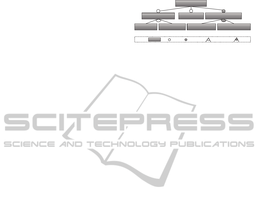
Figure 1: Subset of the eTe feature tree.
ilar software systems. All of them contain the same
functional core but may differ in quantity or pres-
ence of other functional components. All customers
can decide independently which components to se-
lect for their business. Such related software sys-
tems are called a software family. Obviously, this
scenario contains a dimension of variability which is
necessary to be controlled and managed. It has to be
avoided that, for a new customer, an existing product
is replicated and then customized because of the sin-
gle source principle. It is hardly possible to consis-
tently fix potential bugs in each and every customer
product which may differ only slightly. This un-
managed redundancy results in huge maintenance ef-
fort (Murer et al., 2010). As a consequence, the tech-
niques and methodologies of SPL engineering (Pohl
et al., 2005) are applied in software development.
Software product line engineering defines a fam-
ily of closely related software systems consisting of
common and variable functionality in order to man-
age variability. It aims at separating configuration
knowledge, regarding what functionalities belong to
a concrete product, from the actual realization of that
product. Thus, one main benefit of SPL engineeringis
that configuration knowledge is captured on a concep-
tual non-technical level, and hence can be accessed by
non-programmers easily. Therefore, problem space
and solution space are distinguished. The former con-
sists of the conceptual configuration knowledge and
the latter contains the artifacts realizing desired func-
tions (Czarnecki and Eisenecker, 2000).
The variability in the problem space is commonly
described with feature models (Kang et al., 1990)
wherein features are arranged in a feature tree (Chen
et al., 2005). Selecting one feature in the tree auto-
matically selects its parent feature. To determine if
a feature is mandatory or optional it can be marked
as such. Furthermore, features can be combined into
or groups or alternative groups. The former allows
selecting at least one child feature, whereas exactly
one feature must be selected (in terms of an
xor
se-
lection among the child features) from the latter. Be-
yond that, cross-tree constraints can be specified over
the features to express relations not being able to be
reflected in the tree structure (Batory, 2005).
In Figure 1, a small subset of the eTe feature
DATA2015-4thInternationalConferenceonDataManagementTechnologiesandApplications
126

Component
Developer
Configuration
Partner
Deployment
Partner
Development
Time
Generation
Time
Deployment
Time
Components
SPL
Feature Model
Products
Customer
Component
Evolution
Product
Evolution
Database
Evolution
Figure 2: SPL engineering process.
tree is illustrated. It contains the root feature
eTe
System
having the mandatory child feature
Master
Data Mgmt
. Its children (
Customer Data
and
Stock
Mgmt.Data
) reside in an or group, thus at least one of
them must be selected. The two features
Reporting
System
and
Stock Mgmt
are optional. If the for-
mer is selected, then either a
centralized
or a
decentralized
reporting system needs to be se-
lected, since both features are contained within an
alternative group. Furthermore, the cross-tree con-
straint ensures that if the
Stock Mgmt.Data
feature
is selected, the
Stock Mgmt
feature must be selected,
too. A feature tree represents all possible configura-
tions whereas a configuration is a valid subset of all
features satisfying all constraints and selection rules.
Thus, a feature model is a compact and concise nota-
tion of a large number of possible configurations.
Transforming a conceptual configuration into an
executable software system poses two prerequisites.
First, a mapping from problem space to solution space
must be specified to define the semantics of the par-
ticular features. Within the eTe project, we decided
to establish a 1:1 mapping of feature (problem space)
to software component (solution space) for the sake
of simplicity. Second, a variability realization mech-
anism is needed producing the final product w.r.t the
configuration. The final product is called a variant.
3 EVOLUTION OF SPLs
SPLs allow generating new products whenever the
customer’s requirements change or new versions of
chosen features are published. This flexibility hits the
wall at the database layer. Typically, customers want
to keep their data when updating their products. In-
evitably, evolution in SPLs includes the evolution of
databases, which is still a major headache in practice.
SPLs involve three major program life cycle phases:
development time, generation time, and deployment
time, as illustrated in Figure 2. All three phases are
decoupled regarding when they happen (time) and in
whose domain they are performed (space).
At development time, a component developer im-
plements a component that realizes a specific feature
in the SPL. Components are purely additive and do
not alter the other components, but they may extend
others. If a component requires persistence, the de-
veloper defines the corresponding data model for the
component. To make a component available, the de-
veloper submits the code and a formal component de-
scription (name and its dependencies to other compo-
nents) to a central component repository.
At generation time, aconfigurationpartner selects
a specific set of features required by a customer. A
configurator tool provides a convenient UI for this
task. Once a variant of the SPL is configured, the
configurator compiles the product desired by the in-
dividual customer by resolving the selected features
to software components w.r.t. the mapping between
problem and solution space. The database schema
for the product results from the union of the database
schemas of the selected components.
At deployment time, a deployment partner de-
ploys an individual product on its runtime platform
and makes it available to the customer. Since prod-
uct deployment is decoupled from component devel-
opment, many individual products can be deployed
easily for very different customers. During product
deployment, the database is set up and tables are cre-
ated according to the product’s database schema.
Evolution can occur in all three phases. At de-
velopment time, developers improve, update, refactor,
and debug their components including the underlying
data model. We call this component evolution. At
generation time, customers request reconfiguration of
their products, because they want to add/remove com-
ponents or update to a new component version, re-
sulting in product evolution. At deployment time, we
have to consistently evolve an existing database, in-
cluding schema and data, according to the new prod-
uct version. This is database evolution. Database
evolution is necessary if the data model of a product
changes in component or product evolution and these
changes are actually rolled out to the customer.
Consider the small example in Figure 3. It shows
the component evolution of the componentsC
1
andC
2
with their respective data models. The data model of
C
1
consists of a table
Article
with three columns.
C
2
builds on that data model and adds the column
weight
to
Article
. Say a customer runs a product
with configuration {C
1
} and wants to change to con-
figuration {C
1
, C
2
}. In case of this product evolution,
the database has to evolve, too. After adding the col-
DatabaseEvolutionforSoftwareProductLines
127
Article
(…, weight)
Article
(id, name, description)
Article
(…, value, measure)
ܥ
ଵ
ܥ
ଶ
ܥ
ଶ
Ԣ
General_Cargo
(…, value, measure)
General_Cargo
(id, name, description)
Bulk_Cargo
(id, name, description)
ܥ
ଵ
Ԣ ܥ
ଶ
ԢԢ
Component Evolution
Software Product Line
Component Evolution
Dependency
Legend:
{C
1
} → {C
1
, C
2
}
{C
1
} →
C
1
, C
′
2
{C
1
} →
C
′
1
{C
1
} →
C
′
1
, C
′′
2
{C
1
, C
2
} → {C
1
}
{C
1
, C
2
} →
C
′
1
{C
1
, C
2
} →
C
1
, C
′
2
{C
1
, C
2
} →
C
′
1
, C
′′
2
C
1
, C
′
2
→ {C
1
}
C
1
, C
′
2
→
C
′
1
C
1
, C
′
2
→
C
′
1
, C
′′
2
C
′
1
→
C
′
1
, C
′′
2
C
′
1
, C
′′
2
→
C
′
1
Figure 3: Example for evolution in SPLs.
umn
weight
, the evolution has to add
weight
values
for all existing articles, e.g., by inferring
weight
val-
ues from the product description.
Later on, a new version of C
2
, called C
′
2
, is re-
leased. Instead of
weight
, C
′
2
uses the two columns
value
and
measure
to represent the weight of an
article. This component evolution does not cause a
database evolution as long as no product is evolved to
includeC
′
2
. If a product evolves to includeC
′
2
, the new
columns
value
and
measure
of already existing arti-
cles must be populated, e.g., splitting existing
weight
values (e.g. 5 kg, 500g) into
value
and
measure
.
In another component evolution, C
1
is updated
to C
′
1
. For C
′
1
, the component developer decides to
change the data model. Because general cargo and
bulk cargo are often handled separately, the devel-
oper horizontally partitions the
Article
table into the
tables
General_Cargo
and
Bulk_Cargo
. C
′
2
is not
compatible with this new version C
′
1
. The developer
of C
′
2
reacts and updates the component to C
′′
2
. In C
′′
2
,
the additional columns only extend
General_Cargo
since bulk cargo does not have any fixed weight.
As shown in the example, the data transformation
for an evolution step, e.g., inferring new values or
splitting existing values, depends on the application
logic that uses the data. In the context of SPLs, only
the component developer knows the specifics of the
application logic and is able to specify the data trans-
formation necessary for the component’s evolution.
The example in Figure 3 already involves five pos-
sible configurations of a product and thirteen possible
product evolutions, in total. The large – in the ex-
treme case exponential – number of possible config-
urations and product evolutions in SPLs is intended
by design. The combinatorial explosion is the true
power of SPLs and allows providing highly individual
products to customers. Nevertheless, it is absolutely
infeasible for a component developer to consider all
product evolutions a component may be involved in.
In SPLs, database evolution can be specified only lo-
cally at development time with a scope limited to the
new component, its predecessor, and all components
the new component depends on.
At deployment time, when database evolution ac-
tually happens, the locally defined evolution scripts
form one global evolution script. The global evolu-
tion script carries out the database evolution for one
specific product evolution. The key challenge to im-
plement database evolution for SPLs is to weave all
relevant local evolution scripts to one global evolu-
tion script. We call this the weaving problem.
Consider an evolution from {C
1
, C
′
2
} to {C
′
1
, C
′′
2
}
from Figure 3. The local script for the evolution
C
1
→ C
′
1
creates the two new tables
General_Cargo
and
Bulk_Cargo
, moves the data from
Article
to the new tables, and drops
Article
. The local
script for the evolution C
′
2
→ C
′′
2
creates the columns
value
and
measure
in the
General_Cargo
table,
moves data from the
Article
table to the new tables,
and removes the columns
value
and
measure
from
Article
table. Obviously, these local evolutions have
dependencies, which prohibit sequential execution.
The weaving problem has two aspects. On the
logical level the global evolution script has to be cor-
rect. It must not result in a database different from
the component developers’ intent. For each compo-
nent of the new product the resulting database has
to provide the expected structures. On the physical
level the global evolution script has to be efficient. It
is efficient if it performs the necessary change to the
database in the shortest possible time with a minimum
amount of resources. DAVE solves the weaving prob-
lem on the logical level. The physical optimization
of a global evolution script could not be addressed
in the eTe project so far and is open for future work.
Hence, there is no evaluation containing e.g. perfor-
mance measures. We focus on the logical level and
validate the feasibility within our industry project.
4 DATABASE EVOLUTION
TOOLKIT DAVE
DAVE implements a demonstrator for the eTe SPL in-
cluding a solution for the logical level of the weaving
problem. In this section, we describe the developed
process and its tool support. Well in line with SPL
engineering, DAVE stores all required information for
data management in an abstract format locally within
each component. During the configuration and gen-
eration of a customized product, this information is
simply collected from all participating components.
Finally, DAVE generates one global database evolu-
tion script for each deployment, depending on the pre-
DATA2015-4thInternationalConferenceonDataManagementTechnologiesandApplications
128

DB
Development
Tool
Component
Database Folder
Configurator
DB
Deployment
Tool
Development Generation
Deployment
Previous version,
Dependencies
Configuration
SPL Repository
Customer Product
Database
Folders
Database
Folders
Database
Folders
Component
Customer Product
Database
Folders
Database
Folders
Database
Folders
Current Configuration
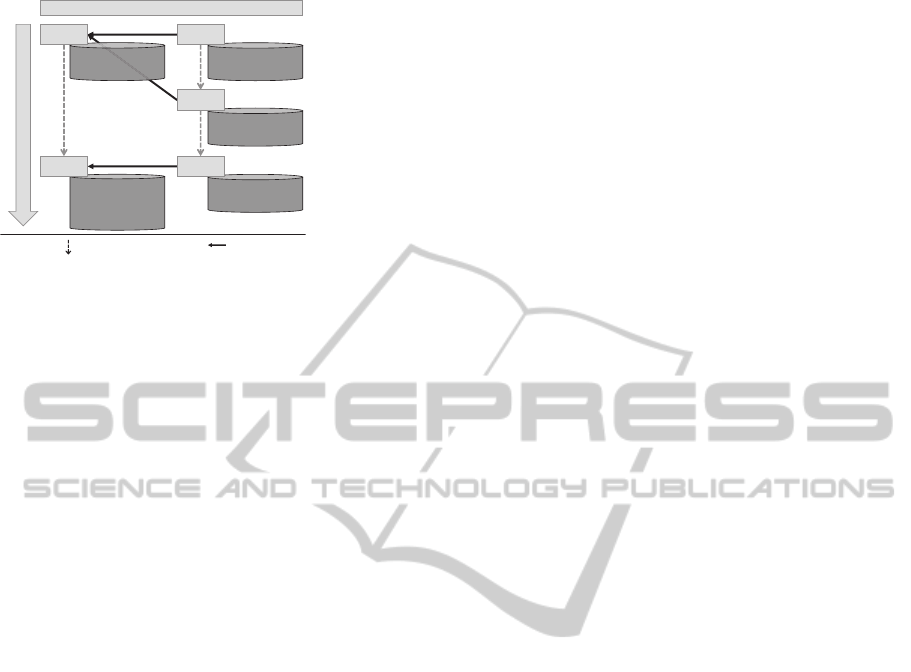
Figure 4: Data management process for SPL engineering.
vious and the new configuration.
The data management process of DAVE, as shown
in Figure 4, is based on the general process descrip-
tion for SPL engineering in Figure 2. The develop-
ers use the domain-specific language (DSL) HEDL to
describe the data model. When developing a com-
ponent, we create a database folder containing the
local database evolution steps, which are defined us-
ing Liquibase (http://www.liquibase.org). Liquibase
simplifies the handling of database evolution, is inde-
pendent of the concrete relational DBMS, and allows
determining the difference between given schemas.
The DB Development Tool creates the database folder
based on the new component and its previous version,
if existing. We discuss the DB Development Tool in
Section 4.1. Generation time requires no additional
database-related tool support. Basically, all database
folders of the selected components are collected and
included in the final customer product. At deployment
time, the DB Deployment Tool weaves the collected
information into one executable Liquibase script, as
described in Section 4.2. The DB Deployment Tool is
the heart of DAVE; this is where the weaving problem
is solved.
4.1 DB Development Tool
The single components of an SPL are developed sep-
arately. It is unforeseeable, which other components
will also be part of a deployed product. Nevertheless,
these other components may use or extend the com-
ponent’s data model. The DB Development Tool of
DAVE ensures, that all necessary information about a
component is collected locally at developmenttime to
deploy any product globally.
Input. Developers specify a component’s
data model using Hibernate Entity Definition Lan-
guage (DevBoost, 2013) (HEDL). HEDL is a DSL
being able to generate the Java Persistence API (JPA)
layer of an application, which is responsible for per-
sisting and accessing data in a relational database.
HEDL has a concise syntax for defining the persis-
tence layer of a specific domain. A HEDL document
is transformed to Java entity classes and data access
object classes automatically. HEDL can be used for
Hibernate or any other JPA implementation. For in-
stance, the component C
1
from the example in Fig-
ure 3 is described as shown in Listing 1.
1
Article {
2 String
identifier;
3 String
name;
4 String
description;
5
}
Listing 1: HEDL model for C
1
.
A major advantage of HEDL is the intuitive
and powerful mechanism for data model extensions
through composition. Thus, new persistence layers
can be generated by reusing and extending existing
domain models. Listing 2 shows the HEDL file of the
component C
′
2
, which adds further attributes to C
1
.
1 extendModel
="c1.hedl"
2
Article {
3 Int
value;
4 String
measure;
5
}
Listing 2: HEDL model for C
2
.
The developer of C
′
2
directly works with a gener-
ated Java class for the
Article
, including the defined
attributes. A Hibernate mapping is generated, which
allows creating and accessing the database schema.
DAVE’s DB DevelopmentTool takes the new schema,
the previous version of the component, and all depen-
dencies of the new version as input.
Output. The output is a representation of the
delta between the previous and the current version
of the component. The DB Development Tool adds
the database folder to the component’s source, con-
sisting of three files and two subfolders. First, the
file
dependencies.xml
collects the components and
their versions, which are used or extended by the com-
ponent project. Second, the
ini.liqui.xml
file is
the Liquibase script which creates the component’s
schema from scratch or by extending existing depen-
dencies. Third, the
evolve.liqui.xml
file contains
Liquibase operations to transform the previous ver-
sion of the component into the new one. Fourth, the
history
folder contains the database folders from
all previous versions of the component. This is nec-
essary to perform updates even on older versions
than the previous one. Fifth and finally, the
sql
folder contains SQL scripts, which are linked from
DatabaseEvolutionforSoftwareProductLines
129

ini.liqui.xml
and
evolve.liqui.xml
, describing
the evolution of the data. To realize the evolution
of existing data during deployment, the DB Devel-
opment Tool generates SQL templates into the
sql
folder for each new column or table. The developer
has to fill these templates manually. Nevertheless, the
generated templates guide the developer through this
task. Given the evolution to C
′
2
, DAVE generates an
update statement template for the new columns
value
and
measure
of the
Article
table. The developer can
assume the old table
Article
to be still present.
Implementation. The algorithm to create the
initialization file and the evolution file uses two
databases (DB
new
and DB
ref
) and Liquibase’s fea-
ture to compare given database schemas. To cre-
ate the
ini.liqui.xml
file, three steps are neces-
sary: First, we use the generated Hibernate map-
ping to create the component’s database schema to
DB
new
. The extension mechanism of HEDL inher-
ently initializes all dependencies. Second, we create
the schema of a customer product, containing exclu-
sively the component’s dependencies, using their ini-
tialization scripts, to DB
ref
. Finally, we use Liquibase
to compare the two database schemas and retrieve the
ini.liqui.xml
file. To enrich this schema evolution
with data evolution, we create SQL templates for ev-
ery new column or table, store them in the
sql
folder,
and link them from the Liquibase script. The tool gen-
erates an
UPDATE
statement for each table including
new columns and an
INSERT
statement for each new
table. The component developer has to use these tem-
plates to specify the new values depending on the old
data, provided by the existing dependencies. For in-
stance, the initialization script of component C
′
2
adds
two columns to the table
Article
and generates tem-
plates for the corresponding update statements. Af-
ter completing the SQL templates, the initialization
script is finished and ready to use for any initial de-
ployment of the component.
If there is a previous version of the component,
the evolution is stored in the
evolve.liqui.xml
file.
The DB Development Tool creates it by executing the
following four steps: First, we create the schema of
the new componentto DB
new
using its Hibernate map-
ping. Second, we initialize the previous version using
the initialization script of the predecessor and the pre-
decessor’s dependencies to DB
ref
. Third, we adjust
the dependencies to match the new component ver-
sion. This includes three possible scenarios: adding
a dependency (
ini.liqui.xml
), removing a depen-
dency (inverse of
ini.liqui.xml
), and updating a
dependency (
evolve.liqui.xml
). Finally, we again
use Liquibase to diff between DB
new
and DB
ref
to ob-
tain the evolution script
evolve.liqui.xml
and gen-
erate the SQL templates for data evolution. When fill-
ing the generated SQL templates, the developer may
assume the previous version to be still present.
Consider the evolution from C
′
2
to C
′′
2
, in the gen-
erated evolution script, we add the two attributes to
General_Cargo
. We do not need to remove the pre-
vious columns added to
Article
, since this whole re-
lation is dropped by the evolution of C
1
to C
′
1
. How-
ever, in the SQL statement templates we assumed the
Article
table to be still present and transform the
data to the new version. This database evolution script
is sufficient to execute any deployment including the
database evolution between arbitrary configurations.
Please note, that DAVE does not support evolution to
predecessor versions of components.
4.2 DB Deployment Tool
After the development and the generation, a concrete
customer product is ready to being deployed. If the
customer already runs an older version of his prod-
uct, the deployment has to keep the old data and
transform it according to the new configuration. The
concrete evolution script will be derived by DAVE’s
DB Deployment Tool from the generic description in
the database folder of each component. As a conse-
quence, the deployment of products and the develop-
ment of single components are decoupled completely.
Input. The SPL contains components, including
their created database folders. After the customer
chooses the desired features from the feature model,
the corresponding componentsare composed to the fi-
nal product. The local database folders of these com-
ponents are simply collected and serve as input for
the deployment step. Another important input is the
previous product and its configuration (the set of pre-
viously installed components and their version num-
bers). This is necessary to determine for each compo-
nent whether it is evolved, added, removed, or stays
unchanged.
Output. The DB Deployment Tool creates a
global Liquibase script for the database evolution. It
ensures the correct evolution of both schema and data
of the currently installed product to the new one.
Implementation. To generate a correct database
evolution script for a customer’s deployment, the DB
Deployment Tool considers the currently installed
configuration and derives the necessary steps to ob-
tain the new one. Figure 3 shows possible configu-
rations according to the example in Figure 3. As an
example, let us consider the product evolution from
{C
1
, C
′
2
} to {C
′
1
, C
′′
2
}. Given the new and the previous
configuration, DAVE determines the sets of added, re-
moved, and updated components and collects the re-
DATA2015-4thInternationalConferenceonDataManagementTechnologiesandApplications
130

quired Liquibase operations respectively. These oper-
ations originate either from the initialization script, its
inverse, or the evolution script. In case a component’s
update skips versions, the tool also includes the corre-
sponding evolution scripts from the
history
folder.
DAVE’s DB Deployment Tool interleaves the col-
lected database operations, since it is not feasible
to simply execute the whole scripts sequentially.
Evolution steps may influence each other. For in-
stance, the evolution of C
1
to C
′
1
creates the tables
General_Cargo
and
Bulk_Cargo
, inserts the data
from the table
Article
accordingly, and finally drops
Article
. The evolution of the additional component
from C
′
2
to the version C
′′
2
adds the two columns to
General_Cargo
and inserts the data from
Article
.
It can be applied neither before nor after the evolution
of the component C
1
. If the evolution to C
′′
2
is ex-
ecuted first, the table
General_Cargo
is not created
yet and the addition of the new columns and the in-
sertion of data would fail. If the evolution to C
′′
2
is
executed last, the original
Article
table is already
dropped including the data in the additional columns.
This is, in its essence, the weaving problem.
The DB Deployment Tool solves the weaving
problem with the help of operation groups. It
groups database operationsof the same kind across all
components and arranges these groups sequentially.
Mainly, there are seven phases in the resulting evolu-
tion script. First, the DB Deployment Tool executes
all database operations that add information capacity
to the schema, like (1) creating tables or (2) adding
columns. Afterwards, (3) all obsolete constraints are
removed to (4) execute data evolution. At this point,
DML and DQL operations can access new schema el-
ements and also the old ones. The previously existing
data is still fully available and can be inserted into the
also existing new structures. Finally, the DB Deploy-
ment Tool executes all database operations that reduce
the information capacity, like (5) removing columns
or (6) dropping tables, to obtain the desired schema.
This also includes (7) adding new constraints.
Within an operation group, the DB Deployment
Tool orders all operations according to the topological
order of the original components regarding their de-
pendencies. Multiple operations of one component in
one group remain in the order specified by the devel-
oper. In our example, the previously installed product
uses the
Article
table with the additional
value
and
measure
attributes. The final evolution script would
start by (1) creating the new tables
General_Cargo
and
Bulk_Cargo
, (2) adding the
value
and
measure
attribute, and (4) inserting the data of C
1
into C
′
1
and updating the additional attributes of C
′′
2
using the
original
Article
table. Afterwards, it (6) drops the
Article
table and (7) adds the not-null constraints to
the newtables. This finally creates the desired schema
including the transformed data.
5 RELATED WORK
While software product lines are an exhaustively stud-
ied subject in software engineering, database man-
agement issues in SPLs are underrepresented in re-
search. According to the perception that a database
consists of its schema and its data, we distinguish
database schema evolution and accordant data evolu-
tion in SPLs. Both aspects of database evolution in
SPLs are relevant for the consistent evolution of com-
ponents and products as motivated in Section 3.
Variable database schemas in SPLs are studied
in (Khedri and Khosravi, 2013) and (Abo Zaid and
De Troyer, 2011). Modeling data variability in SPLs
is typically based on feature modeling as used in SPL
engineering. In (Abo Zaid and De Troyer, 2011), a
variable data model is introduced. Before variability
of data concepts in the variable data model can be de-
fined, persistency features in the feature model of the
SPL are specified by the extended Feature Assembly
Modeling Technique (Abo Zaid et al., 2010). How-
ever, this technique only considers the initial deriva-
tion of a product’s database schema.
The evolution of a database schema for an SPL
product is analyzed in (Khedri and Khosravi, 2013).
Delta-Oriented Programming is used to add delta
modules, defined by SQL DDL statements, to a core
module incrementally, based on the product config-
uration. Database constraints are generated for the
delta scripts to ensure a valid global database schema.
To the best of our knowledge, there is no research
on data evolution in software product lines. In our un-
derstanding of SPL evolution (cf. Figure 3), compo-
nent evolution is closely related to database refactor-
ing (Ambler and Sadalage, 2006). There is sufficient
support for database evolution of one running prod-
uct, like e.g. Liquibase or Rake. However, the SPL
evolution, hence the weaving problem, still requires
in-depth research. It requires the generation of global
evolution scripts from the component’s local scripts.
Since the management of a software product line and
the derivation of its products is mostly model-based,
results from model-driven engineering research are
relevant. In (Milovanovic and Milicev, 2013) it is re-
ported about a pragmatic and efficient solution to the
problem of schema evolution affecting existing pro-
grams, in the domain of model-driven development
of database applications using Unified Modeling Lan-
guage (The Object Management Group, 2010) (UML)
DatabaseEvolutionforSoftwareProductLines
131

models. The main contribution of this paper is a semi-
automatic algorithm for differencing structural UML
models and upgrading the relational schema, as well
as a tool that has been evaluated in a large-scale e-
government human resources management system.
6 CONCLUSIONS
In the eTe project, we laid our focus on an impor-
tant but widely unstudied problem: database evolu-
tion in SPLs. SPLs decouple the development of the
components from the actual deployment of products.
The developer of a component specifies its local data
model. According to a customer’s requirements, such
components are composed to a product. The global
database schema of such a product is derived by com-
posing the local schemas of all components.
Since evolution is inevitable, the customer’s prod-
uct will evolve, including the addition, removal, or
update of components. The customer relies on a con-
sistent database, which has to be evolved accordingly.
Consequently, the database evolution during deploy-
ment requires to derive the specific global evolution
script from given local definitions within the compo-
nents. Creating a correct (logical) and efficient (phys-
ical) evolution script is called the weaving problem.
Obviously, this is a general problem, which is not
restricted to the eTe scenario. To achieve a valuable
general solution, we first discussed the general prob-
lem of (database) evolution in SPLs and formulated
general challenges. We presented DAVE, a database
evolution toolkit for the eTe SPL. It weaves the local
evolution scripts to a global evolution script by group-
ing the single database operations into groups, which
are then executed sequentially. Within each group,
the operations follow the topological order according
to defined dependenciesbetween components. Within
each component, the original order is kept.
DAVE solves the weaving problem on the logical
level. We successfully tested DAVE on realistic evo-
lution scenarios based on the detailed experience of
the industry partners. It emerged as being capable of
realizing database evolution for eTe. DAVE retains
a lean runtime architecture, since DAVE does not in-
troduce any additional layer at runtime for database
evolution. Developers can rely on commonly known
tools and technologies, which was an important re-
quirement of the eTe project.
The concepts of DAVE are universal and applica-
ble to SPLs in general. SPLs and their evolution are
promising trends in software and database technology
and we consider DAVE as an important contribution
particularly because of its practical background.
ACKNOWLEDGEMENTS
We thank our partners of the eTe project. This re-
search has been co-funded by the European Regional
Development Fund in the project #100135681/2804.
REFERENCES
Abo Zaid, L. and De Troyer, O. (2011). Towards Modeling
Data Variability in Software Product Lines. In En-
terprise, Business-Process and Information Systems
Modeling, volume 81 of Lecture Notes in Business In-
formation Processing. Springer Berlin Heidelberg.
Abo Zaid, L., F., K., and De Troyer, O. (2010). Feature As-
sembly Modelling: A New Technique for Modelling
Variable Software. In 5th International Conference
on Software and Data Technologies Proceedings, vol-
ume 1, pages 29 – 35. SciTePress.
Ambler, S. W. and Sadalage, P. J. (2006). Refactoring
Databases: Evolutionary Database Design. Addison-
Wesley Professional.
Batory, D. (2005). Feature Models, Grammars, and Propo-
sitional Formulas. In Obbink, H. and Pohl, K., ed-
itors, Software Product Lines, volume 3714 of Lec-
ture Notes in Computer Science, pages 7–20. Springer
Berlin Heidelberg.
Chen, K., Zhang, W., Zhao, H., and Mei, H. (2005). An
approach to constructing feature models based on re-
quirements clustering. In Requirements Engineering,
2005. Proceedings. 13th IEEE International Confer-
ence on, pages 31–40.
Czarnecki, K. and Eisenecker, U. W. (2000). Genera-
tive Programming: Methods, Tools, and Applica-
tions. ACM Press/Addison-Wesley Publishing Co.,
New York, NY, USA.
DevBoost (2013). HEDL - Hibernate Entity Definition Lan-
guage (Hibernate DSL - User Guide).
Kang, K. C., Cohen, S. G., Hess, J. A., Novak, W. E., and
Peterson, A. S. (1990). Feature-oriented domain anal-
ysis (FODA) feasibility study. Technical report, DTIC
Document.
Khedri, N. and Khosravi, R. (2013). Handling Database
Schema Variability in Software Product Lines. In Soft-
ware Engineering Conference (20th APSEC.
Lehman, M. M. (1980). Programs, life cycles, and laws of
software evolution. Proceedings of the IEEE.
Milovanovic, V. and Milicev, D. (2013). An interactive tool
for UML class model evolution in database applica-
tions. Software & Systems Modeling, pages 1–23.
Murer, S., Bonati, B., and Furrer, F. J. (2010). Managed
Evolution: A Strategy for Very Large Information Sys-
tems. Springer Berlin/Heidelberg.
Pohl, K., Böckle, G., and Van Der Linden, F. (2005). Soft-
ware Product Line Engineering - Foundations, Prin-
ciples and Techniques. Springer Berlin/Heidelberg.
Roddick, J. F. (1995). A survey of schema versioning is-
sues for database systems. Information & Software
Technology, 37(7):383–393.
DATA2015-4thInternationalConferenceonDataManagementTechnologiesandApplications
132

Terwilliger, J. F., Cleve, A., and Curino, C. A. (2012). How
clean is your sandbox? In ICMT, volume 7307.
The Object Management Group (2010). OMG Unified
Modeling Language TM (OMG UML), Superstruc-
ture, Version 2.3.
DatabaseEvolutionforSoftwareProductLines
133
