
VNetIntSim
An Integrated Simulation Platform to Model Transportation and Communication
Networks
Ahmed Elbery
1
, Hesham Rakha
1
, Mustafa Y. ElNainay
2
and Mohammad A. Hoque
3
1
Dept. of Computer Science, Dept. of Civil Engineering, Virginia Tech, Blacksburg, VA, U.S.A.
2
Dept. of Computer and Systems Eng, Alexandria University, Alexandria, Egypt
3
Dept. of Computing, East Tennessee State University, Johnson City, U.S.A.
Keywords: VANET, ITS, Modelling, Simulation.
Abstract: The paper introduces a Vehicular Network Integrated Simulator (VNetIntSim) that integrates transportation
modelling with Vehicular Ad Hoc Network (VANET) modelling. Specifically, VNetIntSim integrates the
OPNET software, a communication network simulator, and the INTEGRATION software, a microscopic
traffic simulation software. The INTEGRATION software simulates the movement of travellers and
vehicles, while the OPNET software models the data exchange through the communication system.
Information is exchanged between the two simulators as needed. As a proof of concept, the VNetIntSim is
used to quantify the impact of mobility parameters (traffic stream speed and density) on the communication
system performance, and more specifically on the data routing (packet drops and route discovery time).
1 INTRODUCTION
Vehicular Ad Hoc Networks (VANETs) and
Intelligent Transportation Systems (ITSs) have a wide
spectrum of applications, algorithms and protocols
that are important for the public, commercial,
environmental and scientific communities. From the
communication perspective, these applications range
from on-road-content-sharing Li, Yang et al. (2011),
entertainment-based and location-based services
(Bruner 2007). From the transportation perspective,
these applications include safety applications (Hafeez,
Lian et al. 2010), cooperative driving and warning
applications (Van den Broek, Ploeg et al. 2011),
traffic control and management (Baskar, De Schutter
et al. 2007), fuel consumption and carbon emission
minimization applications (Xiao, Zhao et al. 2012),
speed harmonization (Talebpour, Mahmassani et al.
2013), road traffic congestion detection and
management (Roy, Sen et al. 2011), and taxi/transit
services (Mohammad A. Hoque 2014). This wide
application spectrum demonstrates the importance of
these systems.
On the other hand, evaluating these systems is
challenging, not only because of the cost needed to
implement these systems because of the need for a
large number of vehicles equipped with
communication devices, the required communication
infrastructure and signal controllers, but also for the
need for roads to run the required experiments. A third
reason is that some applications/algorithms work in
special conditions of either weather and/or traffic
congestion, which are not easily provided. Fourthly,
and most importantly, the failures in some of these
applications may result in loss of lives of the
participants.
Thus, currently, the best solution for studying
these systems is to use simulation tools. However,
simulating ITS and VANET systems is challenging.
The reason is that these systems cover two fields,
namely the transportation field and the
communication field. The transportation field includes
the modeling of vehicle mobility applications
including traffic routing, car-following, lane-
changing, vehicle dynamics, driver behavior
modeling, and traffic signal control modeling, in both
macroscopic and microscopic modeling scales. The
other main field is the data and communication
network modeling that includes data packet flow,
vehicle-to-vehicle (V2V) communication as well as
vehicle-to-infrastructure (V2I) communication,
wireless media access, data transportation, data
security and other components. These two fields are
133
Elbery A., Rakha H., Y. ElNainay M. and A. Hoque M..
VNetIntSim - An Integrated Simulation Platform to Model Transportation and Communication Networks.
DOI: 10.5220/0005409401330143
In Proceedings of the 1st International Conference on Vehicle Technology and Intelligent Transport Systems (VEHITS-2015), pages 133-143
ISBN: 978-989-758-109-0
Copyright
c
2015 SCITEPRESS (Science and Technology Publications, Lda.)

not distinct or isolated, but instead are interdependent
and influence one another. For example vehicle
mobility, speeds and density affect the communication
links between vehicles (Hafeez, Lian et al. 2010) as
well as the data routes, and hence the communication
quality (i.e. reliability, throughput and delay) (Alam,
Sher et al. 2008). Another example is the attempt in
(Hoque, Hong et al. 2014) to model the multi-hop
V2V connectivity in urban vehicular networks using
archived Global Positioning System (GPS) traces that
revealed many interesting characteristics of network
partitioning, end-to-end delay and reachability of
time-critical V2V messages. In the opposite direction,
the number of packet losses between vehicles and the
delivery delay will affect the accuracy of the data
collected, and hence the correctness of the decisions
made by the ITS’s systems. Taking in consideration
the complexity of each system (transportation and
communication) in addition to the high and complex
interdependency level between them, we can see how
challenging the modeling and simulation of VANET
and ITS.
Most of the previous efforts in simulating VANET
and ITS platform are based on using fixed mobility
trajectories that are fed to the communication network
simulator. These trajectories may be generated off-
line using a traffic simulator platform or extracted
from empirical data sets. This simulation paradigm is
useful for single directional influence (i.e. studying the
effect of mobility on the network and data
communication) such as data dissemination in a
VANET. However, this approach cannot be used in
case the opposite direction of interdependence is
important (i.e. the effect of the communication system
on the transportation system). Such as vehicle speed
control in the vicinity of traffic signals, where vehicles
and the signal controllers exchange information to
compute and optimal vehicle trajectory. These
interactions have to be run in real-time to accurately
model the various component interactions.
In this paper, we introduce a new framework for
modeling and simulating an integrated VANET and
ITS platform. This new framework has the capability
of simulating the full VANET/ITS system with full
interdependence between the communication and
transportation systems, and hence allows for the
analysis of VANET and/or ITS applications and
algorithms with any level of interaction or
interdependence between them. This framework
integrates two simulators, namely; the
INTEGRATION (Rakha Accessed Aug. 2014) as
microscopic traffic simulator and the OPNET modeler
(Technology Accessed Aug. 2014) as the data and
communication simulator by establishing a two-way
communication channel between the models. Through
this communication channel, the two simulators can
interact to fully model any VANET/ITS application.
Subsequently, the developed framework is used to
study the effect of different traffic characteristics
(traffic stream speed and density) on V2V and V2I
communication performance.
The paper is organized as follows. Section II
provides a brief description of related work.
Subsequently, the VNetIntSim operation and how the
two simulators interact is described in section III. The
architecture of the VNetIntSim and the
implementation of the proposed framework is
presented in section IV. A simulation case study is
presented and discussed in section V, in which the
VNetIntSim is used to study the effect of various
traffic mobility measures on the communication
performance. Finally, conclusions of the study and
future research directions are presented in Section VI.
2 LITERATURE REVIEW
The necessity of integrating a full-fledged traffic
simulator with a wireless network simulator to model
the cooperative ITS systems built on V2X
communication platform has been perceived since the
past decade. A number of attempts have been made
within recent years to develop an integrated traffic
simulation platform that allows the vehicles’ mobility
conditions dynamically adapt to the wirelessly
received messages. Two different approaches have
been considered by the researchers to facilitate this
inter-operability.
One common approach was to embed the well-
known vehicular mobility models into the established
network simulators. These features are sometimes
combined with the original simulator as separate
functional modules or APIs. For example, Choffnes et.
al. (Choffnes and Bustamante 2005) integrated the
Street Random Waypoint (STRAW) model into the
Java-built scalable communication network simulator
SWANS, which allowed parsing of real street map
data and modeling of complex intersection
management strategies. A collection of application-
aware SWANS modules, named as ASH, were
developed to incorporate the car-following and lane-
changing models providing a platform for evaluating
inter-vehicle Geo-cast protocols for ITS applications
(Choffnes and Bustamante 2005, Ibrahim and Weigle
2008). Following a similar approach, the
communication network simulator NCTUns extended
its features to include road network construction and
microscopic mobility models (Wang and Chou 2009).
VEHITS2015-InternationalConferenceonVehicleTechnologyandIntelligentTransportSystems
134

More recently, NS-3 has been engineered to
incorporate real-time interaction between a wireless
communications module and vehicular mobility
models using a fast feedback loop.
Another different approach is to integrate two
standalone simulators - a traffic simulator coupled
with a wireless network simulator. The choice of
traffic simulators considered by the community for
coupling in this manner included CORSIM, VISSIM,
SUMO whereas network simulators ranged from NS-
2, NS-3, QUALNET, and OMNET++. Table 1
summarizes some of these integration attempts:
Table 1: Integrated Simulators Summary.
Traffic
Sim.
Network
Sim.
Integrated Simulator
VISSIM NS-2 MSIE (M. Caliskan)
SUMO NS-2
TraNS (Piorkowski,
Raya et al. 2008)
SUMO OMNET++
VEINS (Sommer,
German et al. 2011)
SUMO NS-3
OVNIS (Pigne, x et
al. 2010)
SUMO NS-3
iTETRIS
(Rondinone, Maneros
et al. 2013)
CORSIM is a commercial traffic simulator that
does not provide dynamic routing capabilities, while
VISSIM does provide some dynamic routing
capabilities these are limited compared to the
INTEGRATION software, which provides a total of
ten different routing strategies ranging from feedback
to predictive dynamic routing. Consequently, both
CORSIM and VISSIM do not provide sufficient
routing algorithms for testing in a connected vehicle
environment. The first attempt of integrating two
independent open source traffic and wireless
simulators was TraNS (Traffic and Network
Simulation Environment) (Piorkowski, Raya et al.
2008), which combined SUMO and NS-2. Later,
VEINS (Sommer, German et al. 2011) also adopted
the open source approach of TraNS by combining the
network simulator OMNET++ with SUMO. VEINS
allowed for the interaction between the two simulators
by implementing an interface module inside
OMNET++ that sends traffic mobility updating
commands to SUMO. For example, VEINS could
impose a given driving behavior to a particular vehicle
upon receiving wireless messages from another
vehicle. Most recently, the Online Vehicular Network
Integrated Simulation (OVNIS) (Pigne, x et al. 2010)
platform was developed, that coupled SUMO and NS-
3 together and included an NS-3 module for
incorporating user-defined cooperative ITS
applications. OVNIS extends NS-3 as a ‘‘traffic aware
network manager’’ to control the relative interactions
between the connected blocks during the simulation
process. Last but not the least, iTETRIS (Rondinone,
Maneros et al. 2013) moves one step beyond the state-
of-the-art solutions and overcomes one limitation that
is present in Trans, VEINS and OVNIS by providing
a generic central control system named iCS to connect
an open-source traffic simulator with a network
simulator, without having to modify the internal
modules of the interconnected simulation platforms.
VNetIntSim uses the concept of separation
between the internal simulators modules and the new
modules that were added to support the model
integration. This feature is actually inherited from the
two simulators we selected for the VNetIntSim.
INTEGRATION is fully built in modular fashion with
a master module that manages and controls of all the
modules. The interaction between the modules is
modeled using interfaces between the modules.
Consequently, updating any modules will not affect
the others as long as this interface does not change.
OPNET is built in a hierarchical modular fashion at all
its levels (network, nodes, links and processes). The
network consists of a set of nodes and links. Each node
consists of a set of process modules. The process
modules interact through interrupts and the associated
Interface Control Information (ICI). The modules
added to the simulators in this research effort maintain
the same concept, so that updating the simulators does
not affect the integration between them.
OPNET and INTEGRATION have their unique
features compared to the other simulators. Compared
to NS-2 and NS-3, OPNET has these features; 1) a
well-engineered user interface that allows for easy
building and managing of different simulation
scenarios. 2) the OPNET modeler provides its
powerful debugging capabilities. 3) OPNET supports
a visualization tool that allows for tracking data
packets within the nodes. OMNET++ is a simulation
framework that does not have modules. However,
there are many open source frameworks based on
OMNET++ that implement different modules such as
VEINS. In VEINS, the update interval is 1 second
which is a long interval from the communication
perspective. For example if the speed is the vehicle is
60 km/h (37.28 mi/h) which is a common speed in
cities, this update interval corresponds to 16.6 m
which is a long step that can affect the communication
between vehicles
From the traffic perspective, INTGRATION
supports many features, such as dynamic vehicle
routing and dynamic eco-routing, eco-drive systems,
VNetIntSim-AnIntegratedSimulationPlatformtoModelTransportationandCommunicationNetworks
135

eco-cruise control systems, vehicle dynamics and
other features that are not supported in other traffic
simulation software, including SUMO. The
INTEGRATION model has been developed over
three decades and has been extensively tested and
validated against empirical data and traffic flow
theory. Furthermore, the INTEGRATION software is
the only software that models vehicle dynamics,
estimates mobility, energy, environmental and safety
measures of effectiveness. The model also includes
various connected vehicle applications including
cooperative adaptive cruise control systems, dynamic
vehicle routing, speed harmonization, and eco-
cooperative cruise control systems.
3 VNetIntSim OPERATION
This section introduces the operation of the
VNetIntSim platform which integrates two
simulators; namely OPNET and INTEGRATION.
First, a brief introduction about INTEGRATION and
OPNET is presented. Then, the VNetIntSim operation
is described.
3.1 INTEGRATION Software
The INTEGRATION software is agent-based
microscopic traffic assignment and simulation
software (Rakha Accessed Aug. 2014).
INTEGRATION is capable of simulating large scale
networks up to 10000 road links and 500,000 vehicle
departures with time granularity of 0.1 second. This
granularity allows detailed analyses of acceleration,
deceleration, lane-changing movements, car
following behavior, and shock wave propagations. It
also permits considerable flexibility in representing
spatial and temporal variations in traffic conditions.
These are very important characteristics needed when
studying the communication between these vehicles.
The model computes a number of measures of
performance including vehicle delay, stops, fuel
consumption, hydrocarbon, carbon monoxide, carbon
dioxide, and nitrous oxides emissions, and the crash
risk for 14 crash types (Rakha Accessed Aug. 2014).
3.2 OPNET Modeler
The OPNET modeler is a powerful simulation tool for
specification, simulation and analysis of data and
communication networks (Technology Accessed Aug.
2014). OPNET combines the finite state machines
and analytical model. The modeling in OPNET uses
Hierarchical Modeling, which has a set of editors
(Network, Node and Process editors), all of which
support model level reuse. The most important
OPNET characteristic is that has been tested using
implementations for many standard protocols.
However, it does not yet support any VANET
technology protocols (i.e. IEEE 802.11p DSRC
(Jiang, Taliwal et al. 2006), nor Vehicular Routing
Protocols). Consequently, for now, the IEEE 802.11g
for wireless LAN simulation is used in the scenarios
and AODV (Perkins, Belding-Royer et al. 2003) for
routing purposes.
3.3 Integrating OPNET &
INTEGRATION
The main idea behind VNetIntSim is to use the
advantages of both the INTEGRATION and OPNET
platforms by establishing a two-way communication
channel between them. Through this channel the
required information is exchanged between the two
simulators. The basic and necessary information that
should be exchanged periodically is the vehicle
locations. The locations of vehicles are calculated in
INTEGRATION every deci-second and transmitted to
the OPNET modeler, which updates the vehicle
locations while they are communicating.
For this version of VNetIntSim, the
communication channel between OPNET and
INTEGRATION is established by using shared
memory as we will explain in the next section. The
shared memory supports the required speed and
communication reliability between the two simulators.
3.3.1 Initialization and Synchronization
When starting the simulators, and before starting the
simulation process, the two simulators should
initialize the communication channel using two-way
Hello Messages. After establishing the connection, the
two simulators synchronize the simulation
parameters; simulation duration, network map size,
location update interval, maximum number of
concurrent running vehicles and number of signals. In
this synchronization phase the INTEGRATION
serves as a master and OPNET serves as a slave, i.e.
values of these parameters in OPNET should match
those calculated in INTEGRATION. Mismatching in
some of these parameters (such as simulation duration,
number of fixed signal controllers and the maximum
number of concurrent running vehicles) will result in
stopping the simulators. In this case the OPNET
software sends a Synchronization Error message to the
INTEGRATION software. This behavior guarantees
the consistency of the operation and the results
VEHITS2015-InternationalConferenceonVehicleTechnologyandIntelligentTransportSystems
136
collected in both system. Additional parameters allow
some tolerances. For example, the map size in OPNET
should be greater than or equal to that in
INTEGRATION. If the map size does not satisfy this
condition, OPNET will send a Synchronization Error
message to INTEGRATION, and the simulation will
stop.
After successful synchronization, the simulation
process should start by exchanging the simulation start
message sent from OPNET.
During the simulation phases, there are many types
of messages that can be exchanged between the two
simulators. Each message type has its unique Code.
Based on the code, the message fields are determined.
Table 2 shows the different message codes. The gaps
between the code values allow for the addition of new
functionalities in the future.
Table 2: Message Codes.
Code Function
01 Initialization; Hello Message
02 Initialization refused
10 Parameter Synchronization
11 Synchronization Error
30 Signal Locations Request
31 Signal Locations Updates
40 Start Simulation
50 Locations Information Request
51 Locations Information Updates
60 Speed Information Request
61 Speed Information Updates
99 Termination Notification
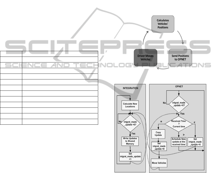
3.3.2 Location Updating
During the simulation, the INTEGRATION software
computes the new vehicle coordinates and sends them
to the OPNET software, which in turn updates the
location of each vehicle, as shown in Figure 1. This
cycle is repeated each update_interval, which is
typically 0.1 seconds in duration. The time
synchronization during the location updating is
achieved in two ways, 1) using two semaphores
(intgrat_made_update and opnet_made_update) one
for each simulator, 2) at each update time step the
INTEGRATION software sends the current
simulation time to OPNET. If it does not match the
OPNET time, OPNET will take the proper action to
resolve this inconsistency. Figure 2 shows the flow
chart for the basic location update process. In each
location update cycle, the INTEGRATION software
computes the updated vehicle locations.
Subsequently, it checks whether the last update has
been copied (intgrat_made_update = 0). If so, it writes
the new update to the shared memory and sets the
intgrat_made_update flag to 1.
OPNET waits for new updates. When it receives a
new update, if the received time equals its current
time, the driver process in OPNET will copy the
locations, set the intgrat_made_update flag to 0, and
then moves the vehicles to the new locations. If the
received time is greater than the OPNET current time,
it schedules the process to be executed again in the
received time. If the received time is less than the
current time, OPNET discards this update.
Figure 1: Location update cycle.
Figure 2: VNetIntSim basic operation.
3.3.3 Application Communication
The basic operation described above is only for
updating locations, which is the core of the
VNetIntSim platform. However, ITS applications
need the exchange of other types of information that
reflect the communication results to INTEGRATION.
This information and how/when it should be
exchanged depend mainly on the application itself.
Thus, the application specifications should define
VNetIntSim-AnIntegratedSimulationPlatformtoModelTransportationandCommunicationNetworks
137
what other information as well as how and when it
should be exchanged.
The applications will use the established
communication channel to exchange the required
information. VNetIntSim supports simultaneous
multi-applications, where each application can use
one or more codes to support its functionalities.
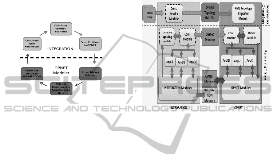
Figure 3 shows the complete communication cycle
when running an application.
Figure 3: Complete communication cycle.
For example, in variable speed control systems,
the integration will move the vehicles. Then, in
OPNET, the vehicles and signals communicate the
speed information. Based on the exchanged
information, each vehicle finds its new speed. These
new speeds should be sent to the INTEGRATION
software, which computes the updated parameters (i.e.
acceleration or deceleration) and then computes the
updated vehicle locations.
4 ARCHITECTURE AND
IMPLEMENTATION OF
VNETINTSIM
Figure 4 shows the VNetIntSim architecture and the
modules that were added to each simulator (dashed
boxes). Within INTEGRATION, the Configuration
Reader Module reads the input files and based on the
configuration generates an XML topology file for
OPNET. This topology file contains the vehicle
specifications, signal controller locations as well as
the application and profile specifications. This file is
used by OPNET to generate its scenarios.
The first issue that arises during implementation
entails identifying the inter-process communication
mechanism that should be used to connect the
simulators. In VNetIntSim two methods were
selected, namely; TCP sockets and shared memory.
Each of these methods has its advantages over all the
other methods. The shared memory approach supports
very high speed communication, which is needed
when modeling large simulation networks. In
addition, the operating system manages the mutual
execution of this shared memory so this does not need
to be considered.
Figure 4: VNetIntSim architecture.
However, it is limited by the machine capabilities
in terms of processing speed and memory size. On the
other hand, TCP sockets provide more flexibility so
that the INTEGRATION software can be connected to
any other simulator on a different OS/machine, in
addition to the processing capabilities that will be
gained from the other machine. However, TCP
sockets introduce the network dynamics, reliability
and delay problems to the simulation process which
may result in some communication delay.
Consequently, the approach used in this paper is the
shared memory approach. In future we plan to
implement the TCP socket communication.
In each of the two simulators, a communication
module was created. These two modules are
responsible for 1) establishing the communication
channel by creating a shared memory, 2) exchanging
the information between the two simulators through
the shared memory, 3) addressing the applications
using the message codes shown in Table 2, based on
the received code the communication module
forwards the data to the appropriate application, and
4) synchronizing the communication against the data
damages or losses by using intgrat_made_update and
opnet_made_update semaphores, one for each
direction.
The location updating module in INTEGRATION
is responsible for calculating the location of each
vehicle (because INTEGRATION works based on the
VEHITS2015-InternationalConferenceonVehicleTechnologyandIntelligentTransportSystems
138

distance on the link) and sending them along with the
other parameters to the driver module in OPNET. The
other parameters basically include the number of
moving vehicles, the vehicle IDs, and the current time.
Moreover, in the location updating message, the
location updating module notifies OPNET about the
vehicles that completed their trips.
The driver module in OPNET receives the location
updating messages (code 51) from the communication
module and then 1) checks the received simulation
time from the other side, and in case of time mismatch
it takes the appropriate decision to overcome this
mismatch as shown in Figure 2, 2) updates the location
for the moving vehicles, 3) activates any required new
vehicles, and 4) deactivates the vehicles which
finished their trips. Using the number of moving
vehicles and the activation/deactivation mechanism
drastically reduces the processing time in OPNET,
especially for large scenarios. That is because OPNET
cannot dynamically create or delete communication
nodes (vehicles) during the run time, and all the
vehicles must be created before running the scenario.
We faced many challenges in the implementation.
This section describes the main challenges. The first
one is that INTEGRATION is built using FORTRAN
which does not support any of the inter-process
communication mechanisms. To overcome this
problem, we used Mixed-Language Programming by
building the communication module using the C
language and then compiling its object file into
FORTRAN.
The second problem is that OPNET cannot
dynamically create or delete communication nodes
(vehicles) during the run time. This means that all
thevehicles must be created and configured before
running the scenario i.e. if we have 50,000 vehicle
scenarios, then we have to create 50,000
communication nodes in OPNET at the design time.
The problem is this number of communication nodes
in OPNET will result in a very slow simulation
process. Here we used the Activation/Deactivation
mechanism for communication nodes. This
mechanism starts by deactivating all the
communication nodes and when receiving location
updates activating the required nodes. When
INTEGRATION sends a notification about a vehicle
that completes its trip, the mechanism deactivates that
vehicle. This mechanism drastically reduces the
number of active vehicles in OPNET and thus
enhances the simulation speed.
Moreover, most of the computations are made in
the INTEGRATION software to take the advantage of
the FORTRAN high computing speed. For example,
one option was to send the vehicle speeds and
directions and have OPNET compute the vehicle
updated locations, however because FORTRAN is
faster than C, all computations were made in the
FORTRAN environment.
5 CASE STUDY
Routing is one of the important protocols that are
sensitive to vehicle mobility and density parameters.
In this section, the VNetIntSim is used to study the
effect of mobility measures on the AODV (Perkins,
Belding-Royer et al. 2003) routing, in case of FTP
traffic. Subsequently the scalability of the VNetIntSim
modeling tool is tested because scalability is a critical
drawback in existing simulators, including: VEINS
and iTETRIS.
5.1 Simulation Setup
In this case study, the road network shown in Figure 5
is used. The road network consists of an intersection
numbered 12, and four zones numbered 1, 2, 3 and 4.
Each zone serves as a vehicle origin and destination
location. Each road link is 2 kilometers in length. The
vehicular traffic demand that was considered in the
study is presented in Figure 5. For example, the
demand from zone 2 to 1 is 75 veh/h. The road speed
is determined using two speed parameters, namely; the
free-flow speed and the speed-at-capacity (Van Aerde
and Rakha 1995). Throughout the paper, the notation
Free/Capacity will be used to represent the ratio of
free-flow speed to the speed-at-capacity. Two speed
scenarios are considered, namely: 40/30 km/h and
80/50 km/h.
Figure 5: Road network and O-D demands.
For the application we used File Transfer Protocol
(FTP), in which we can control the connection time by
VNetIntSim-AnIntegratedSimulationPlatformtoModelTransportationandCommunicationNetworks
139
deciding the file size. Also, in OPNET we can control
the traffic rate of the FTP connections. The FTP server
is located at the intersection. Starting from 250
seconds, the moving vehicles attempted to download
a 100 Kbyte file from this server. The FTP clients re-
established a new connection every 20 seconds. The
FTP server was spatially fixed and modeled as a road
side unit (RSU). The IEEE82.11g was employed at the
wireless communication medium with a data rate of
24 Mbps. For routing the AODV was used as the
routing protocol for both scenarios.
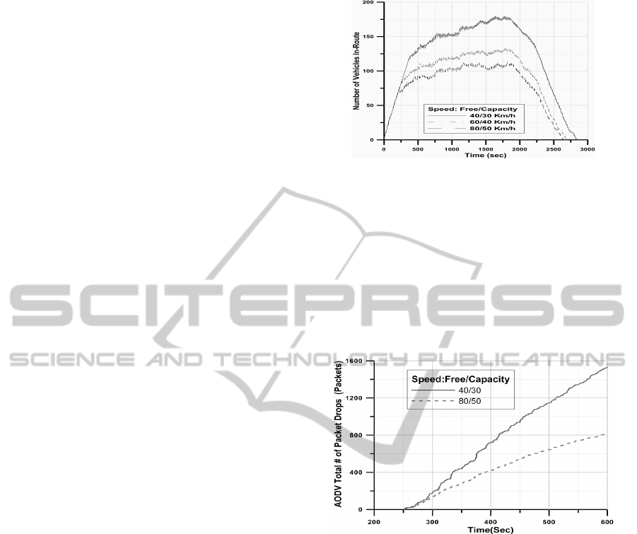
5.2 Number of Moving Vehicles in the
Network
The traffic simulation included three phases; two
transient and one steady-state phase. The loading and
unloading phases are transient phases, which represent
the two shoulders of the peak period, as illustrated in
the graphs in Figure 6. In the loading phase, vehicles
enter the road network, while in the unloading phase
vehicles exit. Between them there is a steady-state
phase in which some vehicles are entering the
network, while others are exiting. In the steady-state
phase, the change in the number of the vehicles in the
network is not significant. While in the loading phase
the network loading changes significantly. The length
of these phases depends mainly on the speed
distribution, vehicle departure rates, and the road map.
Figure 6 shows the number of vehicles in the network
for different speed parameters (Free/Capacity). The
importance of determining these phases is that during
the transient phases the communication network may
be spatially partitioned without data routes that link
these partitions together. While in the steady-state
phase vehicles almost cover the entire road network,
and most probably there is full connectivity between
vehicles. Consequently, the network communication
behavior during the transient phases is different from
that during the steady-state phase.
By controlling the speed parameters and the
departure rate distribution, we can control the network
partitions during the simulation time. Using this
methodology, we can model the delay tolerant
communication networks (DTN) (Fall 2003) and
intermittently connected mobile networks (Lindgren,
Doria et al. 2003).
Thirdly defining these phases gives us estimation
for the vehicle density in the network at any instant in
time. This density significantly influences the
communication performance as will be shown later.
Figure 6: Number of vehicles in the network.
5.3 FTP Connections and AODV
In this section some results obtained from the FTP
communication will be presented. As we described in
the previous subsection the vehicle density
significantly affects the communication performance.
Figure 7 shows the cumulative number of packets
dropped by AODV across the entire network due to
the loss of a route to the destination.
Figure 7: AODV total # of packet drops.
The AODV packet drop can be caused by two
main reasons: 1) the number of vehicles in the
network; the larger the number of vehicles the larger
the traffic. So any route missing will result in a larger
number of drops. 2) The vehicle speeds; the higher the
speed the faster the route changes, and so the larger
the number of packet drops.
In an attempt to identify which of the two factors
is more influential on the routing, Figure 8 illustrates
how the average number of drops vary across the
network. It shows that around 300 seconds, both
speeds have a similar average packet drop rate. During
this interval the number of vehicles for both scenarios
is very similar. While as the difference in vehicle
density increases with time, the average number of
drops also reflects the changes in traffic density.
VEHITS2015-InternationalConferenceonVehicleTechnologyandIntelligentTransportSystems
140
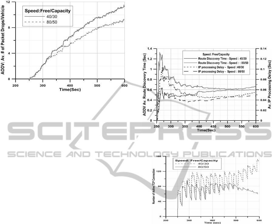
Figure 8: AODV Av. # of Packet Drops per vehicles.
The two figures demonstrate that for the two
scenarios, despite the fact that the vehicle density is
related to the traffic stream speed, the vehicle density
has a more significant impact on the performance of
the communication system. Consequently, a change in
the traffic stream density caused by other factors, such
as traffic demand has a more significant impact on the
routing than does changes in the traffic stream speed.
Another important parameter in routing efficiency is
the route discovery time which is shown in Figure 9.
It shows the correlation between the route discovery
time and the IP processing and queuing delay on the
vehicles. After 250 seconds each vehicle attempts to
establish an FTP session with the server resulting in a
flood of AODV route request packets. This flood
increases the amount of IP packets being sent and
processed at the IP layer in each vehicle, and thus
increases the IP processing (queuing + processing)
delay, which is reflected on the route discovery time.
From Figure 9, it is clear that the long route
discovery time when initiating the communication is
mainly due to the IP queuing and processing delay in
the higher density scenario. Subsequently, the TCP
congestion control logic paces the packets based on
the acknowledgements it receives. This pacing results
in lower queuing and processing delay. Consequently,
both the processing delay and route discovery time
gradually decrease.
Figure 10 illustrates the effect of the speed and
density on the number of active TCP connections on
the FTP server. The figure demonstrates that when
initiating the FTP connections there are 69 and 61 TCP
connections for the 40/30 and 80/50 speeds,
respectively. These numbers are proportional to the
number of concurrent vehicles in the network for each
scenario. The results also demonstrate that some of
these connections were completed before the start of
the second cycle (at 270 seconds). Similarly, the
second cycle increases the number of connections.
The results demonstrate that later the number of
connections for the 80/50 scenario decreases
significantly because some vehicles exit the network
and so their connections are timed-out and dropped,
while in the 40/30 scenario vehicles are still traveling
on the network.
Figure 9: AODV Av. route discovery time and Av. IP
processing delay.
Figure 10: Number of TCP connections of the FTP server.
The above results and analysis for the simple scenarios
we used are realistic and consistent with the protocol
behavior.
5.4 The System Scalability
The scalability is the most critical drawback of
existing platforms including the proposed platform.
The two main scalability parameters are the memory
usage and the execution time. The preliminary study
results show that the number of nodes and the data
traffic rate are key factors behind the scalability issue.
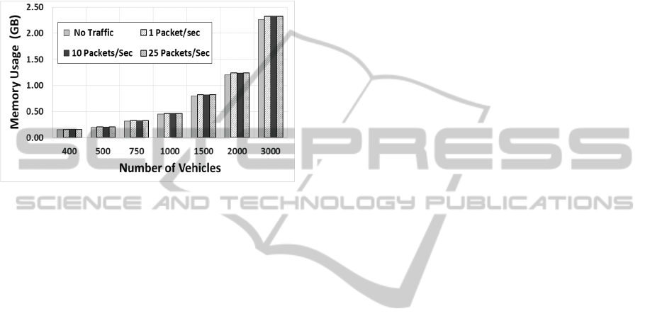
Specifically, results show that, the memory usage
grows exponentially with the number of vehicles in
the network, as shown in Figure 11. The result shows
also that the execution time is mainly dependent on the
traffic on the network.
This scalability problem is reasoned to the detailed
implementation of the network simulation models.
However, this detailed implementation is necessary
VNetIntSim-AnIntegratedSimulationPlatformtoModelTransportationandCommunicationNetworks
141
when studying the behavior of individual vehicles. In
case of focusing on global analysis, where the
individual vehicle’s behavior is not important, we can
reduce the number of vehicles in the network by reuse
the same vehicle. Thus the maximum number of
vehicles we need in the simulation network become
the maximum concurrent number of vehicles. To
achieve both advantages we enabled the vehicle reuse
option in the VNetIntSim.
Figure 11: The memory usage (GB) vs. the number of nodes
for different traffic rates.
6 CONCLUSIONS AND FUTER
WORK
In this paper we presented the VNetIntSim, an
integrated platform for simulating transportation and
VANET networks. VNetIntSim integrates a
transportation simulator (INTEGRATION) with a
data communication network simulator (OPNET
modeler). Results obtained from the simple scenarios
are realistic and consistent with protocol behavior.
The most important advantage of VNetIntSim is its
capability to fully simulate the two-way
interdependency between the transportation and
communication systems, which is necessary for many
applications. In addition it provides the power of both
simulators to study global network parameters as well
as very detailed parameters for in each system at a
microscopic level considering a 0.1 second
granularity. The most important challenge is the
simulation speed which is slow due to the number of
vehicles in the network.
In the future we will try to enhance the simulation
speed by creating a vehicle module with the necessary
sub-modules. Also we plan to implement the DSRC
module in the OPNET modeler. The most important
future work is to implement some applications for ITS
such as speed harmonization, eco-driving, congestion
avoidance and vehicles re-routing. We can also study
the effect of quality of services and different routing
mechanisms on the performance of the transportation
system and services offered for both users and
vehicles.
ACKNOWLEDGEMENTS
This work was made possible by NPRP Grant # 5-
1272-1-214 from the Qatar National Research Fund (a
member of The Qatar Foundation). The statements
made herein are solely the responsibility of the
authors.
REFERENCES
Alam, M., M. Sher and S. A. Husain (2008). VANETs
Mobility Model entities and its impact. 4th
International Conference on Emerging Technologies,
ICET. .
Baskar, L. D., B. De Schutter and H. Hellendoorn (2007).
Hierarchical Traffic Control and Management with
Intelligent Vehicles. Intelligent Vehicles Symposium.
Bruner, G. C., and A. Kumark (2007). "Attitude toward
location-based advertising." Journal of Interactive
Advertising 7(2): 3-15.
Choffnes, D. R. and F. E. Bustamante (2005). An integrated
mobility and traffic model for vehicular wireless
networks. Proceedings of the 2nd ACM international
workshop on Vehicular ad hoc networks, ACM.
Fall, K. (2003). A delay-tolerant network architecture for
challenged internets. Proceedings of the conference on
Applications, technologies, architectures, and protocols
for computer communications, Karlsruhe, Germany,
ACM.
Hafeez, K. A., Z. Lian, L. Zaiyi and B. N. Ma (2010).
Impact of Mobility on VANETs' Safety Applications.
Global Telecommunications Conference
(GLOBECOM 2010).
Hoque, M. A., X. Hong and B. Dixon (2014). "Efficient
multi-hop connectivity analysis in urban vehicular
networks." Vehicular Communications 1(2): 78-90.
Ibrahim, K. and M. C. Weigle (2008). ASH: Application-
aware SWANS with highway mobility. INFOCOM
Workshops.
Jiang, D., V. Taliwal, A. Meier, W. Holfelder and R.
Herrtwich (2006). "Design of 5.9 GHz DSRC-based
vehicular safety communication." Wireless
Communications, IEEE 13(5): 36-43.
Li, M., Z. Yang and W. Lou (2011). "CodeOn: Cooperative
Popular Content Distribution for Vehicular Networks
using Symbol Level Network Coding." IEEE J.Sel. A.
Commun. 29(1): 223-235.
Lindgren, A., A. Doria and O. Schel (2003). "Probabilistic
routing in intermittently connected networks."
VEHITS2015-InternationalConferenceonVehicleTechnologyandIntelligentTransportSystems
142

SIGMOBILE Mob. Comput. Commun. Rev. 7(3): 19-
20.
M. Caliskan, C. L., B. Scheuermann, M.Singhof "Multiple
Simulator Interlinking Environment for C2CC in
VANETs." http://www.cn.hhu.de/en/our-research/
msiecv.html Accessed Aug. 2014.
Mohammad A. Hoque, X. H., Brandon Dixon (2014).
"Innovative Taxi Hailing System using DSRC
Infrastructure." ITS World Congress, Detroit.
Perkins, C., E. Belding-Royer and S. Das (2003). "RFC
3561-ad hoc on-demand distance vector (AODV)
routing." Internet RFCs: 1-38.
Pigne, x, Y., G. Danoy and P. Bouvry (2010). A platform
for realistic online vehicular network management.
IEEE GLOBECOM Workshops (GC Wkshps).
Piorkowski, M., M. Raya, A. L. Lugo, P. Papadimitratos,
M. Grossglauser and J.-P. Hubaux (2008). "TraNS:
realistic joint traffic and network simulator for
VANETs." ACM SIGMOBILE Mobile Computing and
Communications Review 12(1): 31-33.
Rakha, H. (Accessed Aug. 2014). "INTEGRATION Rel.
2.40 for Windows - User's Guide, Volume I:
Fundamental Model Features." http://filebox.vt.edu/
users/hrakha/Software.htm#Integration 1.
Rondinone, M., J. Maneros, D. Krajzewicz, R. Bauza, P.
Cataldi, F. Hrizi, J. Gozalvez, V. Kumar, M. Röckl and
L. Lin (2013). "iTETRIS: a modular simulation
platform for the large scale evaluation of cooperative
ITS applications." Simulation Modelling Practice and
Theory 34: 99-125.
Roy, S., R. Sen, S. Kulkarni, P. Kulkarni, B. Raman and L.
K. Singh (2011). Wireless across road: RF based road
traffic congestion detection. Third International
Conference on Communication Systems and Networks
(COMSNETS).
Sommer, C., R. German and F. Dressler (2011).
"Bidirectionally Coupled Network and Road Traffic
Simulation for Improved IVC Analysis." Mobile
Computing, IEEE Transactions on 10(1): 3-15.
Talebpour, A., H. Mahmassani and S. Hamdar (2013).
"Speed Harmonization." Transportation Research
Record: Journal of the Transportation Research Board
2391(-1): 69-79.
Technology, R. (Accessed Aug. 2014). "http://
www.riverbed.com/products/performance-
management-control/opnet.html.".
Van Aerde, M. and H. Rakha (1995). Multivariate
calibration of single regime speed-flow-density
relationships. Proceedings of the 6th Vehicle
Navigation and Information Systems Conference.
Van den Broek, T. H. A., J. Ploeg and B. D. Netten (2011).
Advisory and autonomous cooperative driving systems.
Consumer Electronics (ICCE), 2011 IEEE International
Conference on.
Wang, S. Y. and C. L. Chou (2009). "NCTUns tool for
wireless vehicular communication network
researches." Simulation Modelling Practice and Theory
17(7): 1211-1226.
Xiao, Y., Q. Zhao, I. Kaku and Y. Xu (2012).
"Development of a fuel consumption optimization
model for the capacitated vehicle routing problem."
Computers & Operations Research 39(7): 1419-1431.
VNetIntSim-AnIntegratedSimulationPlatformtoModelTransportationandCommunicationNetworks
143
