
Some Tools for Aiding Teaching the Basics of Digital Electronics and
Signal Processing
Suvi Karhu, Jarmo T. Alander and Otto Nurmi
Department of Electrical Engineering and Energy Technology, University of Vaasa, Yliopistonranta 10, Vaasa, Finland
Keywords: Animation, Digital Electronics, Digital Signal Processing (DSP), Finite Impulse Response Filter (FIR),
Engineering Studies, Field Programmable Gate Array (FPGA), Hardware Design Languages (HDL),
VHDL.
Abstract: In this paper we describe some computing tools designed for aiding teaching of the basics of digital
electronics and its applications mainly in signal processing for university studies of engineering. In this
study we have developed two types of teaching tools: firstly, several small JavaScript-based simulation tools
for visualizing the basic functions of digital circuits and their hardware design language models, and
secondly, an FPGA-based FIR filter system for showing how to perform simple digital signal processing
tasks with FPGAs.
1 INTRODUCTION
One of the authors (J.A.) has been teaching digital
electronics in several courses in Finnish universities
for over thirty years. For these courses the author
has implemented some simulators using such
programming languages as Extended Algol, Simula,
VisualBasic, and C++. The idea has been to teach
the basics of functioning of digital circuits with
computers which allow detailed monitoring of the
events in digital circuits while eliminating totally the
many practical problems of physical circuits and
their monitoring. For most engineers and scientists it
is important to know the principles of digital
electronics, how typical circuits function and how
they can be combined together to create more
complex devices. If real circuit implementations are
needed, they are typically designed by experts of
digital electronics to whom the physical aspects of
circuits are naturally very well known. They also use
highly complex software not suitable for learning the
very basics of digital electronics.
Today the computer aided programming
approach itself is more or less enough when the
system or circuit is usually implemented on a
microcontroller, Programmable Digital Signal
Processor (PDSP), or Field Programmable Gate
Array (FPGA) circuits. Only a minimum amount of
knowledge of the physical aspects is needed, since
most of the design work is done using software.
Usually the hardware is ready to run without any
soldering or similar physical steps. FPGAs are not a
curiosity of digital electronics, but a class of devices
for the most challenging computational problems
encountered by as well engineers in industry as
scientists in university and research laboratories.
Therefore it is important that the future experts who
might need FPGAs in their projects get some basic
knowledge of this technology.
In our university we have concentrated on
FPGAs as the hardware realization of digital
devices. All the graduating students of engineering
get at least basic knowledge of FPGAs, while there
is also the possibility to concentrate on FPGAs
especially in signal processing applications at
Master’s level. Therefore it is important to give
students some very easy hands-on experimentations
during lectures and laboratory works of several
courses related to digital electronics and digital
signal processing (DSP).
In the field of signal processing, PDSPs
dominate due to their low price and suitability for
performing complicated algorithms (Meyer-Baese
2007: 12-13). However, nowadays some signal
processing algorithms are increasingly often run on
FPGAs. FPGAs are particularly good in front-end
applications, like Finite Impulse Response (FIR)
filters and Fast Fourier Transforms (FFTs)
(Donovan, 2002). Due to this trend, it is useful to
teach FPGA-based signal processing to the students
of basic DSP course.
193
Karhu S., T. Alander J. and Nurmi O..
Some Tools for Aiding Teaching the Basics of Digital Electronics and Signal Processing.
DOI: 10.5220/0005408501930201
In Proceedings of the 7th International Conference on Computer Supported Education (CSEDU-2015), pages 193-201
ISBN: 978-989-758-107-6
Copyright
c
2015 SCITEPRESS (Science and Technology Publications, Lda.)

Programming of FPGAs is considered challenging.
This is because of several reasons:
- FPGAs are digital hardware; therefore basic
knowledge of digital circuits is needed to understand
and use them.
- FPGAs are used by programming; basic
knowledge of programming is needed but is not
enough simply because of the parallel nature of the
circuits and their modeling languages. This
parallelism is usually totally absent from the
general-purpose programming languages like Java.
- The efficient use of parallel processing by
FPGAs presupposes understanding of pipelining,
which is usually not known by ordinary
programmers.
In this study we have developed two types of
teaching tools. Firstly, several small web-based
JavaScript simulation tools were created for
visualizing the function of digital circuits directly on
lecture slides. The idea has been to aid learning of
basics by providing very simple animations without
the need of more sophisticated simulation software.
Secondly, an FPGA-based FIR filter system was
developed for showing how to perform a simple
digital signal processing task with an FPGA device
and with the help of Matlab HDL Coder. Finally, as
an application of the audio system, a light organ was
designed as a student project using FPGA and a
Light Emitting Diode (LED) display made of
discrete components.
1.1 Related Work
Several software for simulating electronic circuits
exist. Those include i.a. SPICE for analog circuits,
Logisim for digital circuits and GNU Circuit
Analysis Package for mixed-signal (analog and
digital) circuits. These software are suitable when
doing homework and project work, but they are
usually not used during the lectures. Our idea is to
bring some visual aspect and interactivity to the
lectures by integrating some simulations to the
lecture slides. The hypothesis is that slides with
animated graphics improve learning when compared
to conventional, static lecture slides.
Since the learning of FPGA is time-consuming, it
is good if the student can study the subject also by
distance-learning. The idea of learning FPGA
programming in web environment has been utilized
in virtual and remote laboratories. A remote
laboratory is based on real hardware, while virtual
laboratories are based on software models. Our
simulation tools presented in this paper are neither
remote nor virtual laboratories, but suitable for
distance-learning because they are available via
Internet.
A proposal for remote laboratory is presented by
Drutarovský et al. (2009). Their system includes a
LabVIEW based measurement server, FPGA
development boards, logic analyzer, digital storage
oscilloscope and signal generator. Persiano et al.
(2007) propose a system through which users can
remotely control FPGA applications without
installing any development software to the
computer. The user can follow teaching and control
several measuring devices through a LabVIEW
based user interface. According to Soares et al.
(2011) in remote laboratories the challenge is the
interaction between the user and the hardware as a
realistic Internet-based interface. They implemented
an application using Hypertext Preprocessor (PHP)
which makes it possible to use Altera
®
DE2 board
and camera remotely. Multimedia and interactivity
have also been utilized by Quintans et al. (2005),
who have implemented a hypermedia application for
self-learning.
In the field of DSP, Hall et al. (2002) have
developed a framework which allows students to
combine their knowledge about DSP theory and
digital hardware design. They developed a Matlab
toolbox for sending and receiving data to and from
an FPGA device. The functions are useful in testing,
debugging and verifying the design. In addition, they
introduced a VHDL template, which contains all
needed testing infrastructure, and the students only
need to develop their own DSP module. Their
pedagogical principle was to start from small filters
and proceed to more complex DSP systems after the
students have understood the flow of the design
process. Later Hall et al. (2007) have also
emphasized the need of teaching fixed-point signal
processing, as the fixed-point solutions are often
faster, smaller, cheaper, and consume less power
than floating-point solutions. Haba (2014) suggests
that FPGA circuits can replace microcontrollers,
processors and other similar devices in the field of
digital signal processing. Reyes et al. (2009)
developed a FPGA-based DSP trainer for learning
Fourier transform, FIR filters, correlation and linear
convolution. The trainer was also able to generate
and acquire input signals and display the results on a
monitor.
2 WEB-BASED SIMULATIONS
The idea of our approach is to provide students with
study material that contains simple visual animations
CSEDU2015-7thInternationalConferenceonComputerSupportedEducation
194

on the basic components of digital electronics. The
hypothesis is that simple animations aid learning by
giving clear visual representation of the functions.
There are known problems with complex animations
that may even disturb learning by overloading
perception (Ainsworth, 2008). Here we assume that
simple animations have more positive than negative
effects on learning.
In order to keep things as simple as possible our
tools are separate and available via Internet not only
for the students of our university, but also for
anyone interested in digital electronics simulations.
Our simulations only demonstrate certain aspects of
digital electronics and implementation of hardware
using HDLs. They are not meant to replace any
more complex simulation software but to provide a
replacement for illustrations and show how the
function can be realized in various Hardware
Description Languages (HDLs) and styles (VHDL
architectures).
All lecture pages can contain emphasized words,
keywords, that are not only highlighted using html
<b>-tags but also used in a simple game, in which
the words are guessed like in the hangman game.
The material used in this game is also used in
weekly brief exams we call microexams so that the
student can use this feature for preparing to the
exams by drill learning key concepts of the lecture
material (Delazer et al., 2005).
Our simulations are implemented using
JavaScript, and they have been designed and tested
only with Mozilla Firefox. However, most of the
demos seem to work quite nicely at least also with
Google Chrome, perhaps because parts of them are
implemented with jQuery, a JavaScript library which
helps to avoid most browser incompatibilities.
Because the simulations are implemented in
JavaScript which is run on the client (student PC)
side and not on the server (university) side, there can
be in principle a nearly unlimited number of
concurrent users (students) without much computing
resource problems. This means that in future we can
easily increase the amount of similarly implemented
animations and other interactive material to our
lecture slides.
2.1 DigiAnilator
Our first tool presented here is called DigiAnilator.
To make the tool to be easily found on the Internet,
it was given a googleunique name, which means that
according to Google, it is not used on any other
webpage.
DigiAnilator
1
is able to simulate simple digital
circuits having up to 5 inputs and outputs. Thus it is
able to simulate gates or other simple circuits used in
digital circuits such as multiplexers and decoders.
The simulation is based on the truth table of the
circuit. The user can freely edit the truth table with
“Invert State” button to model any function of up to
5 variables he or she wants to simulate. The other
output of DigiAnilator gives the textual description
(program code) of the function in several HDLs and
variants of implementations, which in VHDL are
called architectures. When the user changes the
function to be simulated, the descriptions are
immediately updated. DigiAnilator uses a function
colour coding (the truth table) which was originally
shown in our earlier Java- and Visual Basic -based
digital circuit simulators (Alander et al., 1998).
2.2 AutoMagic
A human being is good at understanding and
remembering (learning) visual information. The
obvious problem in this respect when using any
modeling language, not only HDL, is that they
almost totally lack any graphical illustrations. This is
a big problem especially in teaching of digital
electronics basics, while the circuits are most
naturally represented by well established circuit
diagrams.
In order to show how the VHDL model is
running in parallel, another JavaScript-based web
application called AutoMagic
2
was implemented to
illustrate both the running of the HDL program and
the graphical presentation of the circuit and other
possible illustrations such as the truth tables.
AutoMagic provides a step-by-step simulation of the
model according to Gray-coded input sequence. In
addition the speed of the simulation can be
interactively controlled with arrow keys.
2.3 DSPAutoMagic
For demonstrations of DSP basics within web-based
lecture slides a simple DSP system called
1
http://lipas.uwasa.fi/~TAU/AUTO1010/demo/DigiAni
lator.html
2
Direct link:
http://lipas.uwasa.fi/~TAU/AUTO1060/slides.php?File
=3000Computer.txt&Page=27
If direct link does not work, go to page
http://lipas.uwasa.fi/~TAU/AUTO1060/slides.php?Mod
e=Printer&File=3000Computer.txt
and make a search: AND / VHDL.
SomeToolsforAidingTeachingtheBasicsofDigitalElectronicsandSignalProcessing
195

DSPAutoMagic
3
3
was implemented. The idea is to
combine all multimedia modes (graphics, image
both 2D and 3D, and audio) to interactively illustrate
typical signals, filters and their applications. The
system can be used both as a standalone webpage,
and as a part of another webpage. A simple event-
recording and playback system was implemented to
make it easy to automatically start a given
demonstration on a lecture slide without the need for
manual interactive setting of parameters.
3 FIR FILTER
DEMONSTRATIONS
Yuxi et al. (2010) suggest that with FPGA circuits
students can implement practical applications from
theoretical subjects along with design software like
Matlab. In addition to developing the web-based
simulation tools, we wanted to demonstrate FPGA-
based digital signal processing for students of a
bachelor level DSP course, and to introduce the use
of Matlab HDL Coder to facilitate the programming
process.
For this purpose we created an FPGA-based FIR
filter system, which was designed for filtering audio
signals. The students of the bachelor level DSP
course have no previous experience on FIR filters,
but they have studied one course of digital
electronics, which includes basic FPGA
programming with VHDL. The aim of this
demonstration is to present the students how to
perform a basic signal processing task with an
FPGA device.
The system included two filters, which we call
LargeFilter and SmallFilter. The first filter, which
we call LargeFilter, is designed to filter integer
signals with integer coefficients. The input is
convolved with 31 coefficients, and the result is
divided by 256. This filter was designed by
modifying the code from Meyer-Baese (2007: 179-
180). The input and output signals are sent to the
filter from Nios II processor, but the coefficients are
not programmable. The input and output are 16-bit
and 32-bit, respectively. Depending on the choice of
3
Direct link:
http://lipas.uwasa.fi/~TAU/AUTO1060/slides.php?File
=0000Intro.txt&Page=35
If direct link does not work, go to page
http://lipas.uwasa.fi/~TAU/AUTO1060/slides.php?Mod
e=Printer&File=0000Intro.txt
and make a search: DSP & Measurements.
coefficients, the filter can be either symmetric or
asymmetric. In this study we used a symmetric filter.
The second filter, which we call SmallFilter is
designed to filter fixed-point signals with fixed-point
coefficients. The input and output are both 14 bits
wide. The filter is symmetric and contains 8
programmable coefficients. The filter was generated
with Matlab HDL Coder.
3.1 Tools
The system was designed with the Development and
Education board DE2 of Altera
®
. The system
consisted of Nios II processor, audio codec,
SDRAM memory, switches and buttons. Nios II is a
soft processor which can be instantiated on an
Altera
®
FPGA board. Nios processor was
programmed using SOPC Builder of the Quartus II
10.1sp1 software and Nios Software Build Tools
(SBT) 10.1sp1 which is an Eclipse-based integrated
development environment (IDE) for Nios-specific
C/C++ code. The latter is an Eclipse-based
integrated development environment (IDE) for Nios-
specific C/C++ code. The former is the built-in
SOPC tool of Quartus, but is nowadays considered a
legacy tool because in newer Quartus versions it is
replaced with a more high-performance tool, Qsys.
Matlab
®
HDL Coder is a tool which is able to
create VHDL and Verilog code from Matlab
functions, Simulink models and Stateflow charts.
HDL Coder generates both synthesizable code for
programming FPGAs and testbenches for
simulation. Matlab code generation process is
executed with the help of Workflow advisor, which
offers the following actions (MathWorks
®
, 2014):
- Verify floating point design. Floating-point
design is the original Matlab code written by the
user. In this step the software simulates that code
and collects the minimum and maximum values for
all the variables. These results can later be compared
to the results of the simulation of the fixed-point
design.
- Run floating-to-fixed conversion. In this step the
original Matlab code is transformed into different
kind of Matlab code, which uses only fixed-point
numbers.
- Verify the fixed-point design. In this step we can
compare the outputs of floating- and fixed-point
codes. The results from fixed-point simulation can
later be compared with the results of the fixed-point
design.
- Generate HDL code.
- Simulate the generated HDL code. Here the code
can be simulated e.g. with ModelSim, and we see if
CSEDU2015-7thInternationalConferenceonComputerSupportedEducation
196
the results match with the results of the fixed-point
design.
- Synthesis and project creation. HDL Coder also
helps create an Altera
®
Quartus™ or Xilinx
®
ISE™
project with the selected options.
3.2 The System
The FPGA system was built around Altera
®
’s Nios
II processor. The Nios II system was connected to
one user peripheral - the audio codec Wolfson
WM8731 controller - and to some pre-designed
peripherals: parallel I/O (PIO) modules for the
buttons, switches and light-emitting diodes (LEDs),
Liquid Crystal Display (LCD) controller, on-chip
memory controller and an SDRAM controller. All
these modules used the Avalon Memory-Mapped
(MM) interface to communicate with the processor.
PIO modules had also the Interrupt Sender interface
and signals from the audio codec were exported to
the top level using Avalon conduit interface.
3.2.1 Audio Codec
WM8731 is a stereo codec device that has two pairs
of ADA (analog-digital-analog) converters: one for
both channels, left and right. The audio codec
controller VHDL files and the controller driver C
file were obtained from the textbook of Chu (2011).
WM8731 was first configured through I2C bus so
that the left and right headphone volumes were set to
0 dB and analog path was set to “microphone in”
with no boost. Default 48K sampling rate with 16-bit
samples and 12.288 MHz master clock was used.
3.2.2 Memories
The application used two memories: the on-chip
memory of the FGPA device and an external
SDRAM memory module. The on-chip memory of
the EP2C35 FPGA is organized in 105 M4K blocks.
However, in this work we needed only a small on-
chip memory, and thus its size was set to 16 Kbytes.
Communication was performed using 32-bit words,
which is the recommended wordlength when
connecting the on-chip memory to the data master
port of the processor (Altera
®
, 2010).
The SDRAM memory module located on the
DE2 board can store 8 MiB of data. It is meant for
storing large blocks of data, for example audio data
(Altera
®
, 2010). The communication between the
system and memory module was performed using
the pre-designed SDRAM controller provided by the
SOPC Builder. In addition to this, a phase-locked
loop (PLL) was needed to clock the SDRAM
module. The purpose of the PLL circuit is to
generate a clock signal which is suitable for the
SDRAM. That clock must be phase-shifted by -3ns
from the original clock source, as described in
Altera
®
’s (2008) tutorial. The ALTPLL module of
the SOPC Builder software did not work, but the
problem was solved by using an ALTPLL
megafunction instead of ALTPLL Nios module. The
megafunction was inserted to the top-level
schematic diagram and the inputs and outputs were
connected to the appropriate pins.
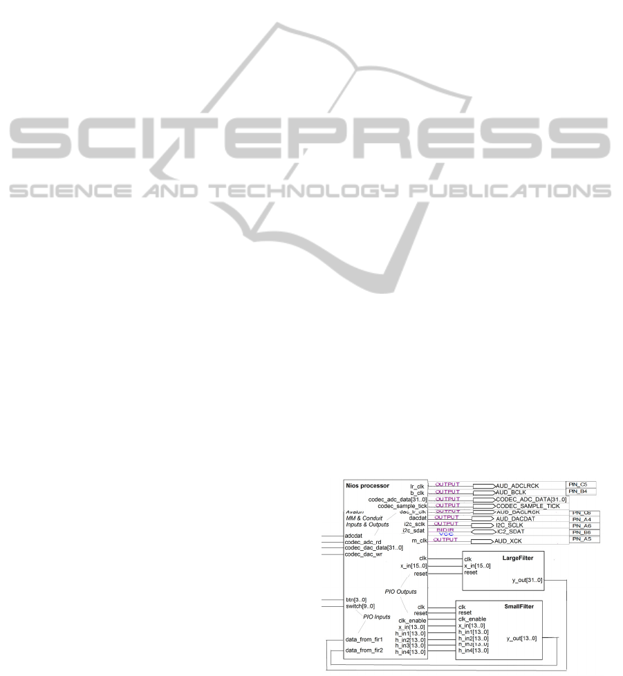
3.2.3 Instantiation of the Nios System
VHDL files of the SOPC system were generated and
a block diagram file (BDF) was generated from the
VHDL files. The BDF file was then used to create
the top-level schematic diagram file (Fig. 1). A PLL
megafunction block was inserted to the top-level
diagram file, as well as the power source for the
LCD. The pins were assigned by using the Comma-
Separated Values (CSV) file from the DE2 system
CD. The maximum operating frequency of the
system was set to 50 MHz, which was the frequency
of the system clock signal.
3.2.4 Filters
The filters could have been integrated inside the
Nios system in the same way as the audio codec
controller: by writing an Avalon-compatible
wrapping circuit around the filter component.
However, we used a less time-consuming approach
and placed the FIR filters outside the Nios system
and connected them to the Nios system with PIO
modules. The input data could then be sent to the
filter by writing it to the appropriate PIO register,
and similarly the filtered data was acquired by
reading the PIO register.
Figure 1: Part of the top-level schematic diagram of the
FIR audio system.
SomeToolsforAidingTeachingtheBasicsofDigitalElectronicsandSignalProcessing
197
3.2.5 Testing
The filters were first tested with an impulse signal,
which consisted of 199 zeroes and a one in the
middle. This simple test reveals if the filter has some
serious problem in it. For this type of input signal
the filter should return its own coefficients. In our
first test, the filter returned the sum of its
coefficients. This error was due to problems in clock
rate. After fixing the clock rate, the response was
correct.
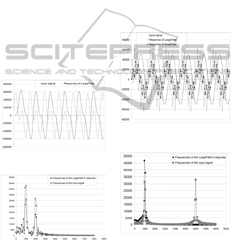
Next, FIR filtering of a real audio signal was
tested. The filters were designed to filter away all
frequencies above 1000 Hz. We used an input signal
which was a sum of 1000 Hz and 2000 Hz
frequencies (Fig. 2 and Fig. 3). The test was
performed on both filters. The result of the
LargeFilter showed that the frequency of 2000 Hz
was clearly attenuated (Fig. 2 and Fig. 3). The
response of the SmallFilter was also correct, but the
change in the signal was only small due to the low
order of the filter, and thus the signal is not shown
here.
Figure 2: The harmonic input signal (grey) consisting of
sine waves at 1000 Hz and 2000 Hz and the response of
LargeFilter (black) to the input signal.
Figure 3: The frequency spectra of the input signal (grey
squares) and the LargeFilter’s response (black diamonds).
However, this signal consisted only of harmonic
frequencies. Next, a signal consisting of non-
harmonic frequencies was tested. We used a signal
which was a sum of 1000 Hz and 5678 Hz
frequencies. The generation of the signal was
complicated, and thus not exactly the correct shape
for the signal was obtained, but an approximation
accurate enough was created (Fig. 4 and Fig. 5).
Both LargeFilter and SmallFilter were tested.
The results showed that the LargeFilter removed the
frequencies above 1000 Hz completely (Fig. 4 and
Fig. 5), whereas the SmallFilter removed them only
partially due to the low order of the filter (Fig. 4 and
Fig. 6). Both results were proved correct when
verified with equivalent Matlab filters.
Figure 4: The non-harmonic input signal (grey) consisting
of frequencies of 1000 Hz and 5678 Hz, the LargeFilter’s
response (black) and the SmallFilter’s response (black
circles).
Figure 5: The frequency spectra of the non-harmonic input
signal (grey squares) and the LargeFilter’s response (black
diamonds).
CSEDU2015-7thInternationalConferenceonComputerSupportedEducation
198
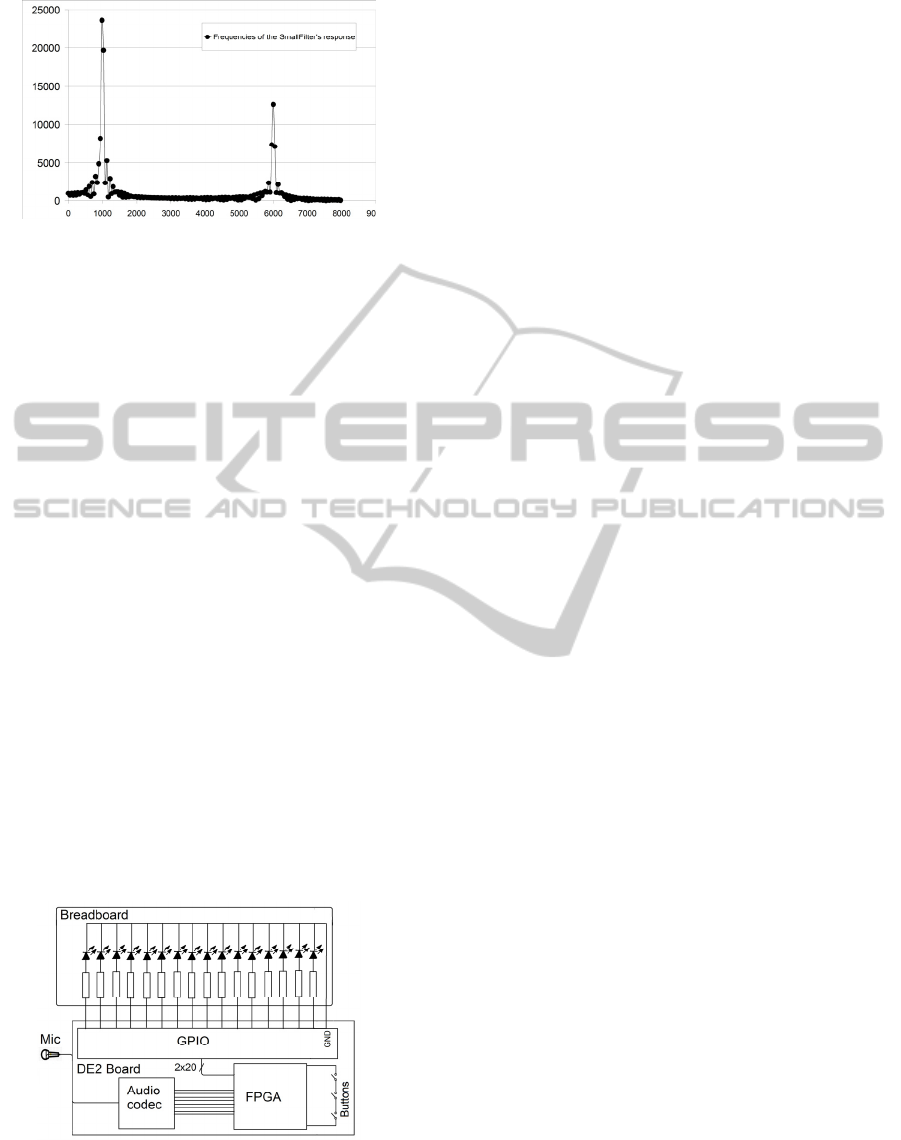
Figure 6: The frequency spectrum of the SmallFilter’s
response (black circles).
3.3 Experiments with Students
The filter system was demonstrated for the students
of our bachelor level DSP course. The frequencies of
1000 Hz and 5678 Hz were used. The change of the
signal was clearly audible, and the differences
between the filters were understood. The benefits of
using Matlab HDL Coder for facilitating FPGA
development were presented. To further improve the
demonstration, the generation of the plots should be
made more automatized.
Later in the course the students were given a task
to implement a light organ as a project work of the
course (Fig. 7). The students had to build a column
of LEDs and resistors on a breadboard, and to
develop and include a Pulse Width Modulation
(PWM) module to a predesigned Quartus project.
Although we used a different design than the system
presented in this paper, the contents of it were
similar excluding the Nios processor and the FIR
filters. Thus the demonstration described here was
probably helpful in implementing the task. The
predesigned project included a functionality to
adjust the number of LEDs shining according to the
volume, and the students’ task was to control the
brightness of the LEDs with the PWM module.
Figure 7: The circuit diagram of the light organ project
work.
Some students had problems modifying the
project and adding the module to the system. This
suggests that a Nios-based approach might be more
suitable for similar tasks because connecting
modules through PIO is easy with it. Also using a
block diagram file (BDF) instead of a textual, i.e.
HDL-based, description on the top level of the
design would help the students to understand the
structure of the design and to make modifications to
it.
A feedback survey was carried out in the last
project work tutorial. 15 students (~50 % of the
participants) answered to the survey. The feedback
survey consisted of seven multiple choice questions
and three written questions. The answers of the
multiple choice questions showed that learning the
programming of FPGA is considered useful but
difficult (Table 1). Seemingly the simulations and
animations have not yet influenced much on the
students’ opinion on the usefulness of the lectures,
but better results can be expected later when the
amount of simulations increase, students get more
familiar with them and all of their advantages will be
fully exploited.
4 DISCUSSION
Visual perception and feedback is most natural to
humans. This also applies in engineering studies
including digital electronics and systems studies.
Interaction is definitely increasing in computer
aided teaching in many ways. The contemporary
computer game student generation will probably
welcome also more entertaining computer game
approaches within more traditional study material. In
this work we have implemented a very simple
keyword drilling game approach originally designed
for weekly exams that we call microexams. This
could be made not only more vivid and entertaining
but more fit to learning by drill.
In our university engineering studies have the
following master level main subjects: automation
(A), computer science (C), electrical engineering
(EE), energy technology (ET), and
telecommunications (T), which are grouped in to
two programs for bachelor level studies: ACT and
EE&ET. However, the curricula are planned so that
the students have as much basic studies in common
as possible. Thus the contents of the basic courses
should be such that they support the studies of all
these branches of engineering. Therefore the
simulations also contain topics more or less relevant
not only to digital electronics and its application but
also electrical engineering, energy technology,
computing in general and data transmission devices.
SomeToolsforAidingTeachingtheBasicsofDigitalElectronicsandSignalProcessing
199

5 CONCLUSIONS
In this work we have described some simple
multimedia and hardware tools designed for aiding
the teaching of basics of modern digital electronics
circuits and implementation by programming FPGA
circuits. Many of our simulation tools are based on
web technology and are available via Internet. The
FIR system, on the contrary, runs on an FPGA board
along with a PC, and is aimed for demonstrating
FPGA-hardware-based digital signal processing and
introducing the code development process with a
HDL coder.
5.1 Future
Our examples are related to understanding the basics
of digital electronics and signal processing for the
design (engineering) of applications. In practise it is
important not only to understand the intended
correct behaviour but also verify that the
implemented designs fulfil specifications, which is a
challenging task for any more complex designs. Our
future plans include tools for this verification and
test phase using soft computing and especially
evolutionary algorithms based test automation
(Mantere et al., 2005).
It seems that pipelining, which is essential when
implementing powerful computation systems on
FPGAs, is not fully understood by programmers
having pure software development background.
Therefore our plans for future simulation tools
include also presentation and modeling of basic
pipelining architecture for efficient use of digital
logic.
Table 1: The results of the survey. Notations: SD=Strongly
Disagree, D=Disagree, N=Neutral, A=Agree, SA=Strongly
Disagree.
Statements
Percentage of students
SD D N A SA
I understand the theory of
PWM
20 20 20 33 7
I can program PWM with
VHDL
20 27 40 13 0
I understand the theory of
I2C bus
46 47 7 0 0
I can use the ready
programmed I2C code
33 47 13 7 0
Lectures helped me to
learn digital technology
0 27 60 13 0
Exercises helped me to
learn VHDL programming
0 13 0 74 13
Understanding FPGA
technology is useful
0 13 20 40 27
For embedded systems and SoC we plan to
replace Nios by ARM IP core, which gives potential
to use a large variety and volume of software
together with reconfigurable hardware for intensive
computing.
ACKNOWLEDGEMENTS
The authors acknowledge the Regional Council of
Ostrobothnia (project Teho-FPGA-I) which funded
the project. Anonymous referees are acknowledged
because their critique helped to clarify the
pedagogical motivation and ideas of the paper.
REFERENCES
Ainsworth, Shaaron, 2008. How do animations influence
learning? In Recent Innovations in Educational
Technology that Facilitate Student Learning, Daniel
H. Robinson (ed.), Information Age Publishing Inc.
Alander, J.T. & Salo, M., 1998. Digitaalisten piirien
yksinkertainen graafinen simulaattori DIGI [DIGI: a
simple graphical simulator of digital circuits]. In:
Tuntematon tietoyhteiskunta? Interaktiivinen
teknologia koulutuksessa [Proceedings of the Finnish
Conference on Interactive Computing in
Pedagogics], p. 106, Varpu Kuuliala & Elina Suojoki
(eds.), Hämeen kesäyliopisto, Hämeenlinna.
Altera (2010). Embedded Design Handbook.
http://www.altera.com/literature/hb/nios2/edh_ed_han
dbook.pdf.
Altera (2008). Using the SDRAM Memory on Altera’s
DE2 Board with VHDL Design.
ftp://ftp.altera.com/up/pub/Altera_Material/10.1/Tutori
als/VHDL/DE2/Using_the_SDRAM.pdf.
Chu, Pong P., 2011. Embedded SoPC Design with Nios II
Processor and VHDL Examples. John Wiley & Sons.
New Jersey.
Delazer, M., Ischebeck, A., Domahs, F., Zamarian, L.,
Koppelstaetter, F., Siedentopf, C.M.L. Kaufmann, L.,
Benke, T., Felber, S., 2005. Learning by strategies and
learning by drill. NeuroImage 25:3, 838–849.
Donovan, J., 2002. The truth about 300mm.
http://www.eetimes.com/document.asp?doc_id=11452
96.
Drutarovský, M., Šaliga, J., Michaeli, L., Hroncová, I.,
2009. Remote laboratory for FPGA based
reconfigurable systems testing. XIX IMEKO World
Congress Fundamental and Applied Metrology, pp.
54–58.
Haba, C.-G., 2014. Using FPGA development boards for
multi-course laboratory support. In EDUCON, Global
Engineering Education Conference, April 2014, pp.
794–797. IEEE.
Hall, T.S., Anderson, D.V., 2002. From algorithms to
CSEDU2015-7thInternationalConferenceonComputerSupportedEducation
200

gates: developing a pedagogical framework for DSP
hardware design. Digital Signal Processing Workshop,
2002 and the 2nd Signal Processing Education
Workshop. Proceedings of 2002 IEEE 10th, 157:161,
pp. 13–16.
Hall, T.S., Anderson, D.V., 2007. Teaching Hardware
Design of Fixed-Point Digital Signal Processing
Systems. Proceedings of the 2007 American Society
for Engineering Education Annual Conference &
Exposition. ASEE.
Mantere, T., Alander, J.T., 2005. Evolutionary software
engineering, a review. Applied Soft Computing 5:3, pp.
315–331.
MathWorks
®
, 2014. Basic HDL Code Generation with the
Workflow Advisor.
http://www.mathworks.se/help/hdlcoder/examples/bas
ic-hdl-code-generation-with-the-workflow-
advisor.html.
Meyer-Baese, U., 2007. Digital Signal Processing with
Field Programmable Gate Arrays. Springer. Berlin,
3
rd
edition.
Persiano, G.V., Rapuano, S., Zoino, F. Morganella, A.,
Chiusolo, G., 2007. Distance Learning in Digital
Electronics: Laboratory Practice on FPGA. In
Instrumentation and Measurement Technology
Conference Proceedings, 2007. IMTC 2007. pp. 1–6.
IEEE.
Reyes, R.S., Oppus, C.M., Monje, J.C.N., Patron, N.S.,
Gonzales, R.A., Fajardo, J.T.B., 2009. FPGA-Based
Digital Signal Processing Trainer, Computer Science
and Information Engineering, 2009 WRI World
Congress on, pp. 343–347.
Soares, J., Lobo, J., 2011. A Remote FPGA Laboratory for
Digital Design Students. In 7th Portuguese Meeting on
Reconfigurable Systems (REC 2011), Feb 2011, pp
95–98.
Yuxi, Z., Li, K. Jun, W., Jinping S., Zulin, W., 2010.
Methods and experience of using Matlab and FPGA
for teaching practice in digital signal processing. In
Education and Management Technology (ICEMT),
2010 International Conference on, pp. 414–417.
Quintans, C., Valdes, M.D., Moure, M.J., Fernandez-
Ferreira, L., Mandado, E., 2005. Digital electronics
learning system based on FPGA applications. In FIE
'05, Frontiers in Education, 2005. Proceedings 35th
Annual Conference, pp. S2G–7.
SomeToolsforAidingTeachingtheBasicsofDigitalElectronicsandSignalProcessing
201
