
Mapping Formal Results Back to UML Semi-formal Model
Vinicius Pereira
1
, Luciano Baresi
2
and Marcio E. Delamaro
1
1
Instituto de Ciencias Matematicas e Computacao, Universidade de Sao Paulo, Sao Carlos, SP, Brazil
2
Dipartimento di Elettronica e Informazione, Politecnico di Milano, Milan, MI, Italy
Keywords:
UML, Formal Results, Traceability, Mapping, Model Verification.
Abstract:
UML is a widely used modeling language and it has a semi-formal notation that helps the software developers
with a set of modeling rules, but without the need to have expertise in formal methods. This semi-formalism
encourages the use of UML in Software Engineering domain because the software engineers involved can
understand UML diagrams easily. Whereas, formal methods are more accurate than UML and their formal
models have a higher correctness than the UML models. Thanks to this correctness, over the years, researchers
are seeking ways to assign a formal semantics to UML. Usually they focus on how to formalize UML diagrams,
transform them into formal models (such as LISP) and use them in model checkers. However, few researches
discuss the problem of how to present the formal results to an audience who has no knowledge of formal
methods. In order to fulfil this problem, in this paper is presented a mapping responsible for making the
correlation between the formal results and the UML semi-formal environment, allowing the developer to
analyze the results without having advance knowledge of formal methods. Therefore, we hope that this work
may contribute to the increased adoption of formal methods in the software development industry.
1 INTRODUCTION
Unified Modeling Language (UML) (Eriksson et al.,
2004) is widely recognized and used in different
computational domains, being the modeling language
most adopted by the industry (Hutchinson et al.,
2011). The modeling of a system using UML
can be understood without problems among people
working in software development. Such degree
of understanding is possible because UML has a
semi-formal notation. This notation encourages
intercommunication among professionals without
expertise in real formalism.
The lack of a well-defined formalism in UML
makes its models less accuracy than a formal model.
This lowest accuracy could be reflect later in an
incomplete system. Depending on the system, it
could be impossible or unfeasible to repair it. For
example, a Web system can be repaired without major
problems, but not a critical embedded system. On the
other hand, the use of formal methods is not trivial. To
one uses these methods is necessary to have a certain
level of knowledge about formalism that the majority
of professionals that works with UML do not have.
Therefore, researchers seek ways to bring together the
UML and the correctness of formal methods.
Thus, assigning a formal semantics for UML
includes works that show how to add formalism to
UML, transform the formalized UML model in a
compatible model to be input for a model checker,
and to obtain the formal results that show whether
the modeled system satisfies or not the properties
desired by developers or stakeholders. Among these
proposals are the fUML
1
and studies that deal with
the formal semantics of at least one UML diagram
(Diethers and Huhn, 2004; Rossi et al., 2004;
Snook and Butler, 2006; Bouabana-Tebiel, 2009;
Grobelna et al., 2010; Micskei and Waeselynck, 2011;
Kaliappan and Konig, 2012).
However, these formal results continues with a
problem: an average professional in the Software
Engineering domain might not be able to either read
or analyse the output generated by model checkers,
due to the difficulty of the formalism present in the
results. Few researches deal with this problem, as for
example the study of (Mayerhofer et al., 2012).
To fulfil this limitation, (Baresi et al., 2012)
proposed the formalization of a subset of UML 2.x
models for the development of critical embedded
systems. Called MADES UML, this subset is part
1
http://www.omg.org/spec/FUML/Current
320
Pereira V., Baresi L. and Delamaro M..
Mapping Formal Results Back to UML Semi-formal Model.
DOI: 10.5220/0005372603200329
In Proceedings of the 17th International Conference on Enterprise Information Systems (ICEIS-2015), pages 320-329
ISBN: 978-989-758-097-0
Copyright
c
2015 SCITEPRESS (Science and Technology Publications, Lda.)

of a larger research effort carried out in the MADES
European project (Bagnato et al., 2010). MADES
UML uses TRIO (Ciapessoni et al., 1999) to assign
formal semantics to its subsets and the Zot
2
model
checker (Pradella et al., 2007) to analyze the union
between these models and TRIO.
In this context, we along with the MADES team
have proposed a contribution to the MADES UML
and deals with the problem of how analyze and use
results obtained by the model checker. For this
purpose, we present a mapping to support this activity
to trace information contained in the results and
include them within the UML model.
We claim that by means of our mapping, it is
possible to correlate the formal results’ information
(trace) — such as timestamp, state, transition, lifeline,
class, etc. — and the UML model, previously created
with a modeling tool. Once the mapping is done, the
developer might analyze which elements of the UML
model are present in the trace, where the error is —
if the result is unsatisfied — and when it occurred.
The debug process, where a developer can follow the
code during runtime and see what is happened with
the program, inspires such process. In our case, the
developer will follow the formal results by seeing
what is happening in the UML model. A support
tool, integrating our mapping with Eclipse IDE
3
is
also shown.
This paper is structured as follows: Section 2
describes the related works. Section 3 describes
the developed traceability technique and Section 4
details how works our mapping, which is responsible
for link the UML 2.x model and the formal results.
Section 5 there is a brief explanation of the possible
transformations that formal results might have in the
UML model. Section 6 presents an example of how
the traceability technique and its mapping operate.
Section 7 describes the lessons learned during this
study. Concluding remarks and future works are made
in Section 8.
2 RELATED WORKS
The major of reseachers that assign a formal
semantics to UML focus only on a single type
of diagram and neglect the integration of different
modeling elements. Well-known formalization of
types of single diagrams refer to Sequence Diagrams
(Storrle, 2003; Lund and Stolen, 2006; Micskei
and Waeselynck, 2011), State Machines (Paltor and
2
http://home.deib.polimi.it/pradella/Zot/
3
http://eclipse.org/
Lilius, 1999; Hammal, 2005) and Activity Diagrams
(Borger et al., 2000; Cengarle and Knapp, 2005;
Eshuis, 2006; Bouabana-Tebiel, 2009) as can be
seen in Table 1, where column SD stands for Single
Diagram.
Table 1: Related Works comparison.
Paper SD MD 1w 2w
(Paltor and Lilius, 1999)
(Borger et al., 2000)
(Storrle, 2003)
(Hammal, 2005)
(Cengarle and Knapp, 2005)
(Eshuis, 2006)
(Lund and Stolen, 2006)
(Bouabana-Tebiel, 2009)
(Micskei and Waeselynck, 2011)
x - x -
(Saldhana and Shatz, 2000)
(Diethers and Huhn, 2004)
(Broy et al., 2006)
- x x -
(Goldsby et al., 2006)
(Mayerhofer et al., 2012)
x - - x
(Remenska et al., 2013)
MADES UML + This study
- x - x
Considering the multi-diagrams (MD in Table 1)
UML models, the number of proposals is limited.
Among them, one can find UML Semantics Project
(Broy et al., 2006) working with Activity, State,
and Interaction Diagrams; the Vooduu approach
(Diethers and Huhn, 2004) which works with State
and Sequence Diagrams; and (Saldhana and Shatz,
2000) works with State and Collaboration Diagrams.
All works mentioned so far have an “one-way”
process of transforming the UML (and its semantics
assigned) to a different notation that can be
interpreted by formal verification tools (1w in
Table 1). On the other hand, finding a study that
shows the opposite — proposes a technique that takes
the formal results and transforms them to be displayed
in UML model (“two-ways”, in Table 1 as 2w) —
is more difficult, because the studies usually stop by
the results provided by model checkers. They do not
show how developers could analyze these results.
About researches that deals with both
transformation (2w), the study of (Goldsby et al.,
2006) is an example of how might be possible to
show formal results’ information to developers. They
use model checking in State Diagrams and then
present the formal results in a Sequence Diagram.
Another example is the work of (Mayerhofer et al.,
2012), which shows how to create an extension of
the fUML and both transformations using a dedicate
trace. Despite being interesting, the process presented
by them can be applied only with Statecharts. Note
that both studies deal with only one UML diagram.
Compared to these studies, MADES UML is a
multi-diagrams, currently assigning formal semantic
to five types of UML diagrams. The research
MappingFormalResultsBacktoUMLSemi-formalModel
321

Figure 1: Relationship among MADES UML steps.
presented here aims to add in MADES UML the
ability to present the formal results in the semi-formal
UML model built with its five diagrams. Thus, as
reported in the last line of the Table 1, the MADES
UML is multi-diagram and now owns a “two-way”
transformation, being able to show the formal results
back to the UML model.
The study of (Remenska et al., 2013) is similar
to the one present in this paper. They present a
multi-diagram approach that uses Sequence Diagram
to model the system and Activity Diagram to extract
concurrency information. The authors present both
transformations, but the way they present the formal
results is different from what is proposed here. In
their study, the formal results are displayed in a new
model, also created using only Sequence Diagrams.
In our study, the formal results are present in the
“original” UML model itself, i.e. we use the same
model that was created before the formalization. By
doing this, we can use all the diagrams in the model
to interact with the user. In fact, the debug process
was the inspiration here. Instead of running the
code and systematic follow what is happening during
execution, here the user follows the trace “execution”
and sees in the model — through highlights of UML
elements — what the model checker tried to do and
where it failed.
3 TRACEABILITY TECHNIQUE
While the process of assigning a formal semantic
to UML is relatively well explored, the reverse
process is not widely discussed. This paper proposes
this reverse process for MADES UML, by using a
mapping that allows the traceability of formal results
back into the UML model. As can be seen in
Figure 1, MADES UML is divided into three steps: (i)
Modeling, (ii) Transformation, and (iii) Verification.
Each step is described below.
Modeling. This step involves the creation of
an UML model with MADES UML semantics.
In order to create this model, it is used Papyrus
Modeling Editor
4
, the official UML2 graphical
modeler within Eclipse IDE, which provides the
UML syntax. Together with Papyrus, it is used an
UML Profile especially developed for MADES UML,
which provides its semantics.
Transformation. Herein it is performed a
transformation of UML model into a LISP script,
by using a support tool called CorrettoUML (Motta,
2012b). CorrettoUML was developed as a plug-in
for Eclipse IDE. This tool was developed to bring
together the UML model (and MADES UML
semantics) with the model checker.
Verification. This step involves running Zot model
checker with the LISP script. Zot was chosen because
it can undestand TRIO syntax used in MADES UML.
After the execution, the user should analyzes the
formal result to check for possible problems.
Throughout this paper we have devised a running
example. The chosen example is a car collision
avoidance system (CCAS). The CCAS example is one
of the case studies provided by industrial partners
of the MADES European Project
5
(Motta, 2012a).
The CCAS system analyzes the distance between a
car A and car B, with car A behind car B. If the
distance between them is less than the minimum
distance allowed for a period of time, then the car
A system slows it automatically until the minimum
distance between them is respected again. Based on
4
https://www.eclipse.org/papyrus/
5
http://www.mades-project.org/
ICEIS2015-17thInternationalConferenceonEnterpriseInformationSystems
322

this scenario, a MADES UML model was created
with eight diagrams contain Class, Object, State,
Sequence, Interaction and Time Property Diagrams
— the last one created for write the properties that
user want to analyze.
To developed the mapping between formal results
and UML model, we analyze the support tools
provided by MADES UML and the formal results
generated by Zot. The Figure 2 shows an example
of CCAS’ formal results. The formal results’ data
presented in Zot trace is not trivial for understanding.
An expert must analyze it line by line and manually
control where the information is going in the UML
model. This is an error prone activity. In order
to assist an expert we have created a traceability
technique that uses our mapping. Also a support tool
is under development
6
.
Figure 2: Example of formal results generated by Zot.
The traceability technique aims to add a fourth
step to the MADES UML: (4) To enable the analysis
of information contained in formal results within the
UML model that was previously transformed, i.e., the
transformation from “formal to UML model”. The
formal information should be represented in UML
diagrams, so it might be understandable to the user
who does not have (or have few) knowledge about
formal verification, formal methods, model checkers,
etc. The Figure 3 presents how our fourth step interact
with MADES UML.
As can be seen in Figure 3, the traceability
technique contains its support tool which includes
two elements: the Mapping Checker and the
Graphical Transformation Builder. Mapping Checker
is responsible to make the correlation between formal
and UML elements. Graphical Transformation
Builder performs transformations in the UML model
to represent each line in formal results inside the
UML model. More information about Mapping
Checker and Graphical Transformation Builder can
be found in Sections 4 and 5 respectively.
The technique also contains three artifacts. The
first one is the UML model created with MADES
UML semantics. The next one is our mapping, which
it is created when CorrettoUML transform the UML
6
https://bitbucket.org/vinpereira/tracetool
Figure 3: Traceability Technique and MADES UML.
model to the LISP script. New methods were created
in CorrettoUML to make it possible create a mapping
having information about both UML elements and
their formal equivalent. Finally, the last element is
the formal results generated by Zot.
The first task of the technique is identify the
elements present in formal results. From them, by
using the mapping, the traceability technique can
move forward and backward through each time node
within the results. Each of these nodes has one or
more formal element that was previously transformed
by CorrettoUML.
Next, the formal element can be one of the
following eleven different types of UML elements
identified on the five diagrams supported by MADES
UML: State Diagram - State or Transition; Sequence
Diagram - Lifelines, Message or Parameter; Class
Diagram - Class, Attribute or Operation; Object
Diagram - Object; and Interaction Overview Diagram
- Actions or Control Flows.
Therefore, the element is analyzed and the formal
element is mapped to its correct UML element
(one of eleven above). Finally, through the UML
element the traceability technique can access its UML
diagram and shown the formal results in the graphical
representation.
The main artifact is the mapping, for the reason
that without it, becomes unfeasible knowing how the
connection between formal and UML elements. With
that in mind, it is necessary to define what should be
present in the mapping and how it will be used by the
traceability technique.
MappingFormalResultsBacktoUMLSemi-formalModel
323

4 FORMAL TO UML MODEL
MAPPING
To create the mapping, we assume that when doing
the formal verification of the model, the user only
have access to UML model and formal results.
Thus, a third artifact is required to unite these
two types of environments. In order to make
such union, we foresee a mapping that contains
information that correctly identify the elements in
both environments. In addition, this information must
show that an element X in the formal environment
has its equivalent in an element Y in the semi-formal
environment.
The file that contains the mapping is defined as
a file with inputs which can be assigned without
major problems and extensible for future works in
expansion to others tools — for example, MADES
UML could uses another formal verification tool than
Zot. The file is created in Trans f ormation step
(see Section 3) when CorrettoUML is performing its
actions, because this is the best moment for gather
useful information about both modeling and formal
environment. Thus, when running CorrettoUML,
besides performing its pre-defined functions, the
tool is upgraded to be responsible for gathering the
information that we need to use our technique.
CorrettoUML’s upgrade involves creation
of methods that capture — at the moment of
transformation — information considered important
for the right correspondence between the modeling
and formal environments (see pseudo code in
Algorithm 1).
Algorithm 1 shows the core idea of collecting the
required data from State Diagrams for our mapping.
As CorrettoUML make the transformation from UML
model to formal model, our method gather the ID
and formal name for each element inside the State
Diagram (Lines 2 to 13). At Line 2, the method iterate
with each StateDiagram present in the UML model
created with MADES UML semantics. In Lines 3
to 7, our method manipulate all states inside a State
Diagram. At Line 3, our method gather each State
in the State Diagram. Then, in Line 4 the method
instanciate a CorrettoState (a semantic version of
State, for MADES UML) with the given state. Line 5
also instanciate a variable, now a Predicate one that
holds the TRIO temporal logic information for the
state. Finally, both ID and formal name are written
in the mapping file, as can be seen in Line 6, in order
to be used later in the traceability technique. The ID
cames from the UML state and the formal name is
gather from the Predicate’s name, since the formal
model created by CorrettoUML uses TRIO
Input: MADESModel madesModel, File
mapping
1 begin
2 foreach StateDiagram std in
madesModel.getStateDiagrams() do
3 foreach State state in std.getStates()
do
4 CorrettoState cstate = new
CorrettoState(state);
5 Predicate pred =
cstate.getPredicate();
6 mapping.write(pred.getName() +
“,” + state.getUmlId());
7 end
8 foreach Transition trans in
std.getStates() do
9 CorrettoTransition ctrans = new
CorrettoTransition(trans);
10 Predicate pred =
ctrans.getPredicate();
11 mapping.write(pred.getName() +
“,” + trans.getUmlId());
12 end
13 end
14 end
Algorithm 1: Getting data for Mapping.
information. A similar process is done with all
transitions inside a State Diagram (Lines 8 to 12). In
addition, the same logic is applied for Class, Object,
Sequence, and Interaction Overview Diagrams.
Thus, the new methods return a pair containing
the formal name that the UML element assumes
in LISP script and its unique identifier (ID) in the
UML model. With an ID it is possible to recover
the UML element in the graphical representation
and in hierarchical treeview. Exceptions are the
parameters of Sequence Diagram and attributes of
Class Diagram, which do not exist in graphical
representation of the model. Therefore, we decide
that the mapping file must have a pair composed by
the element “formal name” in formal environment and
its ID in modeling environment.
It is important to understand that the mapping does
not need all elements of each diagram. For example,
when mapping the elements from a State Diagram, if
does not exist two mapped transitions leading from
state A to state B, then the transitions can be absent
in the mapping. The same logic could be applied to
elements from Sequence Diagram.
To assist in understanding our mapping, Figure 4
shows an example for State Diagram where it is
illustrated how it is linked formal and semi-formal
environments. The Figure 4 shows the “formal name”
ICEIS2015-17thInternationalConferenceonEnterpriseInformationSystems
324

(1) and the UML ID (2) for an element present both
in formal results and UML model. This element
is a representation of an object called BrakeSystem
that has a State Diagram. Within this diagram exists
a State Machine 1 and Idle is one of the states in
the state machine. Thus, the Idle state has both
information (formal name and ID) in mapping and our
technique can represent Idle in the UML model when
required.
Figure 4: An example of mapping.
The formal name presented in Figure 4 could
be understand without major problems but some
transformations made by CorrettoUML are not so
easy to understand. For example, a message
(from Sequence Diagram) usually is transformed to
Message FoV pUAOCEeKTXbQztILh3g, where the
second part (after the underline) is a serializable
value. If we have two or more messages, then it is
difficult to identify each message in the UML model.
This problem is one good example that make us to use
the ID as a par for the formal name.
Algorithm 2 presents a pseudo code that assists
to illustrate our mapping. Our traceability technique
first reads the line that user wants to analyze (Line
2) and extract the formal name from it (Line 3). If
there is a formal name in the line, then Mapping
Checker searches into mapping file for the formal
name and returns the associated ID (Lines 4 and 5).
Once the Mapping Checker has the ID then it searches
in UML model for an element with the same ID
(Line 9). Finally, our technique sends the necessary
commands for Eclipse IDE to open the UML element
that matches the trace line (Lines 10 and 11). At the
end of this process, the UML element is selected and
displayed both in graphical representation (Line 10 -
editor) and in hierarchical treeview (Line 11 - view)
to the software developer.
5 FORMAL TO UML
REPRESENTATIONS
The presentation of the formal results within the
“original” UML model (the one that was initially
transformed to LISP) involves different types of
representations. An example of how this can happen
is using colors in a State Diagram to represent the
state accesses that occur at each instant of time.
Another example is the use of stereotypes in a Class
Diagram or the creation of comments in a Sequence
Input: File trace, StyledText viewer, String
umlId, MappingChecker
mappingChecker, EObject umlElement,
Resource umlResource,
IMultiDiagramEditor editor,
ModelExplorerView view
1 begin
2 String lineText =
viewer.getLineText(traceLine);
3 String formalName =
trace.extractFormalElement(lineText);
4 if formalName.length() != 0 then
5 umlElementID =
mappingChecker.getUmlId(formalName);
6 else
7 message(“There is no formal element
here!”);
8 end
9 EObject umlElement = umlResource
.getEObject(umlElementID.trim());
10 editor.openElementService(umlElement);
11 view.revealElement(umlElement);
12 end
Algorithm 2: Mapping TraceLine to UML Element.
Diagram to illustrate input and output values for a
particular parameter.
Currently the traceability technique can select and
shows the trace element in graphical representation
(UML Model Editor) and in hierarchical treeview
(Model Explorer View) using Papyrus
7
in Eclipse
IDE. It is also possible to change colors in graphical
representation.
Once identified the element, the technique invokes
a Graphical Transformation package that calls the
format method and its representation type. The
format can be a shape, an edge or a connector. The
representation type options are color, stereotype, and
symbol. The last two should be added in future
versions.
We developed a Graphical Transformation Builder
to perform the representation process of formal
elements in their respective UML elements. This
builder is responsible for finding the Papyrus format
of the element under analysis. The UML elements
can have the following three formats: (i) Shape,
for classes, operations, attributes, states, objects,
lifelines, and actions; (ii) Connector, for transitions;
and (iii) Edge, for messages and control flows.
Based on which type of representation must be
done (color, stereotype or symbol), the right method is
called and perform the change in UML element. This
7
https://www.eclipse.org/papyrus/
MappingFormalResultsBacktoUMLSemi-formalModel
325
change occurs only in graphical representation and
not in hierarchical treeview. The Figure 5 shows an
graphical example for our traceability technique with
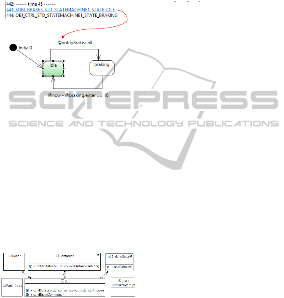
a CCAS’ State Diagram using MADES UML.
Figure 5: Graphical example using CCAS’ State Diagram.
In Figure 5, the user clicks on “state line” at
time 45 in formal results. After that, the traceability
technique — using our mapping — selects to him the
right UML element, in this case a state called Idle in a
State Diagram. The technique also changes the color
of this state to help the user to understand what is
happening. After this process, the user have a colored
state in a State Diagram which represent the “state
line” clicked before.
6 FROM TRACE TO UML
MODEL
This section presents a resume of how the traceability
technique is applied to CCAS example modeled using
MADES UML. The Figure 6 shows a Class Diagram
for the CCAS example.
Figure 6: Class Diagram for the CCAS example.
The CCAS model go through a transformation
into a LISP script using CorrettoUML tool and then
a verification by Zot model checker. Finally, the Zot
trace file — with the formal results — is opened in
the prototype plug-in for this traceability technique
together with the mapping and UML model. Figure 7
shows the CCAS example in Eclipse IDE with our
plug-in.
As can be seen in Figure 7, the user clicks
in line 926 at time 94 which contains an element
called OBJ BUS OP SENDBRAKECOMMAND. The
user does this action in Trace Checker View (1).
The action expands a node that contains an operation
sendBrakeCommand() and select it in hierarchical
treeview (2). Then, the equivalent Class Diagram (see
Figure 6) is displayed and the respective operation
(to the node) is also selected in the graphical
representation (3). Therefore, now the user have a
better understanding about line 926 in formal results.
The visualization of the formal results and its
manipulation through the act of clicking on the
desired line is our way to guarantee that the mapping
is correct. All this process could be transparent to
user if required. To the user is important to see where
the data is passing through the UML model, similar
to what happens in the debug process. The current
state is just a way to ensure that mapping is doing its
working correctly.
Preliminary tests shows that this traceability
technique can be used also with others UML
diagrams (e.g. Component Diagram) and SysML,
since their elements have ID like UML elements
in MADES UML — at least when modeling in
Papyrus. In addition, future works include the
creation of mapping methods for other transformation
tools besides CorrettoUML. Finally, Zot trace is a
textual file so in theory a formal result in textual
format can be analyzed by the traceability technique
and its mapping methods.
Another functionality for this mapping is a type
of “model search”. Here, the technique can find
other occurrences of the UML element in analysis and
show them to the user. For example, the user can
see that a message in Sequence Diagram has a link
to a particular operation in Class Diagram. For this
to happen, first the model should allow this type of
association. Then, the technique checks for any ID (in
mapping) associated with the current UML element
which user is looking. If there is then a “model
search” view shows all occurrences and allows the
user to navigate between them.
7 LESSONS LEARNED
During this study, several observations were noticed.
Although Papyrus Modeling Editor is a robust
graphical editing tool for UML in Eclipse IDE and
provides a well-documented API, it is still under
strong development. As result, some implementations
ICEIS2015-17thInternationalConferenceonEnterpriseInformationSystems
326
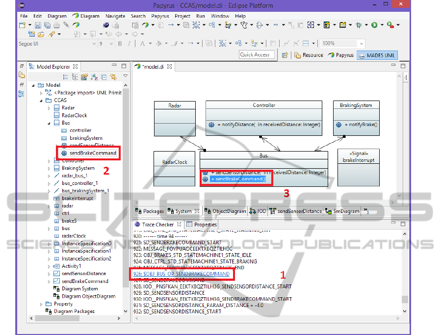
Figure 7: Traceability Example.
regarding transformation in UML elements may need
to be updated in a near future. A new version of
Papyrus — available during this study — helps to
minimize this issue, but the problem still exists.
Another issue related with Papyrus is that the
process to control UML elements in both graphical
representation and hierarchical treeview is not trivial
and it was necessary the collaboration of Papyrus’
development team when they were available. In fact,
this is a limitation of MADES UML, because it only
works with Papyrus. The only way to model a system
with MADES UML is through Papyrus, so anyone
that wishes to work with MADES UML need to learn
how to work with Papyrus and its possible issues.
One more limitation of MADES UML could be
the fact that to properly model a system, one should
learn about TRIO and its temporal logic operators,
which it is not trivial. This knowledge is necessary if
one wants to write properties and check if the model
holds them or not. MADES UML provides a more
simple approach to write these properties, by using a
Time Property Diagram, but even with this diagram,
it is still required to know temporal logic.
In terms of design, we have sought the simplicity.
For example, the mapping file created in this study is
intuitive to manage by people that may maintain the
tool. Even if MADES UML were updated, such as
adding a new diagram or the use of another model
checker, make changes in our technique tends to not
be complicated due to this simplicity.
The traceability technique works direct with
diagrams present in UML model and the trace with
formal results. Due to this, if UML model has a many
diagrams or the diagrams have too much elements,
or even the trace is a big file, then it will take more
time to represent everything in the UML model for
the user. Nevertheless, it will be less time consuming
than the manual analyzes performed so far by the user.
Therefore, scalability is a point of interest that should
be examined in future work.
MappingFormalResultsBacktoUMLSemi-formalModel
327

8 CONCLUSION AND FUTURE
WORKS
This paper presented a traceability technique for
MADES UML and its support tools. The technique
focused on map the formal results produced by
MADES UML tools to the “original” UML model.
The paper described how the technique was defined,
the requirements to use it, how to create and apply
the mapping, as well as an example of how graphical
representations may help the users to understand the
information of the formal results.
The traceability technique presented here aims
to assist MADES UML and its formal semantics
filling the gap in how to trace back formal results
to UML model. We achieve this by guiding the
user through the analysis of formal results present
by MADES UML formal verification tool. This
enhances the users’ understanding level about the
results and thereby he/she can find possible defects
more easily, fixing them and improving the UML
model.
In spite of, the traceability technique has been
presented together with MADES UML, theoretically
our technique may be expanded to work with
other UML diagrams and different model checkers.
In addition, it could work with other studies on
formalization of the UML semantics.
Regarding the technique improvements, the
following topics are currently under development
or analysis: ((i)) Improvements in traceability
technique and its plug-in; (ii) Development of the
Graphical Transformation Builder to display the
data from formal results to user through graphical
representations in the UML model; (iii) Application
of the technique on case studies; (iv) Analysis
of the possibility of using other tools besides
CorrettoUML and Zot; and (v) Feasibility of
extending the technique and use it outside MADES
UML environment.
We believe that with this technique, the user
can obtain information concerning the formal results
without having high knowledge about temporal logic,
LISP, model checking, etc. The whole process exists,
but the complexity can be decreased or even omitted
from users, making “transparent” (if possible) any
formal aspect.
ACKNOWLEDGEMENTS
The Brazilian funding agencies CAPES (Grant. No.:
DS-7902801/D) and CNPq, through Science without
Borders program (Grant. No.: 245715/2012-6),
support this research.
REFERENCES
Bagnato, A., Sadovykh, A., Paige, R., Kolovos, D.,
Baresi, L., Morzenti, A., and Rossi, M. (2010).
MADES: Embedded systems engineering approach in
the avionics domain. In HoPES’10.
Baresi, L., Morzenti, A., Motta, A., and Rossi, M. (2012).
Towards the UML-based formal verification of timed
systems. In FMCO’12, volume 6957 of LNCS, pages
267–286. Springer Berlin/Heidelberg.
Borger, E., Cavarra, A., and Riccobene, E. (2000). An ASM
semantics for UML activity diagrams. In AMAST’00,
pages 293–308. Springer-Verlag.
Bouabana-Tebiel, T. (2009). Semantics of the interaction
overview diagram. In IRI’09, pages 278–283,
Piscataway, NJ, EUA. IEEE Press.
Broy, M., Crane, M. L., Dingel, J., Hartman, A.,
Rumpe, B., and Selic, B. (2006). 2nd UML 2
semantics symposium: formal semantics for UML. In
MoDELS’06, pages 318–323. Springer-Verlag.
Cengarle, M. V. and Knapp, A. (2005). Operational
semantics of UML 2.0 interactions. Technical Report
TUM-I0505, Technische Universitt Mnchen.
Ciapessoni, E., Coen-Porisini, A., Crivelli, E., Mandrioli,
D., Mirandola, P., and Morzenti, A. (1999). From
formal models to formally-based methods: an
industrial experience. ACM TOSEM, 8(1):79–113.
Diethers, K. and Huhn, M. (2004). Vooduu: Verification
of object-oriented designs using UPPAAL. In
TACAS’04, volume 2988 of LNCS, pages 139–143.
Eriksson, H. E., Penker, M., and Lyons, B. (2004). UML 2
Toolkit, volume 1 of OMG Series. Wiley Pub.
Eshuis, R. (2006). Symbolic model checking of UML
activity diagrams. ACM TOSEM, 15:1–38.
Goldsby, H., Cheng, B. H. C., Konrad, S., and Kamdoum,
S. (2006). A visualization framework for the modeling
and formal analysis of high assurance systems. In
MoDELS’06, volume 4199 of LNCS, pages 707–721.
Grobelna, I., Grobelny, M., and Adamski, M. (2010).
Petri nets and activity diagrams in logic controller
specification - transformation and verification. In
MIXDES’10, pages 607–612.
Hammal, Y. (2005). A formal semantics of UML statecharts
by means of timed petri nets. In FORTE’05, pages
38–52, Berlin, Heidelberg. Springer-Verlag.
Hutchinson, J., Whittle, J., Rouncefield, M., and
Kristoffersen, S. (2011). Empirical assessment of
MDE in industry. In ICSE’11, pages 471–480.
Kaliappan, P. and Konig, H. (2012). On the formalization of
UML activities for component-based protocol design
specifications. In SOFSEM’12, volume 7147 of
LNCS, pages 479–491. Springer Berlin-Heidelberg.
Lund, M. S. and Stolen, K. (2006). A fully
general operational semantics for UML 2.0 sequence
ICEIS2015-17thInternationalConferenceonEnterpriseInformationSystems
328

diagrams with potencial and mandatory choice. In
FM’06, volume 4085 of LNCS, pages 380–395.
Mayerhofer, T., Langer, P., and Kappel, G. (2012). A
runtime model for fUML. In MRT’12, pages 53–58.
Micskei, Z. and Waeselynck, H. (2011). The many
meanings of UML 2 sequence diagrams: a survey.
Software and Systems Modeling, 10:489–514.
Motta, A. (2012a). Logic-Based Verification of
Multi-Diagram UML Models for Timed Systems.
PhD thesis, Politecnico di Milano - Dipartimento di
Elettronica e Informazione.
Motta, A. (2012b). Towards the verification of
multi-diagram UML models. In ICSE’12, pages
1531–1534. IEEE Press.
Paltor, I. P. and Lilius, J. (1999). Formalising UML state
machines for model checking. In UML’99, pages
430–445, Berlin, Heidelberg. Springer-Verlag.
Pradella, M., Morzenti, A., and Pietro, P. S. (2007). The
symmestry of the past and of the future: bi-infinite
time in the verification of temporal properties. In
ESEC-FSE’07, pages 312–320. ACM.
Remenska, D., Templon, J., Willemse, T. A. C., Homburg,
P., Verstoep, K., Casajus, A., and Bal, H. (2013). From
UML to process algebra and back: An automated
approach to model-checking software design artifacts
of concurrent systems. In NFM’15, volume 7871 of
LNCS, pages 244–260. Springer Berlin Heidelberg.
Rossi, C., Enciso, M., and de Guzman, I. P. (2004).
Formalization of UML state machines using temporal
logic. Software and Systems Modeling, 3(1):31–54.
Saldhana, J. A. and Shatz, S. M. (2000). UML diagrams
to object petri net models: An approach for modeling
and analysis. In SEKE’00, pages 103–110.
Snook, C. and Butler, M. (2006). UML-B: Formal modeling
and desing aided by UML. ACM TOSEM, 15:92–122.
Storrle, H. (2003). Semantics of interactions in UML 2.0.
In HCC’03, pages 129–136. IEEE Computer Society.
MappingFormalResultsBacktoUMLSemi-formalModel
329
