
Cost-effective Functional Testing of Reactive Software
R. Venkatesh, Ulka Shrotri, Amey Zare and Supriya Agrawal
Tata Research Development and Design Centre, Pune, India
Keywords:
Formal Specification, Functional Test Generation.
Abstract:
Creating test cases to cover all functional requirements of real-world systems is hard, even for domain experts.
Any method to generate functional test cases must have three attributes: (a) an easy-to-use formal notation
to specify requirements, from a practitioner’s point of view, (b) a scalable test-generation algorithm, and (c)
coverage criteria that map to requirements.
In this paper we present a method that has all these attributes. First, it includes Expressive Decision Table
(EDT), a requirement specification notation designed to reduce translation efforts. Second, it implements
a novel scalable row-guided random algorithm with fuzzing (RGRaF)(pronounced R-graph) to generate test
cases. Finally, it implements two new coverage criteria targeted at requirements and requirement interactions.
To evaluate our method, we conducted experiments on three real-world applications. In these experiments,
RGRaF achieved better coverage than pure random test case generation. When compared with manual ap-
proach, our test cases subsumed all manual test cases and achieved up to 60% effort savings. More impor-
tantly, our test cases, when run on code, uncovered a bug in a post-production sub-system and captured three
missing requirements in another.
1 INTRODUCTION
Safety critical standards such as DO-178B (do1,
1994) mandate requirements coverage during func-
tional testing. However, functional test case gener-
ation is an intellectually demanding and critical task
that has a strong impact on the effectiveness and ef-
ficiency of the entire testing process (Anand et al.,
2013). For large and complex reactive software, it is
difficult even for domain experts to envision all inter-
actions between requirements. This sometimes makes
it impossible to write functional test cases that cover
all requirements and the interactions among them.
Hence, there is a need to automatically generate func-
tional test cases.
Random Test case Generation (RTG) (Arcuri
et al., 2010) and Model-Based Testing (MBT) (Dalal
et al., 1999) are two traditional techniques that are
used for functional test case generation for reactive
software. However, RTG generates input sequences
using only input signals and their types and does not
need specification of requirements of a system and
hence does not generate expected output along with
the generated input sequence. Additional efforts are
therefore required to determine the expected results.
Moreover, RTG is likely to generate a large number
of redundant test cases. MBT is implemented by sev-
eral tools (Reactis, ; Peranandam et al., 2012; Wang
et al., 2014; Harel et al., 1990), but it is not widely
adopted by the practitioners as the requirements need
to be specified in a formal language supported by the
tool. Often, the language supported by these tools
demands a strong mathematical background from the
user or require the user to design the state space of
the problem even if it is not part of the requirements
(Thyssen and Hummel, 2013). This activity is effort-
intensive and adversely affects the overall cost of the
approach. In fact, very little is known about the cost-
effectiveness of MBT (Briand, 2010). Moreover, the
syntactic structure of these languages is very different
from the original requirements description, so there
is no direct mapping from specifications to require-
ments. As a result, the coverage targeted by these
tools, such as state and transition coverage, does not
directly map to the requirements (Tahat et al., 2001).
MBT tools use a combination of random generation
and constraint solving to generate test cases, however,
neither of these techniques scale up to industry-size
applications (Cadar and Sen, 2013; P˘as˘areanu and
Rungta, 2010).
In short existing methods have the following limi-
tations - a) They are effort intensive as they either re-
quire a specification in a formal language or they need
expected results to be determined, b) The algorithms
67
Venkatesh R., Shrotri U., Zare A. and Agrawal S..
Cost-effective Functional Testing of Reactive Software.
DOI: 10.5220/0005347800670077
In Proceedings of the 10th International Conference on Evaluation of Novel Approaches to Software Engineering (ENASE-2015), pages 67-77
ISBN: 978-989-758-100-7
Copyright
c
2015 SCITEPRESS (Science and Technology Publications, Lda.)

they implement do not scale up to industry-size ap-
plications and c) The generated test cases do not map
directly to requirements.
We present a requirements-driven method, EDT-
Based Testing (EBT), that overcomes the aforemen-
tioned limitations with current MBT methods. To re-
duce specification efforts EBT uses Expressive De-
cision Tables (EDT) (Venkatesh et al., 2014) as a
formal language. The authors of (Venkatesh et al.,
2014) have shown that EDT is more efficient and ef-
fective for specifying functional requirements of re-
active systems, as compared to a state-based formal-
ism such as Statecharts (Harel et al., 1990) and Soft-
ware Cost Reduction (SCR) (Heitmeyer et al., 1998).
In an EDT specification, rows map directly to re-
quirements that are described in a natural language.
EBT includes a novel algorithm that combines row-
guided random input generation with fuzzing at time
boundaries (RGRaF) to scale up test case genera-
tion. We have implemented the RGRaF algorithm in
a tool called EDT-Test. We introduce row and row-
interaction coverage criteria that target: 1) the row
coverage to measure the coverage of requirements
and, 2) the row-interactions coverage to measure the
interaction between the requirements. We also man-
ifest a novel use of EDT to allow users to model
the environment and specify properties/invariants of
the system for detecting errors, leading to better test
cases. To summarize, EBT involves a) Specifying
requirements in EDT b) Modelling environment and
system properties in EDT c) Generating test cases that
cover rows and row-interactions using RGRaF.
To evaluate the cost-effectiveness and scalability
of EBT, we conducted case studies where we spec-
ified requirements of ten software modules of three
automotive projects in EDT. We then generated test
cases using EDT-Test and evaluated the scalability of
our algorithm by: a) comparing it with a pure random
test case generation algorithm and, b) comparing it
with RGRaF without fuzzing. As manually created
test cases and effort data of all the case studies were
available to us, we assessed the cost-effectiveness of
EBT. Our findings clearly show that RGRaF scales
better than both pure random test case generation and
RGRaF without fuzzing. It also showed that EBT is
more cost-effectivethan manual testing. Additionally,
during the case studies we found a bug in a production
code and uncovered gaps in requirements showing the
usefulness of the generated test cases.
We have compared our algorithm against a pure
random algorithm because constraint solving does not
scale up (P˘as˘areanu and Rungta, 2010). We validated
this through a small experiment in which we took
an example smaller than the ones in our case-study,
translated it to the C language and ran Autogen (Bokil
et al., 2009) on it. It was not able to generate any test
cases whereas EDT-Test covered all rows. Due to this
experience and findings from the experiment, we did
not compare EDT-Test against any constraint solving
based tool.
The main contribution of this paper is a cost-
effective method, EBT, to generate functional test
cases. This is achieved by the following:
• Using EDT as a specification language to reduce
the effort required in specifying requirements and
extending EDT with constructs that enable easy
modelling of the environment.
• A new row-guided random algorithm that also
adds fuzzing at time boundaries to scale up test
generation.
• Targeting two new test coverage criteria, row and
row-interaction coverage, which ensure that all
requirements and interactions between require-
ments are tested adequately.
The organization of the paper is as follows. Sec-
tion 2 discusses the related work. We explain the EDT
Notation in brief in Section 3. Two new coverage cri-
teria, row and row-interaction, are introduced in Sec-
tion 4. Section 5 describes our algorithm, RGRaF, in
detail. We present extensions to EDT in Section 6
and describe the observations and findings of the ex-
periments conducted in Section 7. Finally, Section 8
concludes the paper.
2 RELATED WORK
In this section, we discuss a few of the several relevant
publications related to automated test case generation.
These are grouped based on the source specification
language, the technique employed and the coverage
criteria targeted.
Generating test cases from specifications has re-
ceived a lot of attention with tools that have a va-
riety of input languages. There are tools based on
languages such as Software Cost Reduction method
(SCR) (Heitmeyer et al., 1998), Statecharts (Offutt
et al., 2003), Z (Cristi´a et al., 2014), Spec# (Veanes
et al., 2008), and Lustre (Raymond et al., 1998).
These languages require test engineers to specify the
requirements of the system under test (SUT) in the
form of mathematical expressions or state diagrams,
which takes a lot of effort. Tahat et al. (Tahat et al.,
2001) have proposed an approach to generate test
cases from requirements given in textual and SDL
format, but they too do not have any data to show
the benefits of their approach nor have they evaluated
ENASE2015-10thInternationalConferenceonEvaluationofNovelSoftwareApproachestoSoftwareEngineering
68

Table 1: EDT for Alarm feature.
sno
in
Ignition
in
Alarm
in PanicSw out Alarm out Flash
1 Off Off {{Press;Release}{=2}}{<3s} On{=30s};Off {On{=500ms};Off{=500ms}}{=30};No Req
2 On Press{>3s};Release Off No Req
3 On Off No Req
their approach for cost-effectiveness. To the best of
our knowledge, there has been no work that compares
the effort required to specify requirements in a formal
language and generate test cases using a tool for in-
dustry examples. EBT reduces the effort required for
specification by choosing a compact and easy to use
notation, EDT (Venkatesh et al., 2014).
Additionally, all the aforementioned tools target
a coverage criterion that is natural to the formal lan-
guage being used. Thus, if the language is Statecharts
based then the state and transition coverage criteria
are targeted, and in the case of Z, pre-/post-operation
relations are considered as coverage criteria. As a re-
sult, these coverage criteria do not always achieve re-
quirements coverage. In contrast, EDT-Test generates
test cases to achieve row and row-interaction cover-
age giving direct mapping to requirements coverage
as EDT rows map directly to requirements.
Several tools employ a constraint solver or a
model-checker to generate test cases. These include
Java Path Finder (Brat et al., 2000), Autogen (Bokil
et al., 2009), KLEE (Cadar et al., 2008) and Pex (Till-
mann and De Halleux, 2008). The scalability of
constraint solvers (Cadar and Sen, 2013; P˘as˘areanu
and Rungta, 2010) continues to limit the applicabil-
ity of these techniques and there are still some chal-
lenges that need to be overcome for its wider adop-
tion (Cadar et al., 2011). Random testing (Hamlet,
2002) has also been studied extensively as an alterna-
tive to systematic testing as it is very easy to gener-
ate a large number of test cases randomly. Theoret-
ical studies indicate that random testing is as effec-
tive as systematic testing (Duran and Ntafos, 1984;
Chen et al., 2010). On the other hand, empirical stud-
ies (Ferguson and Korel, 1996; Marinov et al., 2003)
have shown that pure random testing achieves less
code coverage than systematic test generation. Un-
like existing methods, EBT implements a row-guided
random technique with fuzzing at time boundaries to
achieve scalability and coverage.
3 EDT NOTATION
EDT (Venkatesh et al., 2014) is a tabular notation
to formally specify requirements of reactive systems.
This notation is designed in a manner that makes it
easy to understand and use, and yet keeps it formal
enough to enable automated test case generation. It
provides a uniform notation to specify both – state-
based and sequence-based requirements, leading to
compact specifications of reactive systems.
An EDT specification consists of one or more ta-
ble(s) where the column headers specify the input and
output signal names, and the rows specify relation-
ships between patterns of input and output signal val-
ues or events. We illustrate EDT through partial re-
quirements of the Alarm module of a real world auto-
motive application, which are described below:
1. If Ignition and Alarm are Off, and PanicSw is
pressed and released twice within 3 seconds, then
Alarm should be On for 30 seconds, and Flash
should blink 30 times with a gap of 500 millisec-
onds between each On and Off and should have
No
Req after that.
2. If Alarm is On and PanicSw is pressed for more
than 3 seconds and then released (called as long
press), then the Flash should be No
Req and
Alarm should be Off.
3. If Ignition becomes On, then Flash should be
No Req and Alarm should be Off.
Table 1 specifies the above requirements using EDT,
in which each row maps directly to one of the require-
ments. The column headers specify three input sig-
nals: Ignition, PanicSw and Alarm, and two output
signals: Flash and Alarm. Its is worth noting that
Alarm is an input and output (I/O) signal. The pattern
expressions in each input cell specify the sequence of
input value(s) that will match the requirements of that
cell. The pattern expressions in an output cell spec-
ify the sequence of signal value(s) that will be output
when the requirements of all the input cells in that row
are matched. The pattern language itself is regular, as
EDT supports a discrete timed model, and can be rec-
ognized by a discrete timed automaton (Bowman and
Gomez, 2006). The pattern Off given in the first row
for columns corresponding to the signals Ignition and
Alarm matches when the environment sends the value
Off to the system. The compactness of EDT is illus-
trated by the pattern ‘{{Press;Release}{=2}}{<3s}’
which is detected when the values Press followed by
Release are received twice within three seconds for
the signal PanicSw. The output pattern in the first
Cost-effectiveFunctionalTestingofReactiveSoftware
69
row corresponding to the signal Flash specifies that
the values On followed by Off should be output with
a gap of 500 milliseconds, and this pattern should be
repeated 30 times.
4 COVERAGE CRITERIA
To effectively test the system specified using EDT,
we propose two coverage criteria – row coverage and
row-interaction coverage, which are described below:
4.1 Requirement/Row Coverage
An EDT row is covered when it is matched in at least
one generated test case. Complete row coverage is
said to be achieved when all rows in the EDT are cov-
ered. The intuition behind row coverage is that an
individual requirement can often be mapped to one
or more EDT row(s) and hence row coverage implies
requirements coverage.
Table 2 illustrates a test case corresponding to
EDT specification shown in Table 1. The default val-
ues of input signals Ignition and Alarm are consid-
ered to be Off. When PanicSw values are generated
as Press followed by Release twice within three sec-
onds, that is at time 1500 milliseconds (ms) in Table
2, Row 1 is matched and hence the expected output of
Alarm is On and the flashing pattern is ‘On followed
by Off’.
4.2 Requirement-Interaction/
Row-Interaction Coverage
Requirements, as specified in EDT, can have the fol-
lowing two types of interactions between them:
• I/O row-interaction: (r
1
, r
2
) is said to be a I/O
row-interaction if r
1
outputs a value that is used
by r
2
.
• O/O row-interaction: (r
1
, r
2
) is said to be a O/O
row-interaction if both r
1
and r
2
output values for
the same signal at the same time.
Row-interaction is covered when a test case cap-
tures either of the aforementioned interactions be-
tween rows.
In the example mentioned in Table 1, because of
the common I/O signal Alarm, there are three I/O row-
interactions: (1, 2), (2, 1) and (3, 1). This is because
the output On to Alarm in Row 1 is used by Row 2
and the output Off to Alarm in Rows 2 and 3 is used
by Row 1. The input sequence shown in the test case
in Table 2 covers the row-interaction (1, 2).
Table 2: Test Case for Row and I/O row-interaction cover-
age.
Time(ms) Input Signals Remarks
0 PanicSw=Press
500 PanicSw=Release
1000 PanicSw=Press
1500 PanicSw=Release Row 1 output starts
2000 PanicSw=Press
5500 PanicSw=Release Row 2 output starts
Table 3: Test Case for O/O row-interaction coverage.
Time(ms) Input Signals Remarks
0 PanicSw=Press
500 PanicSw=Release
1000 PanicSw=Press
1500 PanicSw=Release Row 1 output starts
2000 Ignition=On Row 3 output starts
In Table 1, Rows 1 and 3 form an O/O row-
interaction (1, 3) as both these rows can potentially
affect the output value of the same signal Flash at the
same time. Consider the input sequence shown in Ta-
ble 3. At time 1500 ms, the output pattern for Flash
will start because Row 1 is matched. However,at time
2000 ms the output of Flash is changed to No
Req,
although the previous output pattern is still going on.
This happens because Row 3 is matched due to the
occurrence of Ignition = On. When such input se-
quence is generated in a test case, it is said to have
covered O/O row-interaction (1, 3).
5 RGRaF: ROW-GUIDED
RANDOM ALGORITHM WITH
FUZZING
We now present RGRaF (Figure 3), an algorithm to
generate test cases with expected output from EDT
specifications. A test case consists of a timed se-
quence of input values and corresponding expected
output values. Each element of the sequence is a
tuple of the form (signalname, value,time, category)
where, signalname is an input signal, value is a valid
value for that signal, time is the time when the value
arrives, and category indicates if the signal is an in-
put, output or I/O signal. The sequence is arranged
in increasing order of time. The test case generation
algorithm that generates a set of these sequences con-
sists of four main steps; Automata construction, In-
put sequence generation (
InpGen
), Expected output
sequence generation (
ExpGen
) and fuzzing at time-
boundaries (
Fuzz
).
RGRaF begins by building a discrete timed au-
tomaton corresponding to the regular expression in
ENASE2015-10thInternationalConferenceonEvaluationofNovelSoftwareApproachestoSoftwareEngineering
70

InpGen()
Create a random sequence of rows R
s
I
s
:= ∅
For each r in R
s
I
r
:= Expand(r)
I
s
:= I
s
. I
r
End For
return I
s
Figure 1: InpGen.
ExpGen(I
s
)
For each row r in table T
τ := ExecuteAutomata(r,first(I
s
)
If (r matches)
I
s
:= I
s
⊕ O
p
of r
M
r
:= M
r
∪ r
End If
For all rows r
i
that produce some input of r
M
i
:= M
i
∪ {hr
i
, ri}
End If
τ
min
:= min (τ
min
, τ)
End For
Return (M
r
, M
i
, τ
min
)
Figure 2: ExpGen.
each cell, using known techniques. It then invokes
InpGen
, which selects a random sequence of rowsand
then systematically expands each row in the sequence
to produce a sequence of inputs that may match that
row. This input sequence is passed on to
ExpGen
,
which executes the timed automaton of each cell for
each input to determine the rows that match. When
a row matches,
ExpGen
modifies the input sequence
by adding outputs generated by the matched row, thus
creating the final test sequence. During its execution,
ExpGen
invokes
Fuzz
which randomly fuzzes the time
of inputs to increase the probability of time related re-
quirements getting covered. This sequence of
InpGen
and
ExpGen
is repeated till either all rows and row-
interactions are covered or the number of row se-
quences tried exceeds a given threshold (sample size),
S. These steps are described in detail below:
5.1 InpGen: Input Sequence
Generation
This function, Figure 1, first creates a row-sequence
R
s
by randomly selecting some EDT rows, including
uncovered rows with a higher probability. It then in-
RGRaF Algorithm:
U
r
:= Set of all rows(R
t
)
U
p
:= Set of row-interactions(R
p
)
i := 0
For each cell in each row r
Build its timed automaton
End For
While (i ≤ S and (U
r
6= ∅ or U
p
6= ∅ ))
I
s
:= InpGen()
While (I
s
6= ∅)
(M
r
, M
i
, τ) := ExpGen(I
s
)
U
r
:= U
r
- M
r
U
p
:= U
p
- M
i
I
s
:= I
s
→ Next
Fuzz: Randomly change time of first(I
s
)
to before or after τ
End While
i := i+1
End While
Figure 3: RGRaF Algorithm.
vokes the function Expand, which generates an input
sequence for each cell of each row r in R
s
, by select-
ing an element from the language specified by that
cell’s regular expression. The sequences of all the
cells of a row are merged, maintaining time ordering,
to get an input sequence I
r
for the row. Each I
r
is
appended to I
s
to get an input sequence for the row.
Note that the expansion of each row proceeds inde-
pendent of the other rows in the sequence and does
not take into account any value for I/O variable that
may be generated by a previous row. As a result, the
actual rows matching the generated sequence of in-
puts could be different from the rows in R
s
. This sys-
tematic expansion of rows ensures the generation of
input patterns that need repetition. The probability of
such repeated pattern getting generated will be low if
input generation is purely random.
5.2 ExpGen: Expected Output
Sequence Generation
ExpGen, Figure 2, takes as input a sequence I
s
, con-
sisting of inputs yet to be processed. Each input in
I
s
is processed by taking a step of each row r, of the
EDT table T. A step of a row consists of taking a
transition in the automaton of each cell in that row.
Once a step is taken a row matches if all its automata
are in their final state, with at least one of them hav-
ing reached the final state due to the current signal.
When a row matches, tuples with category output or
I/O corresponding to the output O
p
of that row are
Cost-effectiveFunctionalTestingofReactiveSoftware
71
merged (⊕) with the input sequence I
s
maintaining its
time ordering and the matched row is added to the set
of matched rows M
r
. If the current row matched due
to outputs generated by a previously matched row r
i
,
then the pair hr
i
, ri is added to the matched interac-
tions M
i
. Any I/O signal produced by a matched row
is processed in the next step. If an automaton is in
a state that has an outgoing time-out transition it is
said to be in a time-out state. Of all the automata in
a time-out state
ExpGen
returns the smallest time τ
min
at which a time-out transition may occur.
5.3 Fuzz: Fuzzing at Time Boundaries
As in standard discrete timed automata each transi-
tion of a cell’s automaton is either labelled by a signal
value or is a time-out transition of the form hc, op, ni
where c is a clock variable, op is one of the oper-
ators {<, ≤, >, ≥} and n is a positive integer repre-
senting time. Time constraints modelled as time-out
transitions are one of the reasons why model-based
approaches to test generation do not scale up to in-
dustry size code. Random algorithms too are unable
to cover time-based requirements. To address this is-
sue, at the end of each step, we randomly change the
time of inputs occurring around the nearest time τ, at
which a time-out may occur. The generated scenario
is altered by randomly changing the time of some in-
puts that occur either - a) before τ to a time after it or
b) after τ to a time before it.
We call the above alteration fuzzing at time bound-
aries. Consider the scenario presented in Table 2. Af-
ter processing the input at 1500ms, the nearest time-
out will occur at 3000ms due to the PanicSw pattern in
Row 1 of the example given in Table 1. At this point,
the algorithm could randomly choose to fuzz the sce-
nario by changing the time of the input at 2000ms to
3500ms or it could change the time of the input oc-
curring at 5500ms to 2500ms. If fuzzing is not per-
formed, the scenario will be generated only at the
3000ms that is the time-out. Hence, fuzzing helps in
generating scenarios with different time around τ and
thus helps in covering complex time-based scenarios.
All these steps are repeated until full row coverage
and row-interaction coverage is achieved (i.e., U
r
=
∅ ∧ U
p
= ∅), or the number of row sequences tried
exceeds the sample size S.
6 EXTENSIONS TO EDT
For the generated test cases to be useful it should
not have any input combinations that will never be
generated by the environment. To eliminate such in-
valid combinations the environment needs to be spec-
ified. We have extended the EDT notation with a
special output column
RejectFlag
to support easy
modelling of the environment as required for test-
ing. Similarly, we have also added a special col-
umn
ErrorFlag
to support specification of proper-
ties. These two extensions are described in detail be-
low.
6.1 Modelling Environment Constraints
In reactive systems, there could be several combina-
tion(s) of input(s) that can never occur in the actual
run of the system. For instance, in a car, the left
and right indicator switches cannot be On simultane-
ously. We provide a special output signal, RejectFlag
to model such environment constraints. These con-
straints are specified as an EDT row with a Reject out-
put to the RejectFlag column. Sample EDT row spec-
ifying an environmentconstraint is illustrated in Table
4. If a test case generated by the Input Sequence Gen-
Table 4: Specification for Environment Constraints.
sno in LeftSw in RightSw out RejectFlag
1 On On Reject
erator matches the row in Table 4, then that test case is
rejected. So RejectFlag is actually used to eliminate
test cases for all the combinations that cannot happen
in the functioning of real-world reactive systems.
6.2 Property Checking
The requirements of real-world reactive systems gen-
erally contain certain safety-critical requirements that
should never be violated during any execution of the
system. These can be seen as properties of the sys-
tem. For example, ‘when a vehicle is moving at a
considerable speed (say, >20 kmph), all doors should
be locked’, is one such requirement. It is often eas-
ier to express such requirements as a system prop-
erty. This property should not be violated by other re-
quirements that alter either the vehicle speed or door
lock/unlock status. To specify such properties, we
provide a special output signal, ErrorFlag. An ex-
Table 5: Specification for Property Checking.
sno
in
VehicleSpeed
in DoorStatus out ErrorFlag
1 > 20 Unlocked Error
ample of specifying system properties is illustrated in
Table 5. As RGRaF generates test cases for row cov-
erage, to cover the row in Table 5, a test case will
be generated that matches this row. Once the row
ENASE2015-10thInternationalConferenceonEvaluationofNovelSoftwareApproachestoSoftwareEngineering
72

is matched, Expected Output Generator will generate
‘Error’ as the expected output of that test case. This
test case is a counter-example to the given property.
So this special output signal is actually used to detect
and report error for all the signal combinations that
are possible in real-world reactive systems but should
not occur due to pre-defined system properties.
7 EXPERIMENTS: RESULTS AND
OBSERVATIONS
To evaluate the cost-effectiveness and practical use-
fulness of EBT, we conducted case studies on differ-
ent projects. The case studies were conducted to an-
swer the following four questions:
1. Does RGRaF perform better than RGRaF without
fuzzing on real-world projects?
2. Does it take lesser effort to generate test cases
manually when compared with the effort required
to translate requirements to EDT and then gener-
ate test cases?
3. Does RGRaF generate better test cases than the
manually written test cases?
To investigate the aforementioned questions we
needed real-world projects which had documented re-
quirements in a natural language, manually written
test cases and also detailed data of effort spent in writ-
ing these test cases. We could find only a few such
projects, of which we selected three from the auto-
motivedomain. We carved out three case studies from
these projects such that each case-study was fairly big
and was representative of a real-world reactive sys-
tem.
Brief description of the three case studies followed
by details of the comparisons are given below.
Case Study 1 was from Body Control component
of an automotive original equipment manufacturer
(OEM). It consisted of a single sub-system named
Integrated-FAT that had three modules – Flasher,
Alarm and Trunk Back Door. Each module was fur-
ther divided into sub-modules and requirements of
sub-module were available. We modelled these re-
quirements in EDT and generated test cases for each
module as well for the sub-system level.
Case Study 2 was from another automotive OEM.
We conducted experiments on four modules – Power
Lift Gate (PLG), Power Closure Decision (PCD) and
Panic Alarm from Body Control component, and also
for Blower Control module from Climate Control
component. For all these modules and a sub-system
(Integrated-PLG+PCD) that merged PLG and PCD,
we generated test cases in MATLAB compatible for-
mat.
Case Study 3 was from Engine Control component
of an automotive tier one supplier. We generated test
cases, in CoverageMaster winAMS (winAMS, ) com-
patible format for three modules – TF Switch Open,
TF Switch Low and RD Switch Operation.
7.1 Comparison of RGRaF and Pure
Random with Fuzzing
To compare RGRaF with pure random test case gen-
eration we executed EDT-Test for both RGRaF and
pure random test case generation on all the modules
and sub-systems of the selected case studies. The
pure random algorithm generated random input se-
quences with a random time assigned to each tuple
in the input sequence. Each input sequence was of a
random length. Once an input sequence was gener-
ated, the rest of the algorithm was similar to RGRaF
and involved execution of automata and retained only
those sequences that covered a new row or a row-
interaction. In both cases a
Sample Size
S of 25000
was used.
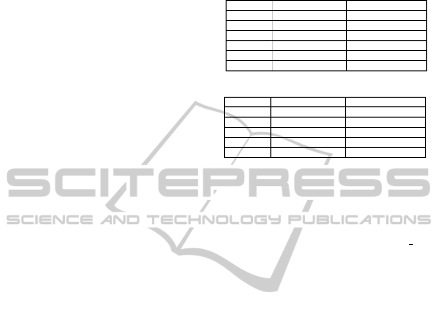
Table 6 illustrates the results of these experi-
ments. RGRaF achieved higher row coverage for
seven modules and higher row-interaction coverage
for eight modules as compared to pure random algo-
rithm. Moreover, RGRaF gave 100% row coverage
for seven modules whereas the pure random variant
could not cover all of them. During these experi-
ments, we observed that pure random test generation
was achieving lesser row and row-interaction cov-
erage for larger sub-systems/modules/systems. For
instance, in Alarm module, which had 822 rows,
RGRaF covered672 rows whereas pure random could
cover only 471 rows.
An analysis revealed that RGRaF performed bet-
ter in cases where size of input domain was large and
in cases where to cover a row an input with a specific
value had to be generated within a specific time. This
is illustrated by the example in Table 1. To cover Row
1 of this example the Panic Switch has to be pressed
and released twice within three seconds. The proba-
bility of this happening when the generation is purely
random is very low. When we generated test cases for
this example using RGRaF and pure random, RGRaF
needed a sample size of only 6 to cover all rows
and row-interactions, whereas the random algorithm
needed a sample size of 663. We also observed that
pure random with fuzzing algorithm generated many
invalid input combinations and hence were rejected.
Cost-effectiveFunctionalTestingofReactiveSoftware
73

Table 6: RGRaF and Pure Random.
Case Feature Name No. of No. of Rows Covered No. of Row-Interactions Covered
Study EDT RGRaF Pure RGRaF RGRaF Pure RGRaF
Rows Random Without Random Without
With Fuzz Fuzz With Fuzz Fuzz
Case Alarm 822 672 368 399 921 303 679
Study 1 Trunk Back Door 86 86 86 86 63 63 63
Flasher 146 125 121 120 541 506 503
Integrated-FAT 1052 683 580 579 1339 1176 1176
Case Panic Alarm 262 262 257 261 772 597 735
Study 2 Blower Control 101 101 101 101 280 279 271
PLG 52 51 51 51 301 301 301
PCD 16 16 16 16 5 5 5
PLG + PCD 68 67 65 64 296 290 285
Case TF Switch Open 14 14 14 14 22 22 22
Study 3 TF Switch Low 14 14 14 14 23 23 23
RD Sw Operation 31 31 26 23 46 35 31
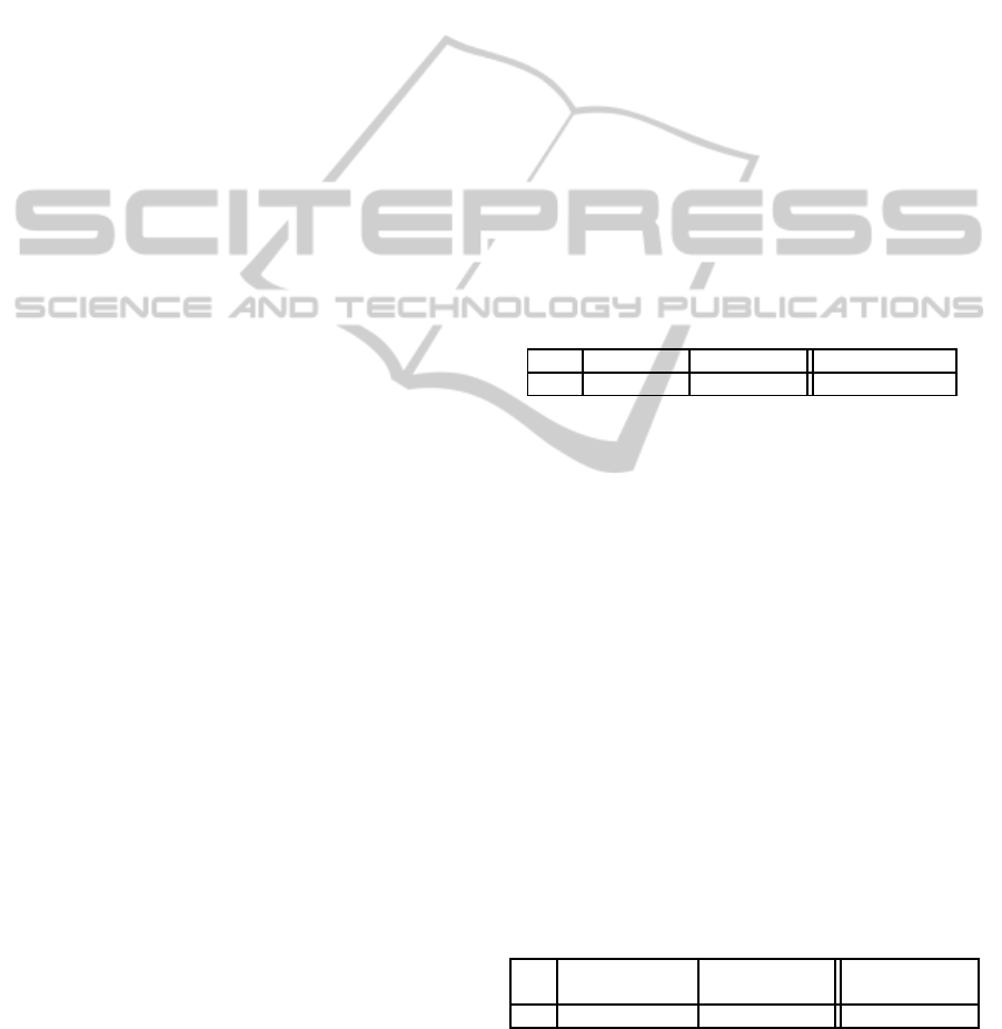
Table 7: Summary of EBT Experimental Data.
Case Feature Name
No.
of
Test Case Generation Using EBT Manual Test
Efforts
Study
EDT
EDT Creation EDT-Test Total Efforts Case Generation
savings
Rows
[person hours] Execution [person hours] [person hours]
by EBT
Case Alarm
822
13 95 mins 14.5 38.5
33%
Study 1 Trunk Back Door
86
7 2 mins 7 10
Flasher
146
18.5 32 mins 19 12
Integrated-FAT
1052
0 6.5 hours 6.5 Not Available
–
Case Panic Alarm
262
40 5 mins 40 80
44.8%
Study 2 Blower Control
101
5 12 mins 5 18
PLG
52
12.5 1.5 mins 12.5 6
PCD
16
1 1 second 1 2
PLG + PCD
68
0 30 mins 0.5 Not Available
–
Case TF Switch Open
14
0.75 1 min 0.75 9
62.5%
Study 3 TF Switch Low
14
1.25 1.75 mins 1.25 9
RD Sw Operation
31
10 1.5 mins 10 14
7.2 Comparison of RGRaF with
Fuzzing and RGRaF without
Fuzzing
To evaluate the contribution of fuzzing we ran EDT-
Test with and without fuzzing on all the modules. To
Fuzz, at the end of each step of all automata, the next
input was optionally chosen. If the chosen input had a
time less than the nearest time-out τ, then the time of
the input was modified to a value higher than τ else it
was changed to a time less than τ. For this comparison
too we used a
Sample Size
of 25000.
Table 6 presents the results of the comparison.
Fuzzing at time boundaries helped in seven mod-
ules because these had complex time-based require-
ments. For these modules, RGRaF achieved higher
row and row-interaction coverage as compared to
RGRaF without Fuzzing. This demonstrates that
fuzzing of timings of inputs helps in increasing row
and row-interaction coverage, especially in the pres-
ence of time-based requirements. A thorough analy-
sis revealed that Fuzzing helped in cases where there
were time constraints associated with I/O signals, as
explained in Section 5, because these I/O signals’
time constraints were not taken into account while ex-
panding rows.
7.3 Comparison with Manual Testing
For all the case studies, manually created test cases
with the corresponding efforts data were available to
us. These test cases were created by respective ap-
plication development teams consisting of test engi-
neers and domain experts whereas, the team that cre-
ated EDT specifications and generated test cases us-
ing EDT-Test did not have automotive domain knowl-
edge.
Table 7 presents a summary of our findings of a
comparison between EBT and manual test case gen-
eration for effort required. In the case of EBT the
ENASE2015-10thInternationalConferenceonEvaluationofNovelSoftwareApproachestoSoftwareEngineering
74

effort is split into the person hours taken to specify
requirements in EDT and the time taken by EDT-Test
to generate test cases. We have not compared the two
methods for coverage because no coverage data was
available for the manual test cases. Instead we asked
the domain experts from the project teams to manu-
ally compare and analyse the two sets of test cases.
The findings reveal that on an average EBT re-
quired 30%–60% less effort for test case creation. In
all the modules, EBT not only generated all the test
cases present in the manual sets, but also generated
many additional interesting scenarios. These addi-
tional scenarios should have been part of the manual
test cases according to the domain experts. In two
modules, Flasher and PLG, EBT test cases needed
more effort compared manual ones primarily because,
these modules required an understanding of complex
domain functionality which the manual test case writ-
ers already had.
Analysis of some key findings is presented below:
• In Case study 1, for the Trunk Back Door mod-
ule, EBT generated cases covered 40 more row-
interactions and in the case of Flasher it covered
346 more row-interactionsthan the manually writ-
ten test cases.
• In Case Study 1, Integrated-FAT module clearly
showed scalability of our algorithm. It had ap-
proximately 1000 requirements and 98 signals.
Due to the complexity of the requirements, it was
hard for the testers to visualize all the require-
ments’ combinations. Hence, the manually cre-
ated test cases covered only module level require-
ments and interactions between modules were not
adequately covered. EBT test cases subsumed all
the manually created ones and generated many
more valid and necessary requirements combina-
tions as confirmed by the domain experts and the
project team.
• In Case Study 2 EBT test cases, when run on the
model, detected a bug in a post-production sub-
system, Integrated-PLG + PCD. We detected this
bug by specifying properties of the sub-system us-
ing the ErrorFlag in EDT specifications, as ex-
plained in the Section 6. In case of Panic Alarm
module, three missing requirements were uncov-
ered when tool-generated test cases were executed
on MATLAB models.
• In Case Study 3, tool-generated test cases
achieved 100% statement and decision coverage
when executed on C code using CoverageMaster
winAMS. This is interesting because EBT does
not target code coverage.
The overall analysis of our experiments demon-
strates that, on real-world projects, RGRaF performs
better than pure random and than RGRaF without
fuzzing. It also shows that our EBT is more cost-
effective and generates better test cases than manual
test cases. However, there are some threats to validity
of our experiments and they are described in the next
section.
7.4 Threats to Validity
Below we list some threats to the validity of our find-
ings.
• All the systems we selected are from the auto-
motive domain and although the findings should
carry overto reactivesystems from other domains,
explicit experiments will have to be conducted to
confirm it.
• To judge the quality of the generated test cases
we relied on the judgement of domain experts.
A more scientific study that determines the num-
ber of defects detected by RGRaF will have to be
conducted to ascertain its effectiveness. However,
getting defect data is not easy and we were not
able to get it for all the systems we considered
making it a difficult experiment to conduct.
• Although we have considered fairly big systems,
modern reactive systems are much bigger. Con-
ducting an experiment on such a large application
will not be possible as it will take several person
months to specify these in EDT. We will therefore
have to see if RGRaF is actually used by testers to
get findings for large applications.
8 CONCLUSIONS AND FUTURE
WORK
In this paper, we have presented an effective and ef-
ficient automated technique for functional test case
generation. We have also shared the results of various
experiments that were conducted on three industry-
size applications, which highlight the advantages of
using the proposed technique on real-world reactive
systems. From the experiments we can conclude that:
• An appropriate choice of formal notation, com-
bined with automated test case generation, is ca-
pable of reducing testing efforts by around 30%-
60%, while providing better coverage.
• Row and row-interaction coverage criteria results
in several scenarios that are found useful and in-
teresting by test engineers and domain experts.
Cost-effectiveFunctionalTestingofReactiveSoftware
75

• Combining systematic generation of input se-
quences with a degree of randomness and finally
fuzzing at time boundaries performs better than
pure random test case generation.
Although the experiments were performed on au-
tomotive domain applications, we expect similar ben-
efits on reactive systems belonging to other domains
as well. The current version of the presented tech-
nique faces scalability issues in generating test cases
for applications having large and complex time-based
requirements, as observed in case study 1 with fea-
tures like Flasher and Alarm. Going forward, we aim
to overcome this issue by adding more intelligence
in the mechanism to generate input sequences. We
also targetto enhance the coverage criteria of the tech-
nique by evaluating the effectiveness of various cov-
erage criteria in finding bugs in the system under test,
and enable coverage of long sequences of require-
ments’ interaction.
REFERENCES
(1994). DO-178B: Software Considerations in Airborne
Systems and Equipment Certification.
Anand, S., Burke, E. K., Chen, T. Y., Clark, J., Cohen,
M. B., Grieskamp, W., Harman, M., Harrold, M. J.,
and Mcminn, P. (2013). An orchestrated survey of
methodologies for automated software test case gen-
eration. J. Syst. Softw., 86(8):1978–2001.
Arcuri, A., Iqbal, M., and Briand, L. (2010). Black-box sys-
tem testing of real-time embedded systems using ran-
dom and search-based testing. In Petrenko, A., Simo,
A., and Maldonado, J., editors, Testing Software and
Systems, volume 6435 of Lecture Notes in Computer
Science, pages 95–110. Springer Berlin Heidelberg.
Bokil, P., Darke, P., Shrotri, U., and Venkatesh, R. (2009).
Automatic test data generation for c programs. In
Secure Software Integration and Reliability Improve-
ment, 2009. SSIRI 2009. Third IEEE International
Conference on, pages 359–368. IEEE.
Bowman, H. and Gomez, R. (2006). Discrete timed au-
tomata. In Concurrency Theory, pages 377–395.
Springer London.
Brat, G., Havelund, K., Park, S., and Visser, W. (2000).
Java pathfinder - second generation of a java model
checker. In In Proceedings of the Workshop on Ad-
vances in Verification.
Briand, L. (2010). Software verification - a scalable, model-
driven, empirically grounded approach. In Tveito, A.,
Bruaset, A. M., and Lysne, O., editors, Simula Re-
search Laboratory, pages 415–442. Springer Berlin
Heidelberg.
Cadar, C., Dunbar, D., and Engler, D. R. (2008). Klee:
Unassisted and automatic generation of high-coverage
tests for complex systems programs. In OSDI, vol-
ume 8, pages 209–224.
Cadar, C., Godefroid, P., Khurshid, S., P˘as˘areanu, C. S.,
Sen, K., Tillmann, N., and Visser, W. (2011). Sym-
bolic execution for software testing in practice: Pre-
liminary assessment. In Proceedings of the 33rd Inter-
national Conference on Software Engineering, ICSE
’11, pages 1066–1071, New York, NY, USA. ACM.
Cadar, C. and Sen, K. (2013). Symbolic execution for soft-
ware testing: Three decades later. Commun. ACM,
56(2):82–90.
Chen, T. Y., Kuo, F.-C., Merkel, R. G., and Tse, T. (2010).
Adaptive random testing: The {ART} of test case di-
versity. Journal of Systems and Software, 83(1):60 –
66. SI: Top Scholars.
Cristi´a, M., Albertengo, P., Frydman, C., Pl¨uss, B., and
Monetti, P. R. (2014). Tool support for the test tem-
plate framework. Software Testing, Verification and
Reliability, 24(1):3–37.
Dalal, S. R., Jain, A., Karunanithi, N., Leaton, J., Lott,
C. M., Patton, G. C., and Horowitz, B. M. (1999).
Model-based testing in practice. In Proceedings of the
21st international conference on Software engineer-
ing, pages 285–294. ACM.
Duran, J. W. and Ntafos, S. C. (1984). An evaluation of
random testing. IEEE Trans. Softw. Eng., 10(4):438–
444.
Ferguson, R. and Korel, B. (1996). The chaining approach
for software test data generation. ACM Trans. Softw.
Eng. Methodol., 5(1):63–86.
Hamlet, R. (2002). Random Testing. John Wiley & Sons,
Inc.
Harel, D., Lachover, H., Naamad, A., Pnueli, A., Politi, M.,
Sherman, R., Shtull-Trauring, A., and Trakhtenbrot,
M. (1990). Statemate: A working environment for the
development of complex reactive systems. Software
Engineering, IEEE Transactions on, 16(4):403–414.
Heitmeyer, C., Kirby, J., Labaw, B., and Bharadwaj, R.
(1998). Scr: A toolset for specifying and analyzing
software requirements. In Computer Aided Verifica-
tion, pages 526–531. Springer.
Marinov, D., Andoni, A., Daniliuc, D., Khurshid, S., and
Rinard, M. (2003). An evaluation of exhaustive testing
for data structures. Technical report, MIT Computer
Science and Artificial Intelligence Laboratory Report
MIT -LCS-TR-921.
Offutt, J., Liu, S., Abdurazik, A., and Ammann, P.
(2003). Generating test data from state-based specifi-
cations. Software Testing, Verification and Reliability,
13(1):25–53.
Peranandam, P., Raviram, S., Satpathy, M., Yeolekar, A.,
Gadkari, A., and Ramesh, S. (2012). An inte-
grated test generation tool for enhanced coverage of
simulink/stateflow models. In Design, Automation
& Test in Europe Conference & Exhibition (DATE),
2012, pages 308–311. IEEE.
P˘as˘areanu, C. S. and Rungta, N. (2010). Symbolic
pathfinder: Symbolic execution of java bytecode. In
Proceedings of the IEEE/ACM International Confer-
ence on Automated Software Engineering, ASE ’10,
pages 179–180, New York, NY, USA. ACM.
ENASE2015-10thInternationalConferenceonEvaluationofNovelSoftwareApproachestoSoftwareEngineering
76

Raymond, P., Nicollin, X., Halbwachs, N., and Weber, D.
(1998). Automatic testing of reactive systems. In
Real-Time Systems Symposium, 1998. Proceedings.,
The 19th IEEE, pages 200–209. IEEE.
Reactis. Reactis. http://www.reactive-systems.com/model-
based-testing-simulink.html. [Online; accessed 3-
Dec-2014].
Tahat, L. H., Vaysburg, B., Korel, B., and Bader, A. J.
(2001). Requirement-based automated black-box test
generation. In Computer Software and Applications
Conference, 2001. COMPSAC 2001. 25th Annual In-
ternational, pages 489–495. IEEE.
Thyssen, J. and Hummel, B. (2013). Behavioral specifica-
tion of reactive systems using stream-based i/o tables.
Software & Systems Modeling, 12(2):265–283.
Tillmann, N. and De Halleux, J. (2008). Pex–white box test
generation for. net. In Tests and Proofs, pages 134–
153. Springer.
Veanes, M., Campbell, C., Grieskamp, W., Schulte, W.,
Tillmann, N., and Nachmanson, L. (2008). Model-
based testing of object-oriented reactive systems with
spec explorer. In Formal methods and testing, pages
39–76. Springer.
Venkatesh, R., Shrotri, U., Krishna, G. M., and Agrawal,
S. (2014). Edt: a specification notation for reactive
systems. In Proceedings of the conference on Design,
Automation & Test in Europe, page 215. European De-
sign and Automation Association.
Wang, J., Li, H., Lv, T., Wang, T., and Li, X. (2014). Func-
tional test generation guided by steady-state probabil-
ities of abstract design. In Proceedings of the confer-
ence on Design, Automation & Test in Europe, page
321. European Design and Automation Association.
winAMS, C. Coveragemaster winams.
http://www.gaio.com/product/dev
tools/pdt07 winams.html.
[Online; accessed 3-Dec-2014].
Cost-effectiveFunctionalTestingofReactiveSoftware
77
