
Efficient Ground Truth Generation based on Spatio-temporal Properties
for Lane Prediction Model
Jun Shiwaku and Hiroki Takahashi
Graduate School of Informatics & Engineering, the University of Electro-Communications,
1–5–1, Chofugaoka Chofu, Tokyo, 182–8585, Japan
Keywords:
Time Slice Image, Ground Truth, Spatio-temporal Image, Snakes.
Abstract:
Automobile safety has developed rapidly to prevent traffic accidents. Because of these techniques, traffic
accidents are decreasing year by year. There are however more than 4,000 fatal traffic accident cases per year in
Japan. Many lane detection systems are investigated. Those systems should be evaluated precisely and ground
truth is generally used for evaluations. Ground truth generation is however very hard and time-consuming
work. In this paper, an efficient ground truth generation method for reducing manual operations is proposed.
Firstly, time slice images are obtained from an in-vehicle video. Secondly, meanderings of the vehicle against a
lane are corrected by minimizing sum of squared differences of adjacent rows in the nearest time slice image.
Then, lane markers in all time slice images are extracted by propagating lane marker information from the
bottom time slice image to the upper one. Ground Truth is generated with contour information of the lane
markers offline. Offline ground truth generation methods are often used for constructing the lane prediction
model.
1 INTRODUCTION
The mobility industry is spreading around the world
in emerging countries as well as in developed coun-
tries. Traffic accidents are also in downward ten-
dency by developing automotive safety technologies
and tightening of traffic regulations. Traffic accidents,
however, occur as often as ever. Fatal traffic acci-
dents during rainfall become 1.67 times as many as
those during non-rainfall, because visibility worsens
at rainy days. Recently, headlights of cars are brighter
than ever with white and wide lights. It is easy to
recognize lane markers at night of fine weather be-
cause visibility is good. On the other hand, reflec-
tion occurs on lane markers at rainy night because on-
coming vehicles give off bright lights. Lane marker
denotes a center or outside line of a roadway, and
lane represents a road which vehicles are cruising be-
tween lane markers. A primary factor of the high
mortality in traffic accidents is the lane departure ac-
cidents. The lane departure accidents on the road
cause serious situation, against pedestrian, head-on
collision and fall accident. Lane keeping assist sys-
tem (TOYOTA MOTOR) prevents lane departure ac-
cidents. The system detects a lane and alerts a driver
with a buzzer, alert lamp and a small counter-steering
force when the vehicle faces to deviate from the lane.
The alert, however, does not work well sometimes,
when the lane cannot be detected. It is difficult to rec-
ognize lane markers by reflecting on oncoming ve-
hicle’s light in rainy days. Many researches have
adressed the problem (Meuter et al., 2009) (Linder
et al., 2009). In these research, ground truth is used to
evaluate the performance of those lane detection al-
gorithms. Ground truth means accurate data sets to
evaluate accuracy of an algorithm. Lane ground truth
is usually generated by setting points on lane markers
manually, one frame by one, and interpolating them.
It, however, takes an enormous amount of time and
feels mentally overloaded.
A lot of ground truth which become the lane infor-
mations is necessity of constructing the lane model.
This paper proposes an offline efficient ground truth
generation method based on shape changing features
of lane markers at time slice images for constructing
the lane prediction model.
2 RELATED WORKS
Many lane detection methods using a lane model
are proposed. Canny/Hough Estimation of Vanish-
455
Shiwaku J. and Takahashi H..
Efficient Ground Truth Generation based on Spatio-temporal Properties for Lane Prediction Model.
DOI: 10.5220/0005315004550460
In Proceedings of the 10th International Conference on Computer Vision Theory and Applications (VISAPP-2015), pages 455-460
ISBN: 978-989-758-090-1
Copyright
c
2015 SCITEPRESS (Science and Technology Publications, Lda.)

ing Points (CHEVP) (Wang and Teoh, 2004) is used
for B-snakes lane model. This algorithm is robust to
noises, shadows, and illumination variations in the
captured road images. Firstly, an image is divided
into multiple regions with horizontal lines. A lane
is detected by Hough transform and its contours are
extracted by Canny edge detector. Secondly, the cen-
ter line of the lane is calculated by using the extracted
contours and smoothed by B-spline. Finally, the lane
is extracted by using B-snakes with a lane model de-
rived from the center line.
A lane detection algorithm based on several lane
features for low visibility conditions is proposed by
Iwaki et al. (Iwaki and Takahashi, 2012). Images are
transformed into bird’s eye views in order to make a
lane marker into uniform width. Then the lane is ex-
tracted by tracking points that are arranged on lane
markers since the lane width is defined by the traffic
law. Furthermore, in order to improve accuracy in low
visibility conditions, this algorithm approximates the
extracted lane markers with a quadratic curve. Road
shapes are, however, varied, generally, roads have var-
ious shapes. In particular, highway roads are designed
by clothoid, which is also known as a cornu spiral.
The segments are used as transition spirals forming
c-shaped and s-shaped curves and continuous curva-
ture between circles as well as straight lines in various
situations (Sasipalli et al., 1997).
Lane detection systems are evaluated using
ground truth, and six representative road feature ex-
tractors are evaluated using two variants by Veit et al.
(Veit et al., 2008). An efficient method to generate
ground truth is proposed by Borkar et al. (Borkar
et al., 2010). Firstly, it generates time slice images
which are sliced parallel to time axis and horizontal
axis of spatio-temporal image. Secondly, a user man-
ually marks some points with any intervals on the cen-
ters of the lane markers on a few time slice images.
Then, those points are interpolated by spline interpo-
lation. Other points on lane markers in a frame are
obtained by this operation. Manual work, however,
still remains. Since a few control points are used as
the interpolation, accuracy is not sufficient secured.
Edge or contour detection algorithms have been
proposed. Snakes, or active contours, are contours
extraction method which is adaptive for shape vari-
ations (Michael et al., 1988). Oike et al. (Oike,
2001) proposes a road edge tracking method based
on a constraint that moves only in the horizontal di-
rection to the control points of the snakes. Sawano et
al. (Sawano and Okada, 2007) proposes a lane marker
tracking method by using snakes. A lane marker has
two edges of inner and outer a lane. In a road scene,
if the road has lane markers on both sides, it is totally
four edges. Parameters of snakes can be respectively
given for their edges. Those approaches are applica-
ble for a lane image directly. It is, however, hard for
wavy or uncontinuous contours to extract correctly.
3 CREATING TIME SLICE
IMAGE
3.1 Camera Configuration
The camera attached on a rearview mirror as shown in
Fig.1. In-vehicle videos are taken in good visibility.
The camera uses a digital camera which has 29 f ps
and 1, 920× 1, 080pixels.
Figure 1: Camera configuration.
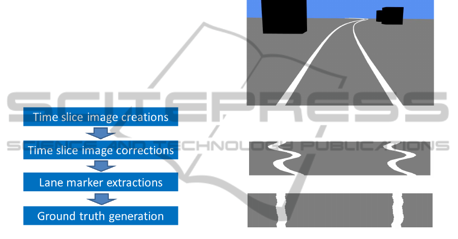
3.2 Process Overview
A video is a set of multiple images taken continu-
ously in time domain. A spatio-temporal image is
three dimensional data that combines images in the
time axis direction. Time slice images are obtained
by cutting away parallel to the horizontal and the
time axis of spatio-temporal image. The time slice
image is composed by stacking a specific rows in
each frame. The vertical axis of the time slice im-
age denotes time domain. This paper proposes an ef-
ficient algorithm which generates ground truth by us-
ing spatio-temporal image. Fig.2 shows the process
overview of the proposed algorithm.
Time slice images are obtained by spatio-temporal
image of a video where a lane exists since our aim
is to generate lane ground truth. Lane width is reg-
ulated by the road traffic law. Ideally driving in a
straight road makes lane markers in all time slice im-
ages straight line. Driving a car usually, however,
meander slightly on the lane. Moreover, roads are
not only straight but also curved. Lane markers in
a time slice image which is obtained from even the
VISAPP2015-InternationalConferenceonComputerVisionTheoryandApplications
456
bottom of the spatio-temporal image, therefore, be-
come wavy. Similarly, lane markers in time slice im-
ages which are obtained from the top of the spatio-
temporal image are affected by both a lane shape and
erratic drive. Thus, the wavy effects by the erratic
drive should be corrected. Lane markers in a time
slice image, which is obtained by the bottom-most im-
age in spatio-temporal image, are corrected to straight
lines. Those are the nearest lane markers to the ve-
hicle. Then, lane marker’s contours are extracted at
the time slice image, and center lines of lane mark-
ers in time slice images are obtained by the contours.
Center lines of lane markers in all time slice images
are obtained by propagating the extracted contours of
lane markers from the bottom-most image to the top-
most image. Lane ground truth is generated by recon-
structed lane markers, which are the obtained center
points in time slice images in a frame.
Figure 2: Process overview.
4 WINDING LANE MARKERS
CORRECTION IN TIME SLICE
IMAGES
Driving a vehicle whilst keeping the center of the lane
is generally difficult. The vehicle, therefore, moves
by slightly meandering against the lane. As a result,
lane markers in time slice images which are obtained
from near the vehicle become wavy ones by the effect
of meandering. Lane markers in time slice images be-
come simple straight lines if a vehicle is always driven
on the center since lane width is uniformly regulated
by the traffic law. Fig.3 shows one frame of a com-
puter generated video. Usually, lane markers in the
time slice image obtained from the bottom-most row
become wavy as shown in Fig.4(a). If it is assumed
that a car moves at the center of the lane, lane markers
are almost straight lines as shown in Fig.4(b). If the
car cruises at the center of the lane, lane markers in
the time slice image obtained from the bottom-most
row as shown in Fig.4(a) become like straight lines as
shown in Fig.4(b). Based on this property, lane mark-
ers in the bottom-most time slice image are corrected
to straight lines. SSD (Sum of Squared Differences)
is employed to correct lane markers. Lane markers
can be approximated to straight lines by minimizing
SSD of adjacent rows in the time slice image with the
formula(1). Time slice image correction is performed
by calculating the minimum SSD for all pairs of adja-
cent rows.
Figure 3: A computer generated image.
(a) Time slice image with general driving.
(b) Time slice image to keep driving in lane’s center.
Figure 4: Examples of synthesis time slice images.
x
s
(t) =
arg min
s
W−1
∑
x=s
(I(x, H −1,t)
−I(x− s, H − 1,t − 1))
2
(s ≥ 0)
arg min
s
W−1−s
∑
x=0
(I(x, H −1,t)
−I(x+ s, H − 1,t − 1))
2
(otherwise)
(1)
where, W and H represent a width and a height of
Region of Interest in an original image illustrated in
Fig.5, respectively. I(x, y,t) denotes a pixel value at a
coordinate (x,t) in a time slice image with height y.
Equations are divided into two cases where a vehicle
moves to the right or the left. The row at t is shifted
by x
s
(t) where the amount error between t and t − 1
is minimized. An original time slice image as shown
in Fig.6(a) becomes close to straight lines as shown in
Fig.6(b).
EfficientGroundTruthGenerationbasedonSpatio-temporalPropertiesforLanePredictionModel
457
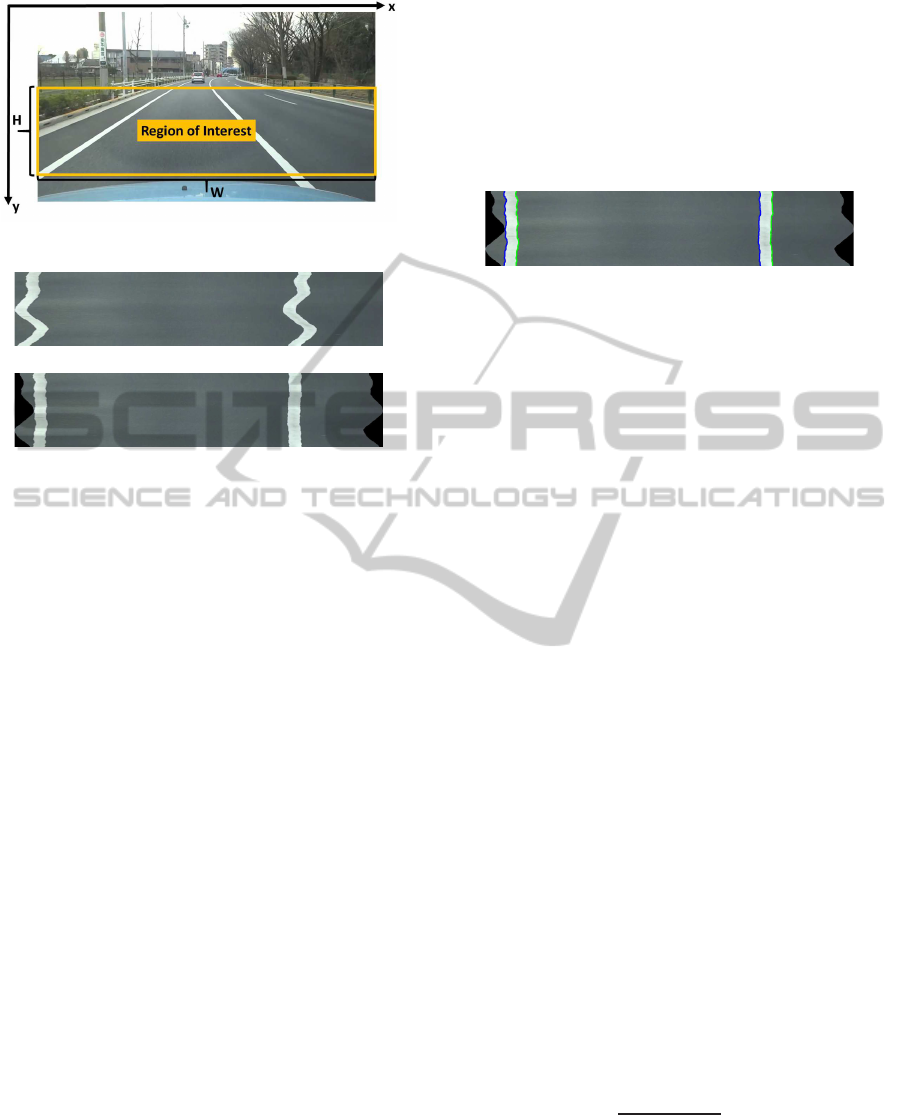
Figure 5: An original image.
(a) A generated time slice image.
(b) A corrected time slice image.
Figure 6: An example of a time slice image correction.
5 GROUND TRUTH
GENERATION BASED ON
SPATIO-TEMPORAL
PROPERTIES
5.1 Lane Marker Region Extraction
Contours are extracted from the corrected time slice
image in order to obtain the center lines of lane mark-
ers. The time slice image obtained from the most bot-
tom row has few noise such as a guardrail by perspec-
tive projection. Therefore, contours of lane markers
in the most bottom row are extracted. Two lane mark-
ers are extracted by applying binarization. Threshold
for binarization is decided by histogram in the time
slice images. It is difficult to extract only lane mark-
ers, if noises remain in the binarized time slice image.
It, however, can be assumed that lane marker regions
are connected from the top-most to the bottom-most
in the time slice image. Contours of the lane markers
are searched by raster scan order. The left lane marker
region is detected by the raster scan which meets a
white pixel for the first time. The right marker re-
gion is detected by the second white pixel except for
pixels in the left line marker region. Then, contours
are extracted by tracing the contours on the two lane
marker regions. The center line of the lane marker is
obtained by using two long sides of the approximately
rectangular lane marker region. Contour search is per-
formed counterclockwise from the start pixel at the
upper left of the region and back to the start pixel
around the region. Here, in order to extract the cen-
ter line of the lane markers in time slice images, only
the contour lines of lane markers in the long side are
used. The extracted contours, which are colored with
blue and green, for a lane are shown in Fig.7.
Figure 7: An example of extracted contours of lane markers.
5.2 Lane Marker Extraction by
Propagating Extracted Lane
Marker
Lane markers mainly have two types a dashed line and
a solid line shape. It is classified in the shape of each
lane width. In this section, extraction method on the
shapes of the two types is discussed.
5.2.1 Solid Line Shape
Contours of lane markers in all time slice images
are extracted by propagating the extracted contours,
which are obtained in section 5.1, from the bottom-
most to the top-most time slice image. Namely, con-
tour points from the nearest against a vehicle to the
farthest one are extracted in a frame. Initial contour
of snakes (Sawano and Okada, 2007) is propagated.
At first, four contour lines of the long sides of the
extracted lane markers in section 5.1 are used as the
initial contour of snakes at y = H − 1, where H − 1
denotes the bottom-most plane in the spatio-temporal
image. Then snakes is applied to the time slice im-
age at y and two lane markers are extracted. In the
same way, extracted contours on time slice image at
y − 1 propagate the time slice image at y + 1 as ini-
tial contours of snakes. Repeating the procedure en-
ables extraction of contours in all time slice images.
Lane markers in all time slice images even in includ-
ing much noise are, therefore, extracted correctly by
this procedure. The center lines of lane markers are
calculated by the following equation(2).
x
L
(t) + x
R
(t)
2
(2)
where x
L
(t) represents x coordinates in the left long
side contour of a single lane marker at t and x
R
(t)
represents that of right long side contour. Fig.8 shows
the extracted center lines.
VISAPP2015-InternationalConferenceonComputerVisionTheoryandApplications
458
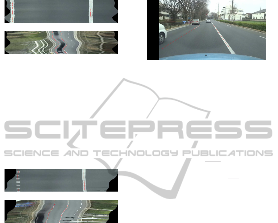
(a) Time slice image at y = 904.
(b) Time slice image at y = 407.
Figure 8: Center lines of solid shape lane makers.
5.2.2 Dashed Line Shape
Dashed line shape detects based on the size of dashed
line region in time slice image of the bottom. Each de-
tected region is obtained center of gravity, and those
points are interpolated by spline interpolation. Then,
the interpolation line is propagated the adjacent time
slice image, extracted region around the interpolation
line distinguished as dashed line. The center line of
all time slice images is obtained by repeating above
procedure.
(a) Time slice image at y = 890.
(b) Time slice image at y = 421.
Figure 9: Center lines of dashed shape lane markers.
5.3 Ground Truth Generation
The center lines of all time slice images obtained by
correcting meandering effect for the time slice image
of the nearest a vehicle, and propagating the extracted
lane marker’s information permits extracting the far-
thest time slice images. All the extracted center lines
are integrated into spatio-temporal image and then
the spatio-temporal image is separated into frames.
Brokar et al. (Borkar et al., 2010) generate center
lines in a time slice image by interpolating points as-
signed manually. Moreover,it is necessary to interpo-
late center lines in space domain again. The proposed
algorithm does not need to interpolate center lines.
The algorithm extracts center lines of lane markers
directly. Generated ground truth images are shown in
Fig.10. Obtained lane markers represent appropriate
lane shape.
Figure 10: Ground truth.
6 EVALUATION
Generated ground truth based on spatio-temporal
properties is evaluated. Ground truth in this eval-
uation is generated manually. Evaluation criteria
(Borkar et al., 2010) given by the following formula
(4) is employed.
λ(y,t) = |G
y,t
− X
y,t
| (3)
E(t) =
H
∑
y=1
λ(y,t)
H
pixel. (4)
(
Correct E(t) <
M
Real
2
Incorrect otherwise
(5)
where, X
y,t
is coordinate x in proposed ground truth
of frame t with height y, and G
y,t
is coordinate x in
ground truth generated by hand of frame t with height
y. λ(y, t) is, therefore, the difference of coordinate x
between these two points. Formula (4) represents the
average of λ(y,t) in a frame. The unit is pixel. Borkar
et al. (Borkar et al., 2010) use formula (5) to evalu-
ate the accuracy of ground truth. M
Real
represents the
number of pixels of real lane markers width. The lane
marker is regarded as correctly extracted when aver-
age error E(t) is smaller than half of M
Real
since the
extracted center line is almost within the actual lane
marker. Lane markers width of the bottom-most in a
frame is 21pixels. Ground truth is also extracted by
using Borkar’s method (Borkar et al., 2010) for com-
parison. Straight and curved roads with continuous
lane markers and dashed line shape are captured, and
dashed line lane markers are calculated the accuracy
of the ground truth of the white line on. The results
are shown in Table1. Three and five time slice images
are used to generate ground truth by using Borker’s
method (Borkar et al., 2010). The average errors are
obtained for 30 frames in each road shape. Examples
of the road conditions and the visibility of the data set
for the evaluation are shown in 11(a) and 11(b).
By comparing the error of the proposed ground
truth with the ground truth generated from three time
EfficientGroundTruthGenerationbasedonSpatio-temporalPropertiesforLanePredictionModel
459
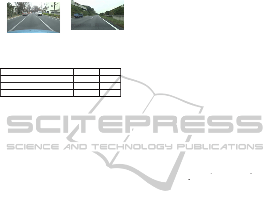
(a)An example of local roads.
(b)An example of highway
roads.
Figure 11: Examples of data set for evaluation.
Table 1: Average of error in a frame(pixels).
Straight Curve
Proposed ground truth 1.44 4.78
Borkar’s(time slice of three) 1.27 5.42
Borkar’s(time slice of five) 1.33 3.66
slice images, we can notice that the error is almost
same for straight roads. The error of the proposed
method is, however, small comparing with the previ-
ous method because the previous one employs inter-
polation with a few control points. The accuracy of
the proposed method is almost same that of the pre-
vious method with five time slice images. The result
shows that the proposed ground truth gets good ac-
curacy for both straight and curved roads. The best
thing is possible to reduce manual operations for ob-
taining lot of lane informations to construct the lane
prediction model.
7 CONCLUSIONS
In this paper, we proposed an offline ground truth
generation method based on spatio-temporal proper-
ties that reduces tedious tasks. Meanering effects on
time slice images are corrected based on the spatio-
temporal properties of lane markers. The proposed
method does not need any interpolation since center
lines of lane markers are generated directly by us-
ing all time slice images. The error of the generated
ground truth becomes small for both of straight and
curved roads. The proposed method will be applied
to the variety of road situations and the limitation of
the method should be discussed. We are planning
to construct precise geometrical lane prediction mod-
els using ground truth generated by this method, and
perform lane detection in low visibility based on the
models.
REFERENCES
Borkar, A., Hayes, M., and Smith, M. T. (2010). An ef-
ficient method to generate ground truth for evaluat-
ing lane detection systems. International Conference
on Acoustics, Speech, and Signal Processing, pages
pp.1090–1093.
Iwaki, Y. and Takahashi, H. (2012). Real-time lane tracking
based on lane feature for low visibility driving. Tech-
nical Report of IEICE, ITS2011-43:pp.159–164.
Linder, P., Richter, E., and Wanielik, G. (2009). Multi-
channel lidar processing for lane detection and esti-
mation. International IEEE Conference on Intelligent
Transportation Systems, pages pp.1–6.
Meuter, M., Muller-Schneiders, S., and Mika, A. (2009). A
novel approach to lane detection and tracking. Inter-
national IEEE Conference on Intelligent Transporta-
tion Systems, pages pp.1–6.
Michael, K., Andrew, W., and Demetri, T. (1988). Snakes:
Active contour models. International Journal of Com-
puter Vision, Vol. 1, Issue. 4:pp.321–331.
Oike, T. (2001). A white road line recognition system us-
ing the model-based method. DENSO TECHINICAL
REVIEW, Vol. 6, No. 1:pp.54–61.
Sasipalli, V. S. R., Sasipalli, G. S., and Harada, K. (1997).
Single spirals in highway design and bounds for their
scaling. IEICE TRANSACTIONS on Information and
Systems, E80–D, 11:pp.1084–1091.
Sawano, H. and Okada, M. (2007). Tracking edges of road
white lines by four snakes. Information Processing
Society of Japan, Vol.48:pp.2868–2873.
TOYOTA MOTOR CORPORATION. Lane
keeping assist system. http://www.toyota-
global.com/innovation/safety
technology/safety tech
nology/technology
file/active/lka.html.
Veit, T., Tarel, J. P., Nicolle, P., and Charbonnier, P. (2008).
Evaluation of road marking feature extraction. Intel-
ligent Transportation Systems, ITSC 2008. 11th Inter-
mational IEEE Conference on:pp.174–181.
Wang, Y. and Teoh, E. K. (2004). Lane detection and
tracking using b-snake. Image and Vision Computing,
Vol.22:pp.269–280.
VISAPP2015-InternationalConferenceonComputerVisionTheoryandApplications
460
