Geometry Batching using Texture-arrays
Matthias Trapp and J
¨
urgen D
¨
ollner
Hasso-Plattner-Institute, University of Potsdam, Potsdam, Germany
Keywords:
Batching, Texture-array Processing, Real-time Rendering.
Abstract:
High-quality rendering of 3D virtual environments typically depends on high-quality 3D models with signif-
icant geometric complexity and texture data. One major bottleneck for real-time image-synthesis represents
the number of state changes, which a specific rendering API has to perform. To improve performance, batch-
ing can be used to group and sort geometric primitives into batches to reduce the number of required state
changes, whereas the size of the batches determines the number of required draw-calls, and therefore, is crit-
ical for rendering performance. For example, in the case of texture atlases, which provide an approach for
efficient texture management, the batch size is limited by the efficiency of the texture-packing algorithm and
the texture resolution itself. This paper presents a pre-processing approach and rendering technique that over-
comes these limitations by further grouping textures or texture atlases and thus enables the creation of larger
geometry batches. It is based on texture arrays in combination with an additional indexing schema that is eval-
uated at run-time using shader programs. This type of texture management is especially suitable for real-time
rendering of large-scale texture-rich 3D virtual environments, such as virtual city and landscape models.
1 INTRODUCTION
Complex virtual environments, especially 3D geovir-
tual environments, such as virtual 3D city and land-
scape models, can often be characterized by a high
number of geometric primitives and a high amount of
texture data (Fig. 2). The increasing (semi-)automatic
generation of such models does not reflect their effi-
cient real-time rendering that is influenced by a num-
ber of limitations.
Texture Batching and Atlases. An important per-
formance limiting factor are API (Application Pro-
gramming Interface) draw-calls that issues streams of
commands from the application, via driver to the GPU
(Graphics Processing Unit) during rendering. To re-
duce the number of draw-calls required, the concept
of batching can be used. Batching denotes the group-
ing of meshes instead of drawing each separately. In
particular, this is efficient for large batch sizes. The
grouping can be performed with respect to differ-
ent criteria, e.g., textures or shader programs that are
shared by meshes. In the context of this paper, a batch
represents a group of rendering primitives that share
the same textures.
To reduce texture state-changes and batch counts,
Wloka (Wloka, 2005) introduces a concept that uses
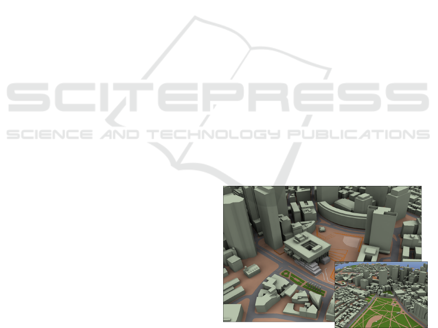
Figure 1: Exemplary application of our batching approach.
The high-detailed virtual 3D city model of Boston com-
prises 864 lighting texture-atlases and is rendered by using
an average batch size of 2,840,158 triangles at speed of 45
frames-per-second.
texture atlases for selecting and packing multiple
batch-breaking textures and packs them into one or
more texture atlases. Afterwards, the texture coordi-
nates (UV mapping or parametrization) of the mod-
els are updated respectively. The field of texture at-
las generation has been well exploited in the recent
years. The developed algorithms work on piecewise
linear surface representations (Velho and Sossai Jr.,
2007), parametric surfaces such as NURBS (Guthe
239
Trapp M. and Döllner J..
Geometry Batching using Texture-arrays.
DOI: 10.5220/0005289902390246
In Proceedings of the 10th International Conference on Computer Graphics Theory and Applications (GRAPP-2015), pages 239-246
ISBN: 978-989-758-087-1
Copyright
c
2015 SCITEPRESS (Science and Technology Publications, Lda.)
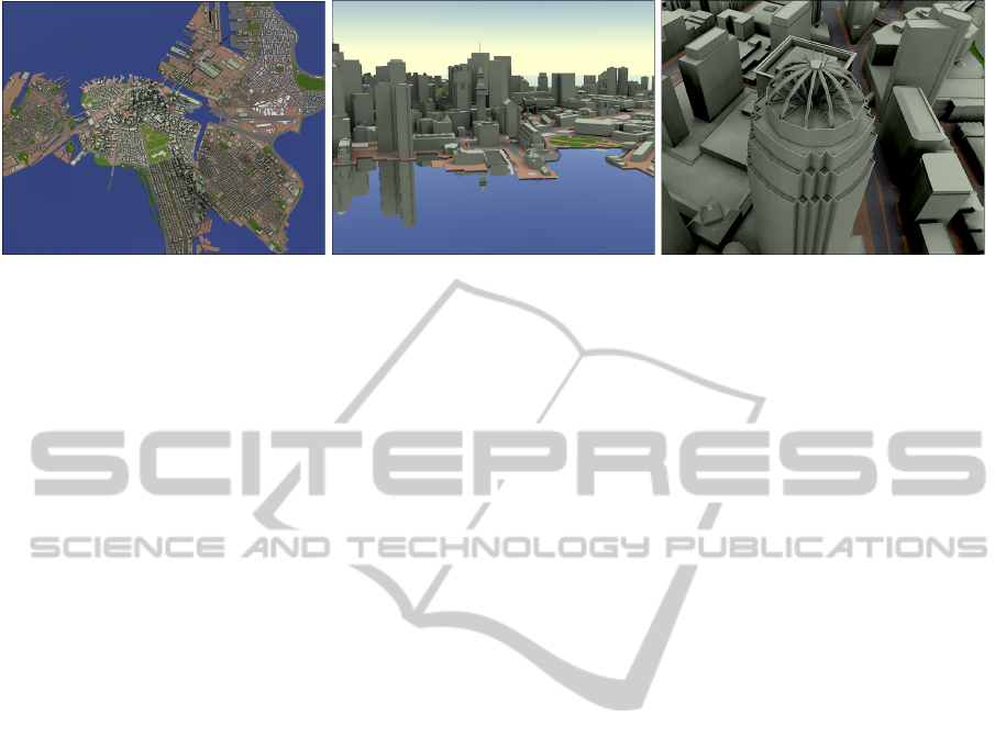
Figure 2: Overview of scenes rendered with the presented texture-array batching approach. The statistics of the geometrical
highly complex scene are described in Table 1. The figure shows the 3D virtual city model of Boston of high geometric detail
completely textured with pre-computed light maps and rendered with dynamic water surfaces.
and Klein, 2003), as well as point-sets (Degener and
Klein, 2007).
Causes of Batch Size Limitations. As GPUs be-
come faster and more flexible to program, it is impor-
tant to facilitate the grouping of geometry into large
batches. This results into fewer draw calls and re-
duced state changes, allowing the GPU to achieve
higher performance. Thus, the main goal is to in-
crease the batch size and, thus, enabling optimal batch
sizes for specific target platforms. Considering tex-
tures, especially texture atlases, the batch size, i.e.,
the number of rendering primitives within a batch, is
limited by the following two conditions that reflects
a space/quality trade-off: (1) the segmentation algo-
rithm for a texture atlas defines how many primitives
of the input model are covered by a texture atlas and
therefore form a batch; and (2) even with optimal seg-
mentation algorithms or texture atlases that are cre-
ated by artists, the number of primitives of an associ-
ated batch is limited by the maximal available texture
resolution.
Batching using Texture-arrays. Batching for per-
formance improvement is not a new idea. The pro-
posed texture-array batching (TAB) approach is based
on texture arrays, a generalization of the cube map
and 3D texture concept. The basic principle of tex-
ture arrays is to minimize batch counts by packing as
many materials as possible into a texture array and
render as much of the scene’s geometric primitive
without the occurrence of texture state-changes. Tex-
ture arrays can further be used for multi-texturing ef-
fects for 3D digital terrain models (Dudash, 2007): in
this approach, the indexing into the layers of a texture
array is hard-coded into the respective shader pro-
grams and thus prevents its general application.
Recent developments in rendering hardware and its
unified programming can be used to overcome the
above limitations by managing texture data and geom-
etry batches using an alternative texture representa-
tion and indexing scheme suitable for programmable
GPUs. The presented approach organizes 2D textures
or texture atlases using arrays that are efficiently rep-
resented on the GPU using 3D textures or 2D texture
arrays. Therefore, it aggregates textures of the same
format and resolution into a single texture array. This
approach has a number of advantages:
State-change Reduction. It enables the application
of the complete texturing setup before rendering
all geometry batches. This reduces the number of
texture state-changes significantly.
No Batch-size Constraints. The estimation and im-
plementation of so-called batch budgets is an im-
portant strategy for applications to ensure real-
time rendering capabilities. Often, these budgets
are planned in the conceptual phase of the appli-
cation design.
Texture Sharing. This is important for hardware-
accelerated geometry instancing. For example,
the diffuse and normal component are global for
a set of columns in a temple model but only the
pre-computed light map (Ray et al., 2003) may
change for each instance.
This approach is especially suitable for 3D scenes
comprising a large number of textures of similar
resolution and format. To summarize, this paper
presents the following contributions to the challenges
described in the above section: (1) it presents a
pre-processing approach and rendering technique for
performing geometry batching using 2D texture ar-
rays which enable the usage of larger batch sizes;
(2) it supports a detailed description of a fully
hardware-accelerated implementation and rendering
using OpenGL and the OpenGL Shading Language;
and (3) it compares the improvement of rendering per-
formance over texture atlases only by means of virtual
3D city models.
GRAPP2015-InternationalConferenceonComputerGraphicsTheoryandApplications
240

The remainder of this paper is structured as fol-
lows. Section 2 reviews existing techniques for tex-
turing and geometry batching. Section 3 introduces
the concept of texture-atlas packing to improve batch
sizes. Section 4 presents details for integration, im-
plementation, and rendering packed texture atlases.
Section 5 discusses the results of our performance
evaluation, the conceptual limitations as well as prob-
lems, and gives ideas for future work. Finally, Section
6 concludes this paper.
2 RELATED WORK
There are different related research projects in the
field of terrain and geovisualization that cover the ren-
dering of large-scale static and dynamic textures us-
ing virtualization as well as out-of-core techniques
and frameworks. However, only few of them focus on
batching as the main application or respect modern
GPU capability for simple implementation and inte-
gration into existing rendering frameworks.
For terrain visualization, multi-resolution mod-
els for terrain textures can be applied (D
¨
ollner and
Baumann, 2000). The rendering algorithm simulta-
neously traverses a multi-resolution geometry model
and a multi-resolution texture model, and takes geo-
metric and texture approximation errors into account.
In contrast to out approach, it uses multi-pass ren-
dering and exploits multi-texturing to achieve real-
time performance. This approach can be extended
for managing multi-resolution textures in multiple
caching levels exhibiting frame-to-frame coherency
(Hua et al., 2004; Okamoto et al., 2008).
With respect to virtual 3D city models, the prob-
lem of large numbers of texture switches and limited
graphics memory was addressed in (Buchholz and
D
¨
ollner, 2005). They present a level-of-detail tex-
turing technique that is based on a hierarchical data
structure of all textures used by scene objects and is
created in a preprocessing step. At runtime, it requires
only a small set of these texture atlases that represent
scene textures in an appropriate size depending on the
current camera position and screen resolution.
In (Boubekeur and Schlick, 2006) an interactive
out-of-core texturing approach is presented that en-
ables interactive modification of large textures using
point-sampled textures at various scales, without re-
quiring additional parametrizations. Therefore, an
adaptive in-core point-based approximated geometry
is required that uses an out-of-core point-sampling al-
gorithm. This approximation is used for interactive
and multi-scale point-based texturing in combination
feature-preserving kernel to convert the point-based
model into a global 3D texture.
Based on previous approaches, sparse virtual tex-
turing (Mittring and Crytek, 2008) simulates large
textures efficiently using less texture memory than
these would actually require. On a per-frame bases, it
uploads only required texture data to video memory.
A fragment shader is used to perform the mapping
from the virtual large texture coordinates to the actual
physical texture coordinates using an indirection tex-
ture. This technique can also be applied to texture for
large quantities of smaller textures (texture atlases).
Taibo et al. present an approach for high reso-
lution, real-time texturing from dynamic texture data
sources (Taibo et al., 2009). An out-of-core texture
visualization uses per-fragment texture LOD com-
putation, is independent from the geometry engine,
and thus can be integrated into existing terrain ge-
ometry engines. Feldmann et al. extend the con-
cept of geometry independent texture clipmaps (Tan-
ner et al., 1998) to handle dynamic texture data (Feld-
mann et al., 2011). Their approach incrementally gen-
erates a clipmap from a large virtual texture of dynam-
ically changing content and extent, using of a tile-
based clip-map approach and spatial indexing data
structure for access.
3 TEXTURE-ARRAY BATCHING
Figure 3 shows an overview to our concept and its
components. It basically consists mainly of three
stages: a pre-processing step (A) generates an input
data structure for our batching algorithm from a num-
ber of given data sets. It extracts texture meshes and
sorts the textures used for these meshes. It further
converts all input meshes into a common format, i.e.,
a common vertex attribute configuration, to facilitate
merging into new batches. Subsequently, the actual
batching process (B) creates new batches of geom-
etry and texture data. It therefore creates a mapping
between newly created geometry batches and their as-
sociated textures, grouped by texture arrays. Finally,
during the rendering step (C), the mapping, which
is basically an additional indirection during the tex-
ture mapping process, is evaluated at run-time using
shader programs.
Preparation of Input Data. The creation of texture
arrays and geometry batches can be performed in a
pre-processing step based on a texture hierarchy. A
texture hierarchy is a data structure that can be de-
rived both from scene graph or manager-based ren-
dering systems. In a scene-graph based rendering sys-
tem, one can assume an implicit texture hierarchy is
GeometryBatchingusingTexture-arrays
241
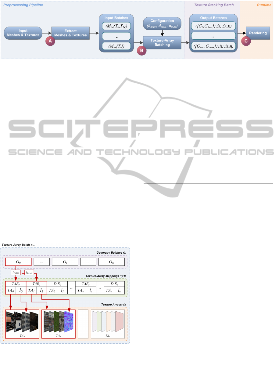
Figure 3: Overview of the pre-propressing and rendering pipeline for the presented batching approach. In an off-line pro-
cessing step the input geometries and texture data are sorted (A) before the actual batching process is performed (B). The
batching process delivers a number of texture arrays, geometry batches, and texture array mappings, which are rendered by
using shader programs (C).
given within the graph. For manager-based render-
ing systems, the texture hierarchy has to be defined
explicitly. We assume that batching with respect to
texture state-changes (e.g. using texture atlases), is
already performed.
Based on the texture hierarchy, we first create a
number of input batches B
I
by sorting in a way that a
input batch B
I
i
= (M
i
, {T
t
}) with B
I
i
∈ B
I
contains a
mesh M
i
and references to all textures T
t
for each tex-
ture unit t that the mesh is using. This structure sim-
plifies the following batching algorithm and ensures
that only textured meshes are considered for batching.
Batching Algorithm. Based on the sorted input
data B
I
, our batching algorithm (Alg. 1) performs
re-grouping of rendering primitives with respect to
the following three parameters, which can be used to
adapt the output to the hardware constraints of dif-
ferent target platforms: (1) the output batch size can
be limited by b
max
primitives. This is useful to adapt
Figure 4: Concept for sampling texture arrays T A at run-
time. Each geometry batch G
i
can reference one or more
array mapping entries TAE
e
within the texture array map-
ping T AM . These entries refer to a bound texture array
TA
e
∈ T A and the respective layer l
e
to sample from (see
Listing 1 for an exemplary GLSL implementation).
the output sizes of vertex buffer objects to apply tech-
niques such as vertex caching (Hoppe, 1999) or to
prevent memory allocation errors during rendering;
(2) choosing the texture array depth d
max
controls the
number of textures within a texture array. A small
value increases the number of output-batches, thus,
the number of draw-calls; and (3) to reflect the si-
multaneously accessible texture units provided by the
rendering hardware, a
max
can be set accordingly to
limit the maximal number of texture-array per output-
batch.
Algorithm 1: Texture-Array Batching.
Require: d
max
> 0 ∧b
max
> 3 ∧a
max
> 0
b ← 0 {set batch size to zero}
for all B
I
i
∈ B
I
do
B
current
← newBatch()
for all T
i
∈ B
I
i
do
5: TA ← matchTextureArray(T A, T
i
)
if layers(TA) > d
max
then
TA ← createNewTextureArray(T
i
)
add(T A, TA)
end if
10: l ← addTexture(TA, T
i
) {Add to array}
TAE ← (TA, l) {Create texture-array entry}
i
TAE
← add(T AM , TAE)
update(B, i
TAE
)
if size(T A) > a
max
then
15: B
O
i
← (B
current
, T A, T A M )
add(B
O
, B
O
i
)
end if
end for
if b + size(M
i
) > b
max
then
20: B
O
i
← (B
current
, T A, T A M )
add(B
O
, B
O
i
)
B
current
← newBatch()
b ← 0
end if
25: B
current
← merge(M
i
, B
current
)
b ← b + size(M
i
) {Update batch size}
end for
GRAPP2015-InternationalConferenceonComputerGraphicsTheoryandApplications
242

For the above parameters a number of output
batches B
O
= B
O
0
, . . . , B
O
m
are created with B
O
i
=
({G
i
}, T A, T AM ). An output batch B
O
i
comprises
the following components: (1) for n given input
batches, the batching process creates a number m of
geometry batches G
0
, . . . , G
m
with m ≤ n; (2) the
original textures are stored into different texture ar-
rays T A = TA
0
, . . . , TA
k
where k ≤ a
max
. Each ar-
ray contains textures of the same resolution. The
texture arrays can have different resolutions: and (3)
the algorithm outputs a texture-array mapping T A M
that basically represents an indirection and is defined
as follows: T AM = TAE
0
, . . . , TAE
n
with TAE
e
=
(TA
e
, l
e
), which is an ordered list of texture-array en-
tries TAE
e
that is generated for each input mesh M
i
. A
texture-array entry is a tuple that stores a reference to
a texture array TA
e
∈ T A and the layer/slice l
e
within
this array (Fig. 4).
The presented algorithm iterates over all given
input batches B
I
i
and constructs texture-arrays by
matching existing textures to texture arrays (Line 5).
The matchTextureArray() function selects a texture
array with the appropriate texture resolution and tex-
ture format. If this criteria cannot be matched, a new
texture-array is created.
4 RENDERING BATCHES
After the presentation of the texture-array batching
concept and algorithm, this section focuses on render-
ing the output batches B
O
(Sec. 4.1). Our prototyp-
ical implementation uses OpenGL with the support
of shader programs and is applicable within a single
rendering pass. Therefore, it is necessary to encode
the texture arrays T A and the texture-array mappings
T AM into suitable GPU data structures (Sec. 4.2).
4.1 Overview of Rendering Algorithm
Based on above representations, the rendering is per-
formed as depicted in Algorithm 2. In contrast to
existing approaches, our rendering technique binds
all textures arrays T A at the start of the rendering
pass (Line 2-4). Following to that, the texture-array
mapping T AM is bound (Line 5). After these state
changes are performed, the algorithm renders all ge-
ometry batches G
i
successively (Line 7-9).
4.2 GPU Data Structures
This section describes the data structures used to en-
able a fully hardware-accelerated implementation
Algorithm 2: Rendering of Texture-Array Batches.
for all B
O
i
∈ B
O
do
for all TA
j
∈ T A do
3: bind(TA
j
) {Texture State-Change}
end for
bind(T AM )
6: bind(Sampler Program) {Sec. 4.3}
for all G
k
∈ B
O
i
do
render(G
k
) {Draw-Call}
9: end for
end for
with a minimal number of texture state-changes. Fig-
ure 4 gives an overview of the components as well as
the respective dependencies.
Texture-array Representation. One choice for
representing 2D texture stacks on the GPU are 3D
textures, whereas an input texture T
i
is stored in a par-
ticular z-slice. The advantage of this approach is the
compliance with older rendering hardware. To avoid
interpolation artifacts between the texture slices, one
has to offset the r component of the 3D texture co-
ordinates. To avoid offsetting, 2D texture arrays are
used for representation. A 2D texture array is similar
to a 3D texture without the bi-linear interpolation be-
tween and with direct access to the z-slices using an
integer layer-index l. Texture arrays can store a num-
ber of 2D texture layers addressed by a single texture
handle. These textures can be updated on a per-layer
basis.
Representation of Texture-array Mappings. A
texture-array mapping T A M is basically represented
as an array of texture-array entries TAE
e
that must be
accessible by a shader program at runtime. Since the
number of texture-array mapping entries depends on
the number of input meshes M
i
and the used texture
units t, their encoding into compile-time shader con-
stants (uniform arrays) would easily exceed the reg-
ister limits of rendering hardware. The presented im-
plementation uses texture buffer objects to encode the
texture array mapping without limitations in length
and size. The encoding is performed on CPU. The
texture array entries TAE
e
are stored successively
within a single texture buffer that is accessed via in-
dexing during shader execution (Listing 1, Line 9).
Representation of Index-mapping. Since the orig-
inal batches M
i
are merged to new batches G
i
, the in-
dex i
TAM
into the mapping T A M must be available
on a per-vertex and per-texture unit basis. The map-
ping representation has to take into account that the
GeometryBatchingusingTexture-arrays
243

texture coordinates of an input mesh M
i
are gener-
ated at run-time (Case A) or already available due to
a prior UV-mapping (Case B). Considering this, there
are mainly two different possibilities to represent the
index i
TAM
: (1) representing the indices for each tex-
ture unit as per-vertex attribute is an effective solution
for Case A and B. However, this has a major disad-
vantage: It introduces a number of additional vertex
buffers as well as the respective stream mappings to
the implementation; alternatively (2) assuming an ex-
isting UV mapping for all input meshes, we can apply
texture-coordinate modification.
To avoid an additional buffer stream mapping and
to simplify the implementation, we choose to store the
index in the z or homogeneous w component of the ex-
isting texture coordinates. Both approaches introduce
only a relatively small memory overhead (Sec. 5.1).
4.3 Sampling of Texture Arrays
After the discussion of the efficient representation of
texture arrays and array mapping on the GPU, we now
present the evaluation of the texture-array mapping
T AM at runtime (Fig. 4). Listing 1 shows an exem-
plary OpenGL shading language (GLSL) source code
for sampling a number of texture arrays T A . Assum-
ing an unified shader model compliant hardware, it
can be used in vertex, geometry, or fragment shader.
The sampling process is performed as follows:
The shader first extracts the indexTAM into the tex-
ture.array mapping (TAM), which is represented by a
texture buffer object. Using this index, the respective
texture array entry (TAE) is fetched, which consists of
the reference in the texture array TA
k
(arrayID) and
the particular layer index l
k
(layerID). To enable an
efficient access to the texture arrays via their respec-
tive samplers, bound to different texture units, we use
an array of sampler that is indexed by the TA compo-
nent of the array mapping entry, e.g., using bindless
textures. Finally, the texture value is fetched from the
indexed texture array using the layer index l
k
and orig-
inal 2D texture coordinates (s,t).
5 RESULTS & DISCUSSION
5.1 Performance Evaluation
Based on the prototypical implementation provided
in the previous section, we tested our approach using
data sets of different geometrical complexities. Table
1 shows the statistical properties of the data sets used
in our performance evaluation (Table 2). The data sets
vary in respect to the number of vertices (#Vertex),
Listing 1: Exemplary GLSL source code for evaluating the
texture-array mapping for a number of texture arrays.
1 uniform samplerBuffer TA M ;
uniform Sam pl ers { sampler2DArray T A [ 25 6]; };
in vec3 t e xC oor d ;
out vec4 c olor ;
6
void m ai n (void)
{// Fetch texture- array mapping
int ind ex TAM = int( te xCo or d . z );
vec2 T AE = texelFetchBuffer( TAM , i nd exT AM ). xy ;
11 // Resolve mapping
int arr ay ID = int( T AE . x );
float lay er ID = TAE .y;
// Compute texture coordinates for sampling
vec3 t Cs = vec3( t exC oo rd .st , la yer ID );
16 // Fetch texture array sampler
sampler2DArray sam pl er =
sampler2DArray( TA [ ar ray ID ] );
// Sample texture array
color = te xtu re ( sa mp le r , t Cs ) ;
21 }
the number of textures (#Texture), as well as the av-
erage batch size of the input meshes (b
average
(B
I
i
))
and output meshes (b
average
(B
O
i
)). The texture atlases
(ambient occlusion light maps) of the test scenes are
the results of an automatic computation process (Mc-
graw and Sowers, 2008).
Test Environment. We use two test platforms to
conduct the performance tests: a NVIDIA GeForce
GTX 680 with 640 MB video memory on an Athlon
64 X2 Dual Core 4200+ with 2.21 GHz and 2 GB of
main memory (test platform 1), as well as a NVIDIA
GeForce GTX 970 on an Intel Core Duo E 8400, with
3GHz and 3.25 GB main memory and 1GB video
memory (test platform 2).
The performance tests are captured at a viewport
resolution of 1600 × 1200 pixels without vertical syn-
chronization and multi-sampling. The 32bit Windows
XP test application does not utilize the second CPU
core. All textures are uncompressed and all input
meshes are not indexed. In our examples, we use
luminance-alpha texture buffers with 32bit precision
to represent the texture-array mappings. The indices
are encoded in the respective texture coordinates.
Performance Results. Table 2 provides the results
of the performance comparison. Except the test data
set A, which comprises two geometry batches, our ap-
proach enables the storage of all input meshes within
a single geometry batch. The measurements show
an average speed-up of 11.1 for test platform 1 and
an average speed-up of 2.8 for test platform 2. This
is caused by the different CPU speeds of the test-
platforms. However, the non-batched version of test
scene A could not be rendered in real-time on both
platforms, so the impact on the speed-up factors was
GRAPP2015-InternationalConferenceonComputerGraphicsTheoryandApplications
244

Table 1: Geometrical and batch complexity of the used test data sets.
Dataset #Vertex #Texture b
average
(B
I
i
) b
average
(B
O
i
) O
T A M
A 5,680,317 864 6,735 2,840,158 2,592
B 1,768,374 204 8,668 1,768,374 702
C 1,040,503 269 3,868 1,040,503 807
D 103,788 14 7,413 103,788 42
not taken into account. Following to the comparison,
our approach is especially suitable for a high number
of textures that bound small geometry batches respec-
tively.
Table 2: Performance comparison of the rendering speed
in frames-per-second (FPS) between batched (w) and non-
batched (w/o) scene representations.
FPS 8800 GTS FPS GTX 280
Scene w/o TAB w TAB w/o TAB w TAB
A 0.0 45.0 0.3 98.4
B 9.1 85.3 23.8 188.3
C 8.9 156.2 22.9 319.5
D 66.7 427.4 203.7 561.8
Memory Requirements. The additional memory
required for the texture-array mapping depends lin-
early on the number of input meshes M
i
and their tex-
ture units units(M
i
). The space complexity O
T A M
for
all generated array mappings can be computed by:
O
T A M
(n) =
∑
n
i=0
p · units(M
i
) with M
i
∈ B
I
i
. The
value of the coefficient p depends on the additional
texture coordinate to index a TAE, as well as the used
precision for the texture-array mapping values TA
e
and l
e
. The space complexity for each of the test data
sets is displayed in column six in Table 1.
5.2 Limitations & Future Work
The presented concept is not of a general nature. It
mainly profits from uniform texture resolutions and
formats. Under these assumptions, which are usually
the case in most gaming applications, the approach
can be used to accelerate rendering as described in
the above sections. However, the concept has a num-
ber of limitations that prevent its broader application.
For a high number of input meshes with varying tex-
ture resolutions and formats, the number of texture
arrays increases and may exceed the number of avail-
able hardware texture bindings offered by bindless
texturing functionality. Further, our approach cur-
rently supports only 2D texture targets but can easily
be extended.
For future work, we would like to extend our
approach to support view-dependent multi-resolution
texture atlases (Buchholz and D
¨
ollner, 2005). There-
fore, the array mapping must be extended to support
transformation matrices for the respective texture co-
ordinates. Further, we like to add repeat or mirror
warp modes for texture coordinates and atlases to en-
able our approach to render generic textured or proce-
dural generated 3D virtual city models. Furthermore,
we strive towards the support of 1D and 3D volumet-
ric textures. In the latter case, the array mapping can
be extended with a start- and end-layer ID. In contrast
to 2D textures, the texture array mapping may need
resorting of the texture array contents, which can re-
sult in heavy computational overhead at run-time.
6 CONCLUSIONS
This paper presents an approach for batching geom-
etry based on texture arrays. It facilitates a flexible
partitioning of geometry, i.e., the choice of geometry
batch size, which is now only limited by the avail-
able video memory, as well as the reduction of texture
state-changes during rendering. The proposed imple-
mentation shows a significant increase in rendering
speed due to an optimal utilization of the GPU that is
documented in a performance evaluation and compar-
ison.
ACKNOWLEDGEMENTS
The authors would like to thank the anonymous re-
viewers for their valuable comments. This work
was funded by the Federal Ministry of Education
and Research (BMBF) within the InnoProfile Trans-
fer research group ”4DnD-Vis” (www.4dndvis.de).
The 3D virtual city model of Boston is pro-
vided by the Boston Redevelopment Authority
(www.bostonredevelopmentauthority.org).
GeometryBatchingusingTexture-arrays
245

REFERENCES
Boubekeur, T. and Schlick, C. (2006). Interactive Out-Of-
Core Texturing Using Point-Sampled Textures. In EU-
ROGRAPHICS Symposium on Point-Based Graph-
ics, Boston United States. I.: Computing Method-
ologies/I.3: COMPUTER GRAPHICS/I.3.7: Three-
Dimensional Graphics and Realism/I.3.7.1: Color,
shading, shadowing, and texture.
Buchholz, H. and D
¨
ollner, J. (2005). View-Dependent Ren-
dering of Multiresolution Texture-Atlases. In Pro-
ceedings of the IEEE Visualization 2005, pages 215–
222.
Degener, P. and Klein, R. (2007). Texture atlas generation
for inconsistent meshes and point sets. In SMI ’07:
Proceedings of the IEEE International Conference on
Shape Modeling and Applications 2007, pages 156–
168, Washington, DC, USA. IEEE Computer Society.
D
¨
ollner, J. and Baumann, K. (2000). Texturing techniques
for terrain visualization. In Proceedings of IEEE Vi-
sualization, pages 227–234.
Dudash, B. (2007). Texture arrays terrain rendering. Tech-
nical Report WP-03015-001, NVIDIA Corporation.
Feldmann, D., Steinicke, F., and Hinrichs, K. H. (2011).
Flexible clipmaps for managing growing textures. In
In Proceedings of International Conference on Com-
puter Graphics Theory and Applications (GRAPP.
Guthe, M. and Klein, R. (2003). Automatic texture at-
las generation from trimmed nurbs models. In Eu-
rographics 2003.
Hoppe, H. (1999). Optimization of mesh locality for trans-
parent vertex caching. In SIGGRAPH ’99: Pro-
ceedings of the 26th annual conference on Computer
graphics and interactive techniques, pages 269–276,
New York, NY, USA. ACM Press/Addison-Wesley
Publishing Co.
Hua, W., Zhang, H., Lu, Y., Bao, H., and Peng, Q. (2004).
Huge texture mapping for real-time visualization of
large-scale terrain. In Proceedings of the ACM Sym-
posium on Virtual Reality Software and Technology,
VRST ’04, pages 154–157, New York, NY, USA.
ACM.
Mcgraw, T. and Sowers, B. (2008). Hardware acceler-
ated per-texel ambient occlusion mapping. In ISVC
’08: Proceedings of the 4th International Symposium
on Advances in Visual Computing, pages 1115–1124,
Berlin, Heidelberg. Springer-Verlag.
Mittring, M. and Crytek (2008). Advanced virtual tex-
ture topics. In ACM SIGGRAPH 2008 Games, SIG-
GRAPH ’08, pages 23–51, New York, NY, USA.
ACM.
Okamoto, R. M., de Mello, F. L., and Esperanc¸a, C. (2008).
Texture management in view dependent application
for large 3d terrain visualization. In Proceedings of the
2008 Spring Simulation Multiconference, SpringSim
’08, pages 641–647, San Diego, CA, USA. Society
for Computer Simulation International.
Ray, N., Ulysse, J.-C., Cavin, X., and Levy, B. (2003). Gen-
eration of radiosity texture atlas for realistic real-time
rendering. In Eurographics, Granada, Espagne.
Taibo, J., Seoane, A., and Hern
´
andez, L. (2009). Dynamic
virtual textures. Journal of WSCG, 17(1-3):25–32.
Tanner, C. C., Migdal, C. J., and Jones, M. T. (1998). The
clipmap: A virtual mipmap. In Proceedings of the
25th Annual Conference on Computer Graphics and
Interactive Techniques, SIGGRAPH ’98, pages 151–
158, New York, NY, USA. ACM.
Velho, L. and Sossai Jr., J. (2007). Projective Texture Atlas
Construction for 3D Photography. Visual Computer,
23(9):621–629.
Wloka, M. (2005). ShaderX3, chapter Improved Batching
Via Texture Atlases, pages 155–167. Charles River
Media.
GRAPP2015-InternationalConferenceonComputerGraphicsTheoryandApplications
246
