
Automatic Variable-timing Animation Transition based on Hierarchical
Interpolation Method
Yumeng Wang
1,2
, Fubo Lang
1
, Zheng Wang
1,2
and Bo Xu
1
1
Interactive Digital Media Technology Research Center, Institute of Automation,
Chinese Academy of Sciences, Beijing, China
2
Zhejiang Institute of Digital Media of Chinese Academy of Sciences, ShaoXing, China
Keywords:
Animation Transition, Interpolation, Variable Timing, Character Animation.
Abstract:
Character animation has been used in many fields, such as film making, virtual reality interaction and video
games. Video game needs a large set of character animations for users to trigger. However, it is a complex and
tedious work for animators to manufacture all the transition animations between each pair of character anima-
tions. In this paper, a novel rapid method is presented to generate transition animation automatically. Firstly,
animations in the game animation set are classified. Secondly, the time length during motion interpolation is
calculated automatically, which is decided by the angle velocity of character’s joints. The method is called
variable timing method. Lastly, by using hierarchical interpolation method, postures interpolate between dif-
ferent animations. The transition animation can be quickly acquired, according with human dynamics. In this
way, we can get a natural movement by connecting animations together. Experimental results demonstrate
that our method can be effectively and efficiently applied to generate transition animations between various
character animations.
1 INTRODUCTION
Interactive entertainment is a significant application
of virtual character animation. There are two stan-
dards to evaluate the quality of interactive games,
the reality of immersion and the real-time response.
Nowadays, there are a large number of role-play video
games, they need to create a lot of character anima-
tions for virtual characters.
When a user trigger an animation, the player in
game will respond accordingly. The character needs a
period of transition animation, while its motion trans-
forms from one to another. There are several solutions
for transition animation as follows.
The first approach is to connect two animations
directly, without any transition animation. This is the
most convenient and efficient way, however,the worst
user experience. This approach directly connect the
last frame of former animation and the first frame of
next animation on the spot. This movement is very
stiff and unreal.
The second approach is the most common method
in the video game industry nowadays. The game will
have a large animation set for users to invoke while
playing the game. The animation set includes all the
character animation, as well as all the transition an-
imation between each animation, which is made by
animators. This approach brings animators a lot of
work, especially when story line of the game is com-
plex. It is also impossible for animators to make all
the transition animation between each two frames. In
this case, the animation will run until one frame there
has a transition animation, leading to time delay.
The third approach is to set a precise time length
for animation blending. In this way, the anima-
tion transition will generate automatically by blend-
ing some keys to overlap these two animations. The
blend time is set previously, it uses the same transition
method for different animation, other than according
to the varied degree of complexity between two dif-
ferent postures.
In this paper, a novel method is presented to solve
these problems above. Firstly, the time length of tran-
sition will be calculated according to the differences
between postures. We call it variable timing method
for the time length is variable. It is a priori to adapt
to the speed of every joint’s movement. And then,
animation transition is generated by rotation interpo-
lation and position prediction according to animation
trend. Different from other methods, this is a hier-
309
Wang Y., Lang F., Wang Z. and Xu B..
Automatic Variable-timing Animation Transition based on Hierarchical Interpolation Method.
DOI: 10.5220/0005264703090316
In Proceedings of the 10th International Conference on Computer Graphics Theory and Applications (GRAPP-2015), pages 309-316
ISBN: 978-989-758-087-1
Copyright
c
2015 SCITEPRESS (Science and Technology Publications, Lda.)
Present
animation
Next
animation
Animation
Classification
Interpolation
method
Hierarchical
interpolation
input
Transition
animation
output
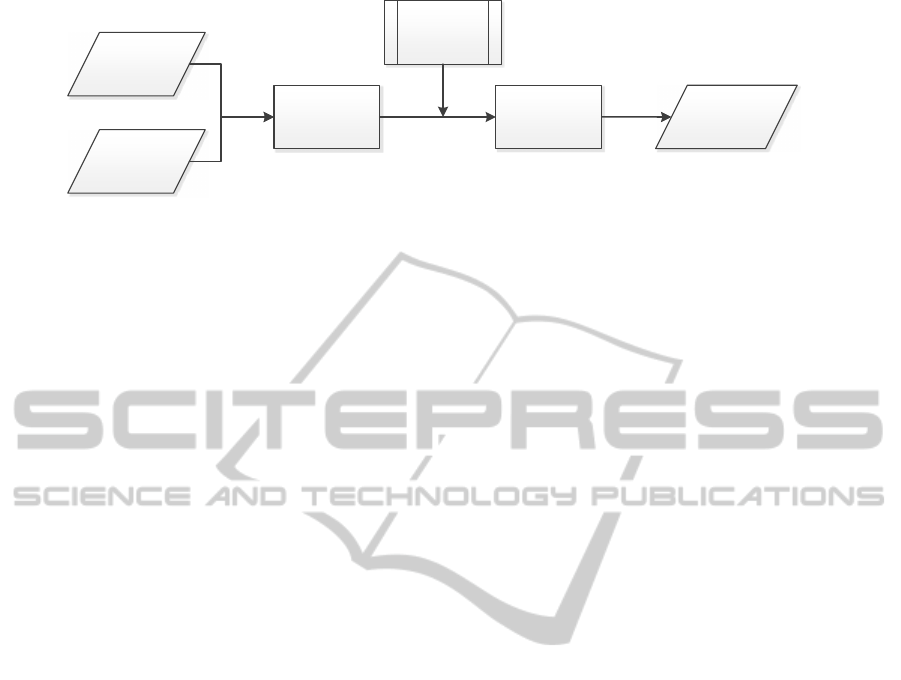
Figure 1: The pipeline of our method.
archical interpolation method, which is based on the
classification of animations and joints. Different in-
terpolation method is used for different joints. At
the same time, according to animation classification,
different interpolation parameter is used for different
types of movement. In the premise of smoothness, it
can improve the calculation speed, by using the hi-
erarchical interpolation method. The pipeline of our
method is show in Figure 1. This paper will explain
all these in detail in later section.
2 RELATED WORK
Common interpolation method of character animation
is described in (Smith, 2013). There are some exten-
sions for interpolation method. (Patil and Chai, 2014)
was used for interactive real time applications and
predefined animations. (Chakra and Li, 2009) pre-
sented a level of details technique applicable to artic-
ulated characters in real-time graphical interpolation
simulation. (Kong et al., 2011) presented the inter-
polation method showed more motion details, which
was based on key frame classification and the synthe-
sis of animations.
Motion interpolation allows constraints to be sat-
isfied. The constraints of (Chai and Hodgins, 2007)
were user-defined, it synthesised the constraints with
motion. (Safonova and Hodgins, 2007) combined
interpolation and motion graphs. (Moulard et al.,
2013) integrated spatial and dynamic constraints for
humanoid character. (O’Brien et al., 2011) showed
space-time vertex constraints to adapt the animation,
the motion adaptation describes constraints of dynam-
ics and kinetics. (Yumeng et al., 2014) provided the
method to optimize the control of motion trajectory.
The posture of character involves the descriptions
of the orientation and position of each segment (Ben-
itez, 2007). An approach for motion simulation which
is driven by data was introduced by (Wang et al.,
2008), which was based on Gaussian process models
for motion generation. (Sok et al., 2010) described a
method of editing motions by interacting directly with
the momentum along particular axes. (Kuznetsova et
al., 2013) generated completely new meshes and mo-
tion and a specific motion for a given mesh or a spe-
cific shape using an existing motion. (Shapiro and
Feng, 2013) associated physical properties with char-
acter’s joint to visualize explicitly a number of proper-
ties that can help animators develop high-quality ani-
mation.
There are some researches about proper duration
of transition. (Wang and Bodenheimer, 2003) ad-
dressed what kind of cost function should be used to
assure smooth transitions between primitives. They
also studied the optimal duration for a transition given
a previously learned distance measure (Wang and Bo-
denheimer, 2004) . (Shum et al., 2009) developed
a method to determine appropriate timings for mo-
tion transition by considering momentum preserva-
tion. (McCann and Pollard, 2007) could pre-compute
optimal transitions based on character state for kine-
matic controllers.
3 DATA PREPARATION
Animation set includes a mass of character anima-
tions, which has already been provided by animators.
Players can trigger different animations during the
video game. In order to get prepared for the creation
of transition, all these animations need to be classi-
fied.
When a new character input into the interface of
video game, the first thing is to traverse all the joints.
Based on the character structure, pivotal joints are
recognized and marked, especially the joints of hip
and feet. These joints will be set as basis of anima-
tion classification.
XOY plane is defined as the ground plane, charac-
ters will play on this plane. Axis Z is defined as the
world up vector, which is perpendicular to the ground.
All these animations can be classified into three
parts.
1. Animation on the spot. The change of the dis-
placement of feet in Axis X and Axis Y is not above
GRAPP2015-InternationalConferenceonComputerGraphicsTheoryandApplications
310

Figure 2: The example of animation classification.
a certain threshold. It can be recorded as ∆X
foot
→ 0
and ∆Y
foot
→ 0. Many motions such as squat, stand
up, applause, shoot and so on, can fall into this cate-
gory.
2. Plane motion. These animations have appar-
ent movement on the XOY plane, as well as the hip’s
value of the Axis Z is no more than original value. It
can be recorded as ∆Z
hip
< δ. Such as walking and
running.
3. Space flight. These animations include the sit-
uations that both feet leave the ground, such as danc-
ing and jumping. These motion would constrained by
the physical properties of anthropometric kinematics.
These animations is classified by the position of feet,
which are both off the ground for a period of time. It
is recorded as Z
foot
> 0.
As show in Figure 2, the left picture shows the
character stands on the ground and shakes his head
proudly, this belongs to the animation on the spot.
The middle picture shows the character walk along
in a direction, this is a walk cycle along Axis X di-
rection, which represents as plane motion. The right
picture is a complicated dance movement, which has
a lot of jumps and flight parts, belonging to the third
category, space flight.
All the animation data has already been classified
before the on-the-fly generation of transition anima-
tions. The transformation between different move-
ments is distinct.
4 AUTOMATICALLY SET THE
TRANSITION TIME LENGTH
For the stability of interactive entertainment, and
good user experience, our method not only need
smooth animation transition, but also the real-time re-
sponse. The transition animation needs to generate
rapidly and smoothly during a tiny time that user does
not perceive.
The time length of the transition animation in our
method can be automatically set. The variable time
length is calculated in real-time automatically. It is
decided by the angular velocity of every joint and the
movement of the character.
The animation transition between two animations
should be smooth. Sudden changes in movement and
appearance would make users edgy and reduce users’
experience.
Some transition method sets an exact blend time.
If there are huge differences between two postures
and the blend time is improper, the method may also
generate a sudden change.
In our research, a variable timing method is raised
to solve the problem of cohesive movement is not
smooth. This method automatically generate a time
length, neither present sudden change, nor take too
long time.
For a biped character, the motion of legs and feet
plays a decisive role in character motion rhythm. To
simplify the calculational complexity, we only take
joints of legs and feet to calculate transition time
length. In addition, hip is the root joint, the rota-
tion of hip is also need to be calculated. These joints
are marked through the traversal of character skeleton
structure. They are numbered with i, and N is the total
number.
As show in Eq. 1, angular acceleration of every
joint is calculated. i represents different joints, n rep-
resents different segmentation of animation. To gen-
erate the transition animation, n = 1 is the present
movement, n = 2 is the next movement.
˙
ω is the an-
gular acceleration,
~
P is a unit vector of rotation axis,
¨
θ is the second derivative of rotation angle θ.
˙
ω
in
=
~
P
in
¨
θ
in
(1)
During the transition animation, angular accelera-
tion is set as a constant, as show in Eq. 2.
˙
ω
i1
is the
angular acceleration of the last frame of the present
animation. ω
i1
is not the last frame of the whole an-
imation, it is the present frame that user triggers the
next movement of the character.
˙
ω
i2
is the angular ac-
celeration of the first frame of the next animation.
˙
ω
i
is a vector to sum these two.
˙
ω
i
=
˙
ω
i1
+
˙
ω
i2
(2)
The time length could be calculate as Eq. 3.
The duration of time length is to divide rotation an-
gle by angular velocity. ∆θ
i
can be obtained from
Eq. 4, which is the joint’s rotation angle between two
frames. θ
i1
is the angle of last frame of the present
animation, θ
i2
is the angle of first frame of the next
animation. ω
i
can be obtained from Eq. 2.
t
i
= ∆θ
i
· ω
−1
i
(3)
∆θ
i
= arccos(θ
i1
· θ
i2
) (4)
The methods to calculate the time length of every
joint, ensuring the velocity of each joint can adapt to
AutomaticVariable-timingAnimationTransitionbasedonHierarchicalInterpolationMethod
311

the movement rhythm of the whole body. As we get
all the possible time length of the joints’ movement,
proper time length for the transition animation needs
to be chose. The maximum value of t
i
is chose as
the time length T, as show in Eq. 5, every joint needs
to display an appropriate movement. We do not ex-
pect the time length leads to an inappropriate sudden
change of any joint.
T = max{t
i
|i ∈ N} (5)
In this way, the time length of the transition can be
automatically obtained in real-time. The time length
T will be used in the interpolation between anima-
tions.
5 HIERARCHICAL
INTERPOLATION METHOD
The motion offers by animators is based on data, we
call it data-driven key frame animation. The inter-
polation between key frames can provides real-time
character animation.
The key pose contains the rotation data of each
joint and the position data of the root node. Different
interpolation methods is used between rotation data
and position data. The transition frame is triggered
by the users, whenever they want, and whatever the
pose is. All the interpolation method and interpola-
tion parameter is chose hierarchically.
5.1 Rotation Interpolation Method
Rotation data is expressed as quaternions, the most
widely used method is Linear Quaternion interpola-
tion (Lerp). the interpolation curve can be stated as
Eq. 6.
Lerp(q
1
,q
2
;h) = q
1
(1− h) + q
2
h (6)
In the equation, q
1
is the quaternion of the current
frame, q
2
is the quaternion of the first frame of the
next movement, h ∈ [0,1] is interpolation parameter.
This is a linear combination of the two quaternions.
Even though the interpolation curve of Lerp can
be quickly and easily used, the velocity graph is not
intuitively satisfied. During the middle part of the in-
terpolation, the curve do not match the unit sphere
very well. On the other hand, the projection of the
interpolation onto the hyper sphere does not generate
constant speed, resulting non-constant angular veloc-
ity. The interpolation function has larger velocity in
the middle of the curve.
To solve this problem, the interpolation method
should yield constant angular velocity. It is called
Spherical Linear Quaternion interpolation (Slerp), as
show in Eq. 7. The interpolation path can be proved to
be the shortest path between two points over the hyper
sphere. Since the angle between the two quaternions
is linearly interpolated, Slerp provides constant angu-
lar velocity.
SLerp(q
1
,q
2
;h) =
sin(1 − h)θ
sinθ
q
1
+
sinhθ
sinθ
q
2
(7)
As show in Eq. 7, θ = arccos(q
1
· q
2
) is the angu-
lar separation of the two quaternions, h ∈ [0, 1] is the
interpolation parameter.
When interpolating between two rotation data, the
Slerp is optimal, however, when interpolating be-
tween a series of rotation, there emerge some prob-
lems. The interpolation curve may not smooth at the
control points, and the angular velocity is not contin-
uous at the control points.
Even though our interpolation is between two key
frames, the final animation should be smooth during
the whole path. Therefore, the movement of present
animation and next animation need to be considered.
Not only the frame before the present frame, but also
the frame after the end frame of transition need to be
used.
When interpolating between a series of control
points, the curve can be constructed by Bezier curves.
As show in Eq. 8, it is the Spherical Spline Quaternion
interpolation (Squad), i is the present frame, i+ 1 is
the next frame, i − 1 is the frame before the present
frame, s can be calculated by Eq. 9.
Squad (q
i
,q
i
+ 1, s
i
,s
i
+ 1;h) = SLerp(SLerp
(q
i
,q
i+1
;h), SLerp(s
i
,s
i+1
;h);2h(1− h))
(8)
s
i
= q
i
·exp
−
log
q
−1
i
q
i+1
+ log
q
−1
i
q
i−1
4
!
(9)
Squad is similar to Bezier curve, but involves
spherical linear interpolation instead of simple linear
interpolation. As it shows that, Squad is derived from
Slerp. In this way, the interpolation is under influence
of the previous movement and the next movement.
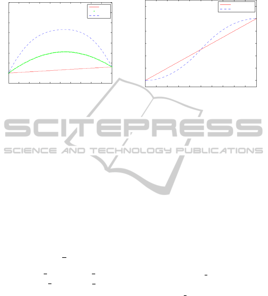
Figure 3 compares all these interpolation methods.
The data-based character animation contains rota-
tion data of all the joints. The rotation interpolation is
used in every joint of the skeleton structure, including
the hip, which is the root node of the skeleton. The
root node is also an important joints in rotation inter-
polation.
GRAPP2015-InternationalConferenceonComputerGraphicsTheoryandApplications
312
0 0.1 0.2 0.3 0.4 0.5 0.6 0.7 0.8 0.9 1
30
40
50
60
70
80
90
100
110
timeline
Lerp
Slerp
Squad
Figure 3: The comparison of different interpolation method.
5.2 Interpolation Parameter
The interpolation parameter h needs to be set. the key
frames can be separate into two categories by the vari-
able motion of joints. We call it common key frames
and variable speed key frames.
The common key frames are mainly used for pre-
sentation of joint movement as a constant speed. The
variable speed key frames are used as non-constant
speed. The difference of the two interpolation param-
eter is show in Figure 4.
Some transformation angle of key frames in the
motion sequence is large . The process of transforma-
tion is speed up first and then slow down again, which
is in accordance with normal human body kinematic
law, and laws of physics. Any transformation from
one state to another requires a force process that is a
process from acceleration to deceleration. The main
function of variable speed key frames is to enhance
the details of velocity change.
h =
t
c
T
(10)
h =
(
2
t
c
T
2
t
c
<
T
2
−2
t
c
T
− 1
2
+ 1 t
c
≥
T
2
(11)
For the common key frames, the interpolation pa-
rameter h shows as Eq. 10; for the variable speed key
frames, the interpolation parameter h shows as Eq. 11.
t
c
is the current time, T is the total interpolation time
as calculate in Eq. 5.
5.3 Hierarchical Interpolation Method
Based on Motion Classification
To express more detail information, our method uses
different interpolation algorithm for different anima-
tion. This is the hierarchical interpolation method
0 0.1 0.2 0.3 0.4 0.5 0.6 0.7 0.8 0.9 1
0
0.2
0.4
0.6
0.8
1
1.2
common
variable speed
Figure 4: The comparison of interpolation parameter.
based on motion classification. Each joint is inter-
polated separately, which can realize different kinds
of animation interpolation respectively and enhance
details of movement.
To generate transition animation rapidly, our hier-
archical interpolation method learned from the level
of detail technique. With the classification of joints
and animations, different interpolation methods are
used.
5.3.1 Interpolation Method Selection
As a couple of similar movements, the transition
needs not to use complexityinterpolation method. For
the transition time will be calculate really small, it is
really difficult to distinguish the transition is good or
bad. In this case, we prefer to use the simple interpo-
lation method to save time.
On the other hand, for a complex movement, in-
terpolation method needs to present better motion de-
tails. Since the transition movementhas a longer tran-
sition duration, the motion details could be easier to
unfold before the eyes of users.
As we discussed, angle offset ∆θ of all joints need
to be calculated. We choose
π
6
as the threshold value,
they can be separated into normal rotation and large
angle rotation. If a joint needs to rotate a large angle,
which means ∆θ ≥
π
6
, we call it large angle rotation.
For large angle rotation, we use Squad interpolation
method, and for normal rotation, we use Slerp inter-
polation method.
All the joints discussed above do not include the
joints of fingers. By traversing the character skele-
ton structure, the joints of fingers have been marked.
the movement of the fingers is tiny to the whole body
movement, therefore, we use the simple Lerp inter-
polation method with the simple linear interpolation
parameter as Eq. 6, to save time.
AutomaticVariable-timingAnimationTransitionbasedonHierarchicalInterpolationMethod
313

5.3.2 Interpolation Parameter Selection
The classification of the animation set is described in
section 3. All the animations have already separated
into three parts, animation on the spot, plane motion
and space flight.
Transition animation between animations on the
spot needs to be simply and quickly generated. We
just use common key frames interpolation parameter,
as Eq. 10.
Except for the transition between two animations
on the spot, all the other animation transition can be
classified as complex transition animations, such as
the transition between space flight, transition between
plane motion, transition between plane motion and
space flight, transition from animation on the spot to
space flight and so on. In order to satisfy the behaviors
and kinematics of human beings, the variable speed
key frame interpolation parameter is used for all these
movement, as show in Eq. 11.
5.4 Position Interpolation
Only the root node has the position data, which de-
cides the global position of the character. According
with human dynamics and motion trend, the trans-
formation of the root node is essential to generate a
proper transition animation .
Animators could not know the current character
global position while playing a video game. There-
fore, animator provides character animations based on
local displacement coordinates. For this reason, the
character’s start frame of next animation needs to set
global position firstly. The position of the character
movement trajectory should conforms to the charac-
ter motion trend and physical properties.
Except for animations on the spot, the character
may have a movetrend, while the character is moving.
Therefore, the position of the last frame of present
animation and the position of the first frame of next
animation should not be simply set as the same point.
The global position of the next animation should be
set as the position after transition animation.
The movement trajectory should be physically
correct. For an transition animation between plane
motions, the position could be calculate as Eq. 12. p
0
is the position of start frame, v is the velocity of start
frame of transition,
˙
v is the acceleration of the start
frame of transition, t
c
is the current time during the
total time T.
p(t
c
) = p
0
+ t
c
v+
1
2
t
2
c
˙
v (12)
For a transition animation involving space flight
animation, we not only need to consider the plane mo-
tion trend, but also the acceleration of gravity. The
position could be calculate as Eq. 13, g is the gravity,
k
g
is the parameter of gravitational acceleration.
p(t
c
) = p
0
+ t
c
v+ k
g
t
2
c
g (13)
6 RESULTS
By applying our method onto the animation set to ob-
tain the animation transition. The process of transfor-
mation from one movement to another could start at
any frame.
As show in Figure 5, it is the transition animation
from walk to stand. While the character is walking
along, the user can trigger to stand pose at any time,
we choose four different movements during walking
arbitrarily. The animation finally transform to the
stand pose with his hands on his waist, as the right-
most picture of each row in Figure 5.
Our method is not only suitable for simple anima-
tion transition, but also suitable for complex anima-
tion transition. As show in Figure 6, it is the transi-
tion animation from dance to run. While the virtual
character is dancing, the user could trigger to the next
animation, such as running, at any frame. There is
no need to wait the finish of the dance movement, a
smooth transition animation to the next animation is
generated automatically. We choose four frames from
dancing animation arbitrarily, as show in the four left-
most picture of each row in Figure 6. The dancing
animation we choose for experiment is complex, in-
cluding running, jumping, rotating and so on. The
first frame of next animation can be seen as the final
posture of the transition animation, which is the right-
most picture of each row in Figure 6. Even though
the movement shows in different perspective in the
screenshot, they are the same movement. The creation
of transition animations between all these animations
are proved to be available.
It is proved by experiments, our method could ap-
ply on all the animations to generate transition anima-
tion at any time. The transition can generate quickly
and automatically. Meanwhile, the transition anima-
tion conforms to human body dynamics, and adapts
to the previous and the next animation trend. This al-
lows users to get more realistic experiences.
7 CONCLUSIONS
In this paper, we have presented a novel method
to generate the transition animation rapidly and
smoothly. It can calculate transition time length by
GRAPP2015-InternationalConferenceonComputerGraphicsTheoryandApplications
314
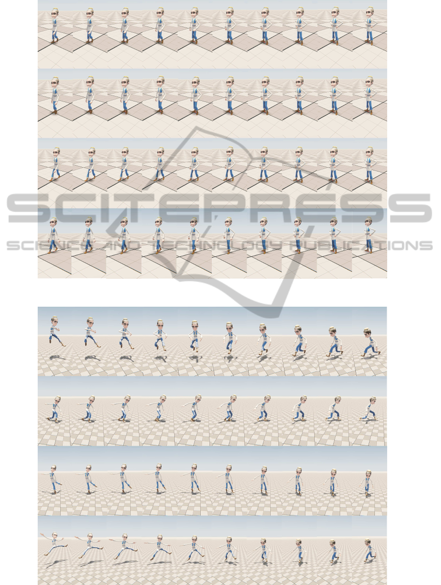
Figure 5: The transition animation from walk to stand.
Figure 6: The transition animation from dance to run.
AutomaticVariable-timingAnimationTransitionbasedonHierarchicalInterpolationMethod
315

using variable-timing method. Therefore, the time
length can be obtained automatically according to dif-
ferent motion complexity. We use the hierarchical
interpolation method to generate a transition in the
shortest possible time with the precondition of proper
movement. This method uses different interpolation
method based on the classification of joints, and it
uses different interpolation parameter based on the
classification of animations. The generated transition
animation is flexibility and changeability for different
animation conditions. The final experimental result
shows perfect result of generating transition anima-
tion.
There are also some limitations in our work. In
order to make our generated animation more realis-
tic and reliable, some extra constraints need to be
added. Such as rotation angle constraint, collision
constraint and center of mass constraint. As our tran-
sition method is generated automatically, the trajec-
tory of the joints and the bones could not avoid col-
lision themselves, therefore, we need collision detec-
tion. It also needs to keep the character’s balance dur-
ing animation. We cannot control the trajectory of ev-
ery joint without additional constraints, and the move-
ment without constraints and error feedback may lead
to an unreal animation presentation. We will solve
this problem in our future work
ACKNOWLEDGEMENTS
The authors thank the 863 Plan (No. 2013AA013803)
and the National Science Foundation of China (No.
61103153/F020503) for financially supporting this
study. We also thank Shaohua Hu, Xingzhang Long
and Zhengyuan Chen from Zhejiang Institute of Dig-
ital Media of Chinese Academy of Sciences, for the
great help of providing us the model and animation
set of the virtual character.
REFERENCES
Benitez, A. (2007). Forward Kinematics for Virtual Agents.
agents. Eng. Lett. 15(2), 225233 (2007)
Chai, J. and Hodgins, J. K (2007). Constraint-based mo-
tion optimization using a statistical dynamic model. In
ACM Transactions on Graphics (TOG) (Vol. 26, No. 3,
p. 8). ACM.
Chakra, A. A., and Li, X. (2009). Priority-Based Level of
Detail Approach for Animation Interpolation of Artic-
ulated Objects. In ASTEC’2010 (pp.69-76).
Dam, E. B., Koch, M., and Lillholm, M. (1998). Quater-
nions, interpolation and animation. Datalogisk Insti-
tut, Kbenhavns Universitet.
Kong, D. H., Wang, L. C., and Zheng, C. Y. (2011). A
Key Frame Interpolation Method Enhancing Motion
Details of Skeletal Animation. In Journal of Beijing
University of Technology, 8, 023.
Kuznetsova, A., Troje, N. F., and Rosenhahn, B. (2013). A
Statistical Model for Coupled Human Shape and Mo-
tion Synthesis. In GRAPP/IVAPP (pp. 227-236).
McCann, J., and Pollard, N. (2007, August). Responsive
characters from motion fragments. In ACM Transac-
tions on Graphics (TOG) (Vol. 26, No. 3, p. 6). ACM.
Moulard, T., Yoshida, E., and Nakaoka, S. I. (2013, Oc-
tober). Optimization-based motion retargeting inte-
grating spatial and dynamic constraints for humanoid.
In Robotics (ISR), 2013 44th International Symposium
on (pp. 1-6).IEEE.
O’Brien, C., Dingliana, J., and Collins, S. (2011, August).
Spacetime vertex constraints for dynamically-based
adaptation of motion-captured animation. In Proceed-
ings of the 2011 ACM SIGGRAPH/Eurographics Sym-
posium on Computer Animation (pp. 277-286).ACM.
Patil, S., and Chai, Y. H. (2014). Affordance Gesture Input
Motion Interpolation. ASTL Volume 46, 2014: Con-
vergence Research Trend I.
Safonova, A. and Hodgins, J. K. (2007). Construction and
optimal search of interpolated motion graphs. In ACM
Transactions on Graphics (TOG) (Vol. 26, No. 3, p.
106). ACM.
Shapiro, A., and Feng, A. W. (2013). The Case for
Physics Visualization in an Animator’s Toolset. In
GRAPP/IVAPP (pp. 247-253).
Shum, H. P., Komura, T., and Yadav, P. (2009). Angular mo-
mentum guided motion concatenation. In Computer
Animation and Virtual Worlds, 20(23), 385-394.
Smith, M. (2013). Applications of Dual Quaternions in
Three Dimensional Transformation and Interpolation.
Sok, K. W., Yamane, K., Lee, J., and Hodgins, J. (2010,
July). Editing dynamic human motions via momen-
tum and force. In Proceedings of the 2010 ACM SIG-
GRAPH/Eurographics Symposium on Computer Ani-
mation (pp. 11-20).Eurographics Association.
Wang, J., and Bodenheimer, B. (2003, August) An eval-
uation of a cost metric for selecting transitions be-
tween motion segments. In Proceedings of the 2003
ACM SIGGRAPH/Eurographics symposium on Com-
puter animation (pp. 232-238).Eurographics Associa-
tion.
Wang, J., and Bodenheimer, B. (2004, August) Comput-
ing the duration of motion transitions: an empirical
approach. In Proceedings of the 2004 ACM SIG-
GRAPH/Eurographics symposium on Computer ani-
mation (pp. 335-344). Eurographics Association.
Wang, J. M., Fleet, D. J., and Hertzmann, A. (2008). Gaus-
sian process dynamical models for human motion.
In Pattern Analysis and Machine Intelligence, IEEE
Transactions on, 30(2), 283-298.
Yumeng, W., Zheng, W., Guanbo, B., and Bo, X. (2014).
Optimization Control for Biped Motion Trajectory.
In 2014 4th International Conference on Audio, Lan-
guage, and Image Processing (ICALIP).
GRAPP2015-InternationalConferenceonComputerGraphicsTheoryandApplications
316
