
Solving Orientation Duality for 3D Circular Features using Monocular
Vision
Alaa AlZoubi
1
, Tanja K. Kleinhappel
2
, Thomas W. Pike
2
, Bashir Al-Diri
1
and Patrick Dickinson
1
1
School of Computer Science, University of Lincoln, Lincoln, U.K.
2
School of Life Sciences, University of Lincoln, Lincoln, U.K.
Keywords:
3D Orientation, Circular Feature, Covariance Matrix, Monocular Vision.
Abstract:
Methods for estimating the 3D orientation of circular features from a single image result in at least two solu-
tions, of which only one corresponds to the actual orientation of the object. In this paper we propose two new
methods for solving this “orientation duality” problem using a single image. Our first method estimates the
resulting ellipse projections in 2D space for the given solutions, then matches them against the image ellipse
to infer the true orientation. The second method compares solutions from two co-planar circle features with
different centre points, to identify their mutual true orientation. Experimental results show the robustness and
the effectiveness of our methods for solving the duality problem, and perform better than state-of-art methods.
1 INTRODUCTION
Estimating the 3D orientation of a circular feature is a
common task in computer vision, with a wide range of
applications in 3D pose estimation (Safaee-Rad et al.,
1992), object tracking (Yoon et al., 2003), eye gaze
estimation (Wang et al., 2003), camera calibration
(Chen et al., 2004), and recently for GEO spacecraft
pose estimation (Xu et al., 2012) and mobile robot
tracking. Circular features can also provide important
clues for 3D object orientation, the perspective pro-
jection in any arbitrary orientation is an exact ellipse,
which can be defined with only three parameters, and
can be located with high accuracy in images (Young,
1987). (Safaee-Rad et al., 1992) proposed a closed-
form solution which has shown high accuracy, but
which results in two solutions. Existing methods for
disambiguating these solutions, and solving the du-
ality problem, have made use a second image taken
from a different relative camera position. However,
such solutions are not applicable for moving objects,
and require two clear images of the object, which is
not always possible or convenient.
In this paper we present two novel methods for
solving this duality problem which require only a sin-
gle image. We describe these methods as a part of an
application framework which we have developed for
tracking and identifying tagged fish (supporting bio-
logical research studies in a laboratory environment).
Our ultimate objective is to use the circular features
in recognition of moving objects. The contributions
of this paper are: (1) developing two new methods to
solve the orientation duality problem for 3D circular
features using a single 2D image. The first method
compares features from the 2D projects of both solu-
tions with the image ellipse in the image plane. The
method has the advantages of requiring only a sin-
gle image, and does not require additional geometric
features or image texture, nor an estimate of the 3D
position of the object. The second method uses two
non-coinciding co-planar circular features, and simi-
larly does not require multiple images, and does not
require image texture, nor a position estimate. (2) we
provide experimental results which show the perfor-
mance of our methods on sets of images of circu-
lar objects with different diameters and orientations.
A comparison with best existing method is also pre-
sented. Our results demonstrate the robustness and
the effectiveness of our methods for solving the du-
ality problem. In addition, we have developed a new
dataset for estimating 3D orientation of the circular
feature (AlZoubi, 2014).
2 RELATED WORK
The 3D location estimation problem has been ad-
dressed in the literature. Several methods are based on
point feature (Fischler and Bolles, 1981; Linnainmaa
213
AlZoubi A., K. Kleinhappel T., W. Pike T., Al-Diri B. and Dickinson P..
Solving Orientation Duality for 3D Circular Features using Monocular Vision.
DOI: 10.5220/0005262402130219
In Proceedings of the 10th International Conference on Computer Vision Theory and Applications (VISAPP-2015), pages 213-219
ISBN: 978-989-758-090-1
Copyright
c
2015 SCITEPRESS (Science and Technology Publications, Lda.)

et al., 1988), line feature (Lowe, 1984) or quadratic
curve features (Safaee-Rad et al., 1992; Shiu and Ah-
mad, 1989). Circular feature, as a special case of
quadratic curves, has been commonly used in many
computer vision application areas such as tracking,
3D pose estimation and camera calibration problems.
(Chen et al., 2004) proposed a camera calibration
method to estimate the parameters of the camera us-
ing single image of two circles under certain assump-
tions. A closed form analytical geometry method for
3D localization problem for a circular feature was pre-
sented by (Safaee-Rad et al., 1992). This method
has several advantages: it provides the 3D orienta-
tion and position of a circular feature using a single
camera and provides a geometrical representation for
the problem. However, the method yields to two so-
lutions, of which only one corresponds to actual ori-
entation of the object. The method constructs the 3D
conic surface from the straight lines that pass through
the optical centre (centre of the camera lens which
represent the vertex of the cone) and intersect the cir-
cular object on its boundary. Using this approach, the
general equation of the cone with respect to image
frame (xyz) is defined as:
ax
2
+ by
2
+ cz
2
+ 2hxy + 2gxz + 2 f yz+
2ux + 2vy + 2wz + d = 0.
(1)
and the homogenous representation of this equa-
tion can thus be written as XHX
T
. Where X =
x y z
T
and the matrix H.
H =
a h g
h b f
g f c
(2)
If the object plane where the circular feature locate
(the intersection plane) is defined as: lx+my+nz = 0,
then, after knowing the equation of the quadric cone,
the task of finding the object plane reduces to finding
an intersection plane for which the intersection is a
circle. This can be expressed mathematically by de-
termining the coefficients of the intersection plane l,
m, and n.
If K
1
,K
2
and K
3
are the eigenvalues of the matrix H,
then, the possible solutions of the surface normal vec-
tor (l, m, n) of the circular feature have been derived
based on the property of a circle (Safaee-Rad et al.,
1992) as the following:
Case 1: if K
2
> K
1
, two solutions can be derived of
which only one is the correct solution.
n = +
r
K
1
−K
3
K
2
−K
3
, m = ±
r
K
2
−K
1
K
2
−K
3
, l = 0; (3)
Case 2: if K
1
> K
2
, two solutions can be derived of
which only one is the correct solution.
n = +
r
K
2
−K
3
K
1
−K
3
, m = 0 ,l = ±
r
K
1
−K
2
K
1
−K
3
; (4)
Figure 1: Schematic representation of 3D orientation esti-
mation of circular feature and two possible orientation vec-
tors v and v
0
.
Case 3: K
1
= K
2
, this is a special case (right circular
cone), indicates that the surface normal vector of the
circular feature is parallel to the principle axis of the
camera frame (this includes the case where the plane
normal points directly to the focal point). Thus, there
exists one solution where n = 1, m = 0, l = 0 .
The method generally results in two possible orien-
tations (true and false orientation vectors) as shown
in figure 1, of which only one is correct. (Safaee-Rad
et al., 1992) used a second image after a known move-
ment of the object or the camera to resolve the dual-
ity problem. However, this solution can be applied
only to static objects and requires a priori knowledge
of the object or camera movement. In (He and Ben-
habib, 1998) also attempted to solve the duality prob-
lem. They proposed two methods; the first is only
applicable to those features moving on a 3D line or
plane with no rotational motion. The second assumes
the existence of an additional reference point or line
feature. However, this solution requires at least two
consecutive images as well as the additional image
features. It will also fail in the case that the object
or the camera do not change relative position between
frames. An estimation of the 3D position of the circu-
lar feature is also required.
3 OUR FRAMEWORK
We briefly describe our framework for estimating the
3D orientation of the circular feature, before proceed-
ing to describe our methods for solving the duality
problem. Our framework consists the following com-
ponents:
Camera Calibration: The intrinsic camera parame-
ters (the effective focal length f , principle point of the
image plane and lens distortion factors) are estimated
using (Heikkila and Silv
´
en, 1997).
Image Enhancement: The improved adaptive back-
ground mixture model for real-time tracking with
shadow detection method (KaewTraKulPong and
VISAPP2015-InternationalConferenceonComputerVisionTheoryandApplications
214

Bowden, 2002) is used to eliminate the image noise
and detect the region of interest (RoI).
Edge Detection: The Canny edge detector method
(Canny, 1986) is used to detect elliptical shapes as a
set of pixel edge point data.
Lens Distortion Compensation: Radial lens distor-
tion factors obtained in camera calibration process
(Heikkila and Silv
´
en, 1997) are used to compensate
this distortion and find more accurate positions of the
edge points in the RoI.
Elliptical Feature Extraction: The direct least
square ellipse fitting method (Fitzgibbon et al., 1999)
is applied to estimate the basic parameters of the el-
liptical projection of the circular object (centre, semi-
major and semi-minor axes of the ellipse and theta).
3D Orientation Estimation: Using the image coor-
dinate system with origin at the image center and z-
axis along the cameras optical axis z
c
(as shown in
figure 1), the problem of estimating the circular object
orientation can be reduced to finding the equation of
the cone whose vertex is the center of the camera lens
(0,0,-f) , and whose base is defined as the perspective
projection of the circular feature in the image plane.
Using the parameters of the circular feature, and the
focal length f , the general equation of the cone (1) can
be derived, and the method (Safaee-Rad et al., 1992)
applied to estimate the surface normal vectors. As
noted, this method results in two possible orientations
as shown in figure 1.
4 OUR SOLUTIONS TO THE
DUALITY PROBLEM
4.1 Reprojection of the Solutions
After parallel projection into the image plane, a 3D
circle becomes an ellipse with a covariance matrix
C ∈ R
2x2
. Our first method derives the covariance
matrixes for projected ellipses e and e
0
(in 2D space)
corresponding to the vectors v and v
0
yielded from the
method in (Safaee-Rad et al., 1992). The ellipse areas
of e and e
0
are compared with the image ellipse in the
image plane, and the ”true” orientation is identified.
Let the sequence of n points describe the bound-
ary of the circular feature p
e
in 2D space, where
p
e
={p
ei
= (x
ei
,y
ei
), i = 1, 2, 3, . . . n} and (x
ei,
y
ei
)
are the Cartesian coordinates of the edge points of the
circular feature image.
C = Cov(p
e
) =
C
xx
C
xy
C
yx
C
yy
(5)
The covariance matrix C is a 2 x 2, symmetric and
positive definite matrix. The eigenvalues ( λ
1
and λ
2
)
and eigenvectors of the matrix C correspond to el-
lipse semiaxes lengths and orientation, respectively.
If λ
1
> λ
2
;then, a = 2
√
λ
1
and b = 2
√
λ
2
, where a
and b are semi-major and semi-minor axises, respec-
tively.
Let the circle in 3D space which has a surface normal
vector v defined as a set of points; Circle:{P
1
, P
2
. . . ,
P
n
} where P
i
∈ R
3
and P
i
=
x
i
y
i
z
i
T
. The
Euclidean distance between the centre point of the cir-
cle (e.g. (0, 0, 0)) and any point (P
i
) on the circle in
3D space can be defined as:
||P
i
|| =
q
(x
i
−0)
2
+ (y
i
−0)
2
+ (z
i
−0)
2
; (6)
where ||P
i
||≤ r (r is the radius of the circle), and thus
the dot product of P
i
and the normal to the circle v can
be defined as:
P
i
.v =
x
i
y
i
z
i
.
v
x
v
y
v
z
= v
x
x
i
+ v
y
y
i
+ v
z
z
i
= 0. (7)
thus z
i
2
=
(v
x
x
i
+ v
y
y
i
)
2
v
z
2
.
Inserting the equation of the dot product of P
i
and v
(7) into (6) yields to:
||P
i
||
2
= x
i
2
+ y
i
2
+
(v
x
x
i
+ v
y
y
i
)
2
v
z
2
(8)
Equation (8) could be written as:
||P
i
|| =
x
i
y
i
T
M
x
i
y
i
. (9)
Where M =
(v
z
2
+ v
x
2
)/ v
z
2
( v
x
v
y
)/v
z
2
( v
x
v
y
)/v
z
2
(v
z
2
+ v
y
2
)/ v
z
2
.
The projected circle with normal vector v is an exact
ellipse in 2D image plane and has a covariance matrix
C ≡ λ M (10)
where λ =
r
2
4
. Equation (10) can be used to calculate
the covariance matrix of the projected ellipse in 2D
space for the 3D circle which has the surface normal
vector v and radius r.
The proposed method for identifying the true orienta-
tion from the false one for circular feature consists of
three steps:
Step 1: Calculate the covariance matrix C
o
for the
edge points of image ellipse e
o
as defined in equa-
tion (5). The eigenvalues and eigenvectors of the ma-
trix correspond to semiaxes lengths and orientation,
respectively. The ellipse area is A
o
= abπ.
Step 2: Use equation (10) to calculate the covariance
matrices C and C
0
from the orientation vectors of the
circular feature v and v
0
resulting from the orientation-
duality. The semiaxes lengths and orientation for both
SolvingOrientationDualityfor3DCircularFeaturesusingMonocularVision
215
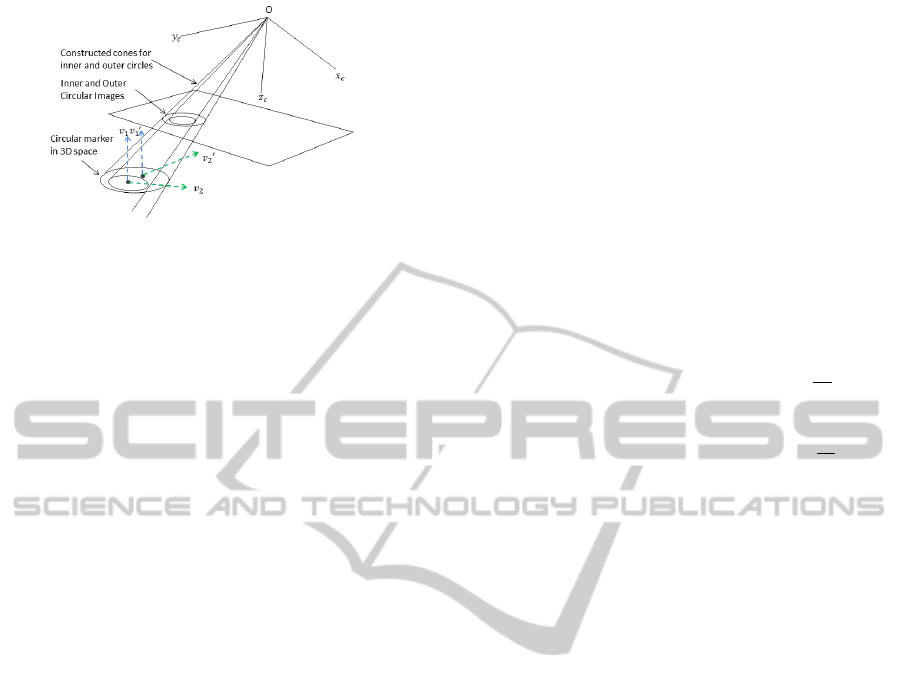
Figure 2: Schematic representation of a co-planar circle so-
lution method for duality problem.
projected ellipses e and e
0
can be obtained by calcu-
lating the eigenvalues and eigenvectors of the C and
C
0
, respectively. Finally, the areas A and A
0
are cal-
culated for both e and e
0
.
Step 3: Check whether A
o
= A and A
o
6= A
0
; if true,
then v is the true orientation of the circular feature.
If the orientation vector v has x and y compo-
nents equal to y and x components in v
0
(e.g. v =
g
1
g
2
g
3
T
and v
0
=
g
2
g
1
g
3
T
), then
the ellipse area cannot be used to differentiate be-
tween them. However, each ellipse will be projected
on different direction; therefore the eigenvectors of
the covariance matrix can be used to find the true pro-
jection, and the true orientation can be identified.
If the two orientation vectors v and v
0
have the
same components but different sign (e.g. v =
+g
1
g
2
g
3
T
and v
0
=
−g
1
g
2
g
3
T
),
then both vectors will result in the same covari-
ance matrix from (10), and neither the ellipse area
nor eigenvectors can be used to differentiate be-
tween them. In this case, the problem become ill-
conditioned, and we cannot identify the true orienta-
tion. The case arises from the fact that the 3D circle
may project into ellipse in 2D space in two different
directions.
4.2 Using a Co-planar Circle
The eccentricity of the circular image that has a sur-
face normal vector parallel to the principle axis of the
camera frame is equal to zero. This value change
when the circular feature moves with respect to the
camera. Our co-planar circle method uses two non-
coinciding circular features (inner and outer circles)
to identify their mutual true orientation. Since the in-
ner and outer circles have different centre points, the
change in the eccentricity values will lead to change
in the false orientation vector while the true one re-
mains constant. The concept illustrated in figure 2.
Let v
1
,v
2
are the orientation vectors for inner circular
image, and v
0
1
,v
0
2
are the estimated orientation vectors
for outer circular image. Therefore, the true orienta-
tion vector is the one that remains constant in both
circular features.
Conjecture: Co-planar circles have the same orien-
tation with respect to the camera frame, but differ-
ences in their eccentricity will result in differences
in their respective ”false” orientation vectors. The
inner and outer circles are co-planar, with different
centre points: their common orientation vector repre-
sents their true orientation (e.g. v
1
= v
0
1
and v
2
6= v
0
2
).
This method consists of two steps:
Step 1: Estimate the possible orientation vectors of
the inner and outer circular features (v
1
,v
2
, v
0
1
,v
0
2
), re-
spectively.
Step 2: Check if v
1
= v
0
1
and v
2
6= v
0
2
, then v
1
is the
true orientation of the circular feature.
If the diameter of the inner circle is I
d
=
O
d
2
, with
O
d
being the diameter of the outer circle. Then, the
method works reliably if the distance between the
centre points of inner and outer circles D ≥
O
d
5
. The
value of D has been experimentally established.
5 EXPERIMENTS
Three experiments were performed to validate the
proposed methods and oveall system of estimating the
3D orientation of the circular feature: (1) The first
experiment validates our first (reprojection) method
for resolving the duality problem and identify the true
orientation. Two groups of circle images were cap-
tured with known orientations. Each group contains
five circular features with the same orientation, but
different positions. Then, our reprojection method
used to identify the true orientation vector for each
circular feature. (2) The second experiment validates
our second (coplanar circle) method for resolving the
duality problem. Two groups of circular markers with
inner and outer circles were used to identify the true
orientations. A comparisons between our methods
with best state-of-art method are presented. (3) The
third experiment evaluates the accuracy of our frame-
work for estimating the 3D orientation of the circular
feature.
5.1 Setup
The experiment setup utilized the following hard-
ware imaging components for both experiments;
Canon PowerShot SX200 IS with resolution
4000x3000pixels and focal length: 5-60mm f/3.4-
5.3. Adjustable Angle Mounting Plate (API180)
which provides a full 180
◦
of movement with
18arcmin precision to holds the circular features (see
VISAPP2015-InternationalConferenceonComputerVisionTheoryandApplications
216
Figure 3: Circular images located on API180.
figure 3); and a 30 cm x 20 cm calibration board used
for camera calibration process. Intel Core i5-2450M
laptop, CPU@2.50GHz used to run the experiments.
5.2 Dataset
We have developed a new dataset for estimating 3D
orientation of the circular feature. The dataset in-
cludes two subsets: the first contain images for 136
circular objects with different diameters (0.7, 1.5 and
2 cm), and different positions and orientations with
respect to the camera. The second subset contains
50 images for circular markers with inner and outer
circles with different positions and orientations with
respect to the camera. The two subsets used to com-
pare our methods (reprojection and coplanar circle)
against current state-of-art methods. The dataset with
the setup description are available in (AlZoubi, 2014).
5.3 Verification of Reprojection Method
The method was verified by experiments using circu-
lar objects locates at distance 60cm from the camera.
Two groups of image circles with different orienta-
tions were acquired using the Canon camera. The di-
ameter of the circular objects in group 1 was 0.7 cm
and the diameter of the objects in groups 2 was 1.5
cm. Each group has five circular features located on
API180 at distances (20, 30, 40, 50 and 60cm) from
the centre of the image plane. Using API180, the
orientation vector and orientation angles of the cir-
cles’ planes were then estimated. These are referred
to as reference orientation vector and reference an-
gle (which represent the ground truth). The compu-
tational procedures of our framework were applied to
estimate the orientation vectors v and v
0
for each cir-
cular image. Following steps 1 through 3 in 4.1; the
projected ellipses e and e
0
from the vectors v and v
0
,
are computed and compared with the image ellipse e
o
in the image plane. The relative changes R
1
and R
2
in the ellipses areas A and A
0
comparing with A
o
were
calculated for the five circular images in each group
(where R
1
=
|A−A
o
|
A
o
and R
2
=
|A
0
−A
o
|
A
o
). The results of
Figure 4: (a) changes in R
1
and R
2
in group 1 of circular
images with rotation 75
◦
, 90
◦
,15
◦
around x, y, and z axes,
respectively; (b) changes in R
1
and R
2
in group 2 of circular
images with rotation 60
◦
, 90
◦
,30
◦
around x, y, and z axes,
respectively; (c) changes in S
1
and S
2
in group 3 of circular
images with rotation 75
◦
, 90
◦
,15
◦
around x, y, and z axes,
respectively; (d) changes in S
1
and S
2
in group 4 of circular
images with rotation 60
◦
, 90
◦
,30
◦
around x, y, and z axes,
respectively.
the two groups are shown in figures 4(a) and (b). Fig-
ure 4(a) shows the results for the five circular features
in group 1, these circular features were located at dif-
ferent positions with same orientation (75
◦
, 90
◦
,15
◦
around x, y, and z axes, respectively). The relative
changes between A and A
o
(which represent R
1
) are
very small and varies between the values 0.007% to
0.05%, while the relative changes between A
0
and A
o
(which represent R
2
) are varies between the values
9.5% to 23.8%. Thus, e is clearly the true projection
of ellipse in 2D space and match the image ellipse e
o
in the image plane. As can be noted from figures 4(a)
and (b), R
1
in the two groups are almost equal to zero,
while the change in R
2
varies significantly. Thus, e is
the true projection of ellipse in 2D space, and there-
fore, v is the true orientation for the circular feature
and v
0
is the false one in this case.
5.4 Verification of Co-planar Circle
Method
The co-planar circle method for solving orientation-
duality problem was verified by experiments using
a circular marker which consist inner and outer cir-
cles with different centre points. The inner and outer
circles have 1 cm and 2 cm diameters, respectively.
The distance between the centre points of the inner
and outer circles was 0.4 cm. Two groups of circular
markers with different orientations were acquired at
distance 60 cm from the camera. Each group con-
tains five markers located on the API180 and have
SolvingOrientationDualityfor3DCircularFeaturesusingMonocularVision
217

Table 1: Estimated orientation angles of the surface normal
of a set of circular images.
Angles α(
◦
) β(
◦
) γ(
◦
)
Reference Angle 75 90 15
Circle 1 76.16 88.57 13.91
Circle 2 76.44 89.55 12.99
Circle 3 76.17 88.17 12.97
Circle 4 76.77 89.75 13.42
Circle 5 74.93 89.89 16.26
Circle 6 74.78 89.94 15.54
Average 75.87 89.31 14.18
Average Deviation 0.87 0.69 0.82
the same orientation. The markers were located at
distances (20, 30, 40, 50 and 60 cm) from the cen-
tre of the image plane. The computational proce-
dures of our framework were applied to estimate ac-
curately the possible orientation vectors for inner and
outer circular features (v
1
,v
2
,v
0
1
and v
0
2
), respectively.
The API180 was used to define the reference ori-
entation vector and reference angles (which repre-
sent the ground truth). Following steps 1 and 2 in
4.2, the relative changes S
1
and S
2
in the parameters
v
1
,v
2
,v
0
1
and v
0
2
were calculated for the five circular
markers in each group (where S
1
= Angle(v
1
,v
0
1
) and
S
2
= Angle(v
2
,v
0
2
) ). Since the inner and outer circu-
lar feature are co-planar; the mutual orientation vector
between both of them is the true one, and therefore,
the angle between the true orientation vectors in both
circles must be equal to zero. The results for the two
groups are shown in figures 4(c) and (d). Figure 4(c)
shows the results for the five circular markers in group
3, these markers were located at different positions
with same orientation (75
◦
, 90
◦
,15
◦
around x, y, and
z axes, respectively). The angles between v
1
and v
0
1
(which represent S
1
) are:0.13
◦
, 0.14
◦
, 0.15
◦
. 0.14
◦
,
and 0.13
◦
for the five circular markers, respectively.
The angles between v
2
and v
0
2
(which represent S
2
)
are: 2.09
◦
,2.41
◦
,2.85
◦
,3.4
◦
, and 3.55
◦
for the five
circular markers, respectively. The values for S
1
are
very small, while the values in S
2
are higher. Thus,
S
1
is clearly the true solution, and therefore v
1
is the
true orientation vector. Similarly, group 4, as shown
in figure 4(d), has values of S
1
are almost equal to
zero, while the changes in S
2
varies significantly.
Comparison with the Existing Method. The
dataset described in section 5.2 was used to compare
the performance of our methods (reprojection and co-
planar circle) against the co-planar point method pro-
posed in (He and Benhabib, 1998). The dataset is
challenging due to the different objects diameters,
the objects loacted in different positions and orienta-
tions with respect to the camera, and the existence of
noise. Using API180, the orientation angles of the
circles were estimated and used as a ground truth.
The three methods were applied to the whole dataset.
The method (He and Benhabib, 1998) fails in 54% of
cases due to (1) identify the false orientation as true in
5% of the dataset, (2) the method was not able to dif-
ferentiate between the co-planar point and the noise
points in 19%, and (3) the method fails in 30% of the
dataset because the objects do not move between con-
secutive frames. In contrast, the reprojection method
and the co-planar circle method were able to identify
the true orientation of the circular objects in all cases,
even with the existence of noise or in the case where
the object stays in same location for two or more con-
secutive frames.
5.5 Evaluating Orientation Accuracy
The accuracy of our framework for estimating the ori-
entation of circular objects was tested on a group of
six co-planar circular images. The diameter of each
circular object was 0.7 cm and they were located at
distance 60 cm from the camera. Figure 3 shows a
sample of an image circles (tags) located on API180.
The computation procedures of our framework (in-
cluding the reprojection method) were applied to esti-
mate the 3D orientation for each circular feature. Us-
ing API180, the orientation angles of the circles plane
is then estimated. These are referred to as the ”Refer-
ence Angle” in Table 1, which shows the results of the
estimated orientation for each circular feature. The
six circles have the same orientation, since they are
co-planar. We have defined the average deviation of
the orientation as the absolute value of the difference
between the reference angle and the average angle,
measured as (0.87
◦
, 0.69
◦
, 0.82
◦
) rotation around x,
y and z axes, respectively. Note: α, β, and γ are the
angles that the surface normal of a circle makes with
the x, y, and z axes of the camera frame.
6 CONCLUSION
Two novel methods for solving the orientation-duality
problem have been proposed. The first compares fea-
tures from the 2D projects of both solutions with the
ellipse image in the image plane. This method solves,
and for the first time, the orientation duality problem
using a single 2D image without requiring additional
geometrical and texture features, nor an estimate of
the 3D position. The method has been tested on
circular objects with different orientations, positions
and different objects sizes. The experimental results
showed that the method is robust and perform better
than existing methods. One ill-conditioned case has
VISAPP2015-InternationalConferenceonComputerVisionTheoryandApplications
218

been identified; however, it can be detected and elim-
inated during run-time by acquiring another image of
the moving object. The second method relies on using
two non-coinciding co-planar circles, to identify their
mutual true orientation. This method does not require
multiple images nor a position estimate. The method
could be very useful for recognition of moving ob-
jects with circular markers as target to be tracked. The
method has been tested on circular objects with differ-
ent orientations, positions and object sizes. The ex-
perimental results showed that the method can iden-
tify the true orientation effectively and perform better
than existing methods. Our framework showed only
a small error for estimating the orientation of circular
feature (less than 1
◦
). The proposed methods are ef-
fective and solve the orientation-duality problem for
both static and object in motion, and it can be used to
identify the actual orientation of the circular objects in
real applications. Our system could be applicable for
tracking pre-marked animals (such as fish), and it has
applications in machine vision (e.g. tracking mobile
robot using circular marker), and autonomous takeoff
and landing of a Micro Aerial Vehicle. It could also
used to estimate eye gaze using a single 2D image.
REFERENCES
AlZoubi, A. (2014). 3dfishtrack: www.3dfishtrack.com.
Canny, J. (1986). A computational approach to edge detec-
tion. Pattern Analysis and Machine Intelligence, IEEE
Transactions on, (6):679–698.
Chen, Q., Wu, H., and Wada, T. (2004). Camera calibra-
tion with two arbitrary coplanar circles. In Computer
Vision-ECCV 2004, pages 521–532. Springer.
Fischler, M. A. and Bolles, R. C. (1981). Random sample
consensus: a paradigm for model fitting with appli-
cations to image analysis and automated cartography.
Communications of the ACM, 24(6):381–395.
Fitzgibbon, A., Pilu, M., and Fisher, R. B. (1999). Di-
rect least square fitting of ellipses. Pattern Analy-
sis and Machine Intelligence, IEEE Transactions on,
21(5):476–480.
He, D. and Benhabib, B. (1998). Solving the orientation-
duality problem for a circular feature in motion. Sys-
tems, Man and Cybernetics, Part A: Systems and Hu-
mans, IEEE Transactions on, 28(4):506–515.
Heikkila, J. and Silv
´
en, O. (1997). A four-step camera cal-
ibration procedure with implicit image correction. In
Computer Vision and Pattern Recognition, 1997. Pro-
ceedings., 1997 IEEE Computer Society Conference
on, pages 1106–1112. IEEE.
KaewTraKulPong, P. and Bowden, R. (2002). An im-
proved adaptive background mixture model for real-
time tracking with shadow detection. In Video-Based
Surveillance Systems, pages 135–144. Springer.
Linnainmaa, S., Harwood, D., and Davis, L. S. (1988). Pose
determination of a three-dimensional object using tri-
angle pairs. Pattern Analysis and Machine Intelli-
gence, IEEE Transactions on, 10(5):634–647.
Lowe, D. G. (1984). Perceptual organization and visual
recognition. Technical report, DTIC Document.
Safaee-Rad, R., Tchoukanov, I., Smith, K. C., and Ben-
habib, B. (1992). Three-dimensional location estima-
tion of circular features for machine vision. Robotics
and Automation, IEEE Transactions on, 8(5):624–
640.
Shiu, Y. C. and Ahmad, S. (1989). 3d location of circu-
lar and spherical features by monocular model-based
vision. In Systems, Man and Cybernetics, 1989. Con-
ference Proceedings., IEEE International Conference
on, pages 576–581. IEEE.
Wang, J., Sung, E., and Venkateswarlu, R. (2003). Eye gaze
estimation from a single image of one eye. In Com-
puter Vision, 2003. Proceedings. Ninth IEEE Interna-
tional Conference on, pages 136–143. IEEE.
Xu, W., Xue, Q., Liu, H., Du, X., and Liang, B. (2012). A
pose measurement method of a non-cooperative geo
spacecraft based on stereo vision. In Control Automa-
tion Robotics & Vision (ICARCV), 2012 12th Interna-
tional Conference on, pages 966–971. IEEE.
Yoon, Y., DeSouza, G. N., and Kak, A. C. (2003). Real-
time tracking and pose estimation for industrial ob-
jects using geometric features. In Robotics and Au-
tomation, 2003. Proceedings. ICRA’03. IEEE Inter-
national Conference on, volume 3, pages 3473–3478.
IEEE.
Young, R. A. (1987). Locating industrial parts with subpixel
accuracies. In Cambridge Symposium Intelligent
Robotics Systems, pages 2–9. International Society for
Optics and Photonics.
SolvingOrientationDualityfor3DCircularFeaturesusingMonocularVision
219
