
BarvEye
Bifocal Active Gaze Control for Autonomous Driving
Ernst D. Dickmanns
Technology of Autonomous Systems, University of the Bundeswehr, Munich, Germany
Department of Aero-Space Technology (LRT), Neubiberg, Germany
Keywords: Vision Systems (Automotive), Autonomous Driving of Road Vehicles.
Abstract: With the capability of autonomous driving for road vehicles coming closer to market introduction a critical
consideration is given to the design parameters of the vision systems actually investigated. They are chosen
for relatively simple applications on smooth surfaces. In the paper, this is contrasted with more demanding
tasks human drivers will expect to be handled by autonomous systems in the longer run. Visual ranges of
more than 200 m and simultaneous fields of view of at least 100° seem to be minimal requirements; potential
viewing angles of more than 200° are desirable at road crossings and at traffic circles. Like in human vision,
regions of high resolution may be kept small if corresponding gaze control is available. Highly dynamic active
gaze control would also allow suppression of angular perturbations during braking or driving on rough ground.
A ‘Bifocal active road vehicle Eye’ (BarvEye) is discussed as an efficient compromise for achieving these
capabilities. For approaching human levels of performance, larger knowledge bases on separate levels for a)
image features, b) objects / subjects, and c) situations in application domains have to be developed in
connection with the capability of learning on all levels.
1 INTRODUCTION
In the year 2013 several car manufacturing companies
and suppliers around the globe have announced that
cars with the capability of autonomous driving will be
on the market by 2020. Research vehicles
demonstrating increasing numbers of the set of
capabilities required for this purpose − based on
machine vision, various radar systems, and a number
of laser range finding systems − have been presented
over the last 30 years. A brief review will be given in
the next section.
Almost all of the systems considered rely on
sensors mounted fix to the vehicle body; they have at
most one rotational degree of freedom (dof). The
range of optical devices like video cameras and laser
range finders is limited to 60 ÷ 100 m, usually. On the
contrary, biological vertebrate vision systems (like
our own) have eyes with two highly dynamic
rotational dof in addition to being mounted on the
head with its own three rotational dof. This widely
proven design principle in biology should be
considered in the long run also for robotic systems
with the sense of vision, though the hardware base is
completely different. Carbon-based biological
systems (with relatively low switching times in the
millisecond range but many thousands of direct
connections to other neurons) have to be compared to
silicon-based technical systems with a few direct
cross connections only, but switching times several
orders of magnitude smaller and communication rates
several orders of magnitude higher.
If technical vision systems shall approach the
performance capabilities of the human vision system
eventually, it has been shown in (Dickmanns, 2007)
that an efficient approach might be to use a single-
axis yaw platform for mounting three small video
cameras as well as a very light single mirror on it with
one dof. This still seems to be the most cost effective
solution available today. However, the technology of
cameras has made so much progress meanwhile that
the design parameters for a ‘Bifocal active road
vehicle Eye’ (BarvEye) should be adapted. This is the
goal of the present paper.
Before this is started, in the next section a brief
view on the state of the art of machine perception for
road vehicles is given, covering the range of sensors
used and their performance limits. In section 3, the
environmental conditions to be handled in the long
run are reviewed. Based on these parameters, in
sections 4 and 5 the characteristics for a potential
“Bifocal active eye for road vehicles” are discussed.
428
Dickmanns E..
BarvEye - Bifocal Active Gaze Control for Autonomous Driving.
DOI: 10.5220/0005258904280436
In Proceedings of the 10th International Conference on Computer Vision Theory and Applications (VISAPP-2015), pages 428-436
ISBN: 978-989-758-091-8
Copyright
c
2015 SCITEPRESS (Science and Technology Publications, Lda.)

2 STATE OF DEVELOPMENT
The actual state can be characterized by decisions
made by car industry in the mid 1990’s and by
participants of the US ‘Defence Advanced Research
Project Agency’ “DARPA-Grand-Challenges”. The
approach selected by industry was to go for single
capabilities to be solved by vision, while others also
necessary had to be contributed either by the human
driver or by other means like range finding sensors,
GPS-localization and/or high-precision maps.
In the DARPA-Grand-Challenges of the first
decade of this century, road recognition by vision
played a minor role, since the vehicles were pulled
along the route by a virtual rope exploiting GPS-
position data and waypoints in a tight mesh.
Avoidance of obstacles above the ground (so called
‘positive obstacles’) was the major challenge. For this
purpose rotating laser range finders had been
developed by several institutions; the ‘Velodyne’-
sensor yielding 360°-depth images with 64 rows ten
times a second has been a successful result shaping
the development of vision for ground vehicles since.
In the automotive industries around the globe,
radar and laser-sensors have been preferred over
vision since data evaluation was simpler and could be
handled with much less computing power and
software development needed. Radar for obstacle
detection in road scenes had been investigated for
decades before the advent of lasers and real-time
image evaluation in the 1980’s. The all-weather
capability of radar is a big advantage, but it suffers
from relatively many false alarms due to multiple
reflections from surfaces of objects near the ground.
Two separate systems with specific wavelengths
seem becoming standard automotive sensors: 1.
Systems with frequencies in the band 76 − 77 GHz
(wavelength ~ 4 mm) for looking further ahead with
small aperture angles (up to 30°) and ranges up to ~
250 m, and 2. systems with ~ 24 GHz for peripheral
obstacle detection nearby. Both types yield relatively
precise range measurements, but poor angular
resolution (see ‘automotive radar’ in the web).
Laser Range Finders (LRF) work according to
similar principles of measuring runtime or phase, but
in the range of optical frequencies with much shorter
wave lengths; they are correspondingly more precise.
However, like vision they suffer from breakdown
under foggy or rainy weather conditions. At daytime
with sunshine, usable ranges are from 60 to 100 m for
moderately priced eye-safe systems. A variety of
concepts has been investigated: The simplest ones
have multiple lasers with fix angular orientation
and no revolving mirrors for changing the direction
of the outgoing laser beams; these systems suffer
from small fields of view and poor angular spacing
for resolving obstacles further away.
LRF with Constant Direction of the Generated
Laser Beams but with revolving mirrors in the paths
of the outgoing beams easily cover large fields of
view, but require precise measurements for good
angular resolution. They may be mounted within the
vehicle body; positioned at one of the vertical edges
they allow angular range coverage of over 140°.
The most successful LRF’s mentioned above,
yield depth images of the entire 360°-environment at
a rate of 10 Hz. They have rotating laser sources and
receivers. These sensors (e.g. Velodyne) have to be
mounted on top of the vehicle for achieving 360°
coverage. Forming an image for a definite point in
time over the full range requires quite a bit of
computational effort for correcting the time delays
during one revolution (up to 100 milliseconds). This
makes this type of sensor expensive. However, the
results demonstrated are impressive even though its
reliable range is limited (80 - 100 m); less expensive
versions with 32 (HDL-32) and 16 (VLP-16) parallel
laser beams are available respectively under
development (for details see ‘Velodyne’ in the web).
Video Sensors: With an increase in performance
of microprocessors by a factor of at least one million
since the early 1980’s (a factor of ten every 4 to 5
years), the evaluation of image sequences has
allowed substantial progress. Initially, mainly large
edge features with their adjacent average grey values
in black-and-white (320x240) image sequences have
been evaluated at a rate of 12.5 Hz. Combining this
with integrated spatiotemporal evaluation for scene
understanding exploiting feedback of prediction
errors [the so called 4-D approach (Dickmanns, 1987,
2007)]
resulted in a breakthrough in understanding
real-time image sequences from well-structured
environments like multi-lane highways.
Other visual features evaluated were corners,
blobs of similar image intensities or colors (color
components), so called image patches, and blobs of
similar textures. Both feature-based and neuronal
methods have been investigated since the 1980’s.
In the USA, the DARPA-project ‘Autonomous
Land Vehicle’ (ALV) since 1983 was one of three
application areas for a new generation of massively
parallel computer systems
(Roland and Shiman
2002). The EUREKA-project [PROgraMme for a
European Traffic of Highest Efficiency and
Unprecedented Safety]
‘PROMETHEUS’, running
from 1987 till 1994, had as one of its goals promoting
computer vision for autonomous guidance of road
vehicles.
BarvEye-BifocalActiveGazeControlforAutonomousDriving
429

While first publications were sparsely distributed on
conferences like IJCAI, SPIE-‘Mobile Robots’, and
CVPR, since 1992 there is a yearly ‘Inter-national
Symposium on Intelligent Vehicles’
[now: (IEEE-
IV’xy), xy = last 2 digits of the year] entirely devoted
to perception of roads and obstacles as well as
autonomous guidance of ground vehicles. In the
meantime, machine vision for guidance of vehicles is
spread over many conferences and journals. Reviews
may be found in (Tsugawa, Sadayuki, 1994; Bertozzi
et al., 2000; Dickmanns, 2002).
Capabilities demonstrated by computer vision
encompass road and lane recognition up to about 60
m (rarely 100 m) ahead, detection, tracking, and
estimation of own relative state to other objects
(stationary ones as well as moving ‘subjects’ like
other vehicles and humans), detection and mapping
of traffic signs and traffic lights, perception of
crossroads, their relative angular orientation and the
point of intersection with the own road and turning
off onto a crossroad to the right or left.
NASA Jet Propulsion Laboratory (Matthies,
1992), Sarnoff Research Laboratory (Burt et al.
1995), DLR Oberpfaffenhofen (Hirschmüller, 2011)
have pioneered different high-performance stereo
range estimation systems for ground vehicles.
Daimler is but one of several that have realized a
system with 10 to 12 bit pixel depth on an FPGA
board (Gehrig et al., 2009); sufficiently good results
for vehicle guidance are claimed up to ~ 60 m range.
At UniBw Munich driving on rural roads (including
dirt roads in the woods) has been developed using
vision components mounted on a gaze control
platform in conjunction with a Velodyne-LRF-sensor
(Bayerl, Wuensche, 2014).
The vision systems foreseen by industry for
application in the first generation planned for the car
market till 2020 all work with sensors mounted fix on
the body of the vehicle. Almost all of them rely on
additional range sensors for improving reliability.
The system Mobileye EyeQ2® offers the following
bundle of 9 functions: Lane Departure Warning,
Intelligent Headlight Control, Recognition of Traffic
Signs, vision-only Forward Collision Warning,
Headway Monitoring, City Collision Mitigation,
Pedestrian Protection, Traffic Jam Assist, Vision-
only Adaptive Cruise Control. The computing power
assembled is impressive: Two floating point, hyper-
thread 32bit RISC CPUs, five Vision Computing
Engines, three Vector Microcode Processors, plus
many I/O-channels (for details see ‘Mobileye EyeQ2’
in the web). All of this fits onto a single processor
board of size (65 x 33 x 10) mm weighing ~ 20 gram
and needing about 3 Watt electric power. This shows
the enormous progress made since the mid 1980’s
when a van was needed for carrying sensors, systems
for communication and control, and the computers.
All of this required a generator for electric power in
the range of several kW. − Mobile processor systems
predicted for the 2020’s continue this development
(e.g. NVIDIA TEGRA K1) with about 200 processors
and multiple video in- and output on a device of size
one inch square.
In conclusion, contrary to three decades ago,
sensor- and processor hardware does not seem to be a
limiting factor in the future for the design of small and
relatively inexpensive mobile vision systems. But
what is the proper system architecture? The next
section discusses general conditions to be handled.
3 ENVIRONMENTAL
CONDITIONS TO BE
HANDLED
It is assumed here that, contrary to the actual state of
system introduction, in the long run autonomous
driving should approach the capabilities of human
drivers both w.r.t. resolution and viewing ranges as
well as various perturbations to be handled.
3.1 Viewing Ranges
Driving on roads with fast bi-directional traffic,
relative speed of vehicles may be up to 250 km/h (~
70 m/s); this also is the recommended maximum
speed as upper limit on a German Autobahn on
sections without speed limit. At a speed of 180 km/h
(50 m/s), assuming half a second reaction time and an
average deceleration during braking of − 0.6 g (~ − 6
m/s²), a vehicle comes to full stop after a distance of
~ 240 m. At a speed of 130 km/h the same braking
conditions lead to a distance of ~ 127 m. Under poor
braking conditions (average − 0.3 g) the distance
needed is ~ 240 m for that speed. If at about 240 m
distance an object of 12 cm width in one dimension
(potentially harmful to the vehicle) should be covered
by at least 2 pixels for reliable detection, the
resolution required is 0,25 mrad/pixel.
Human eyes have a simultaneous horizontal field
of view of about 175° (~ 110° vertical), with coarse
resolution toward the periphery and very high
resolution in the ‘foveal’ center (~ 2° to 1° elliptic
aperture); in this region, the grating resolution is ~ 40
to 60 arc-sec, or about 0.2 to 0.3 mrad. This metric
(mrad) is a convenient measure for practical
applications; it gives the length covered by one pixel
VISAPP2015-InternationalConferenceonComputerVisionTheoryandApplications
430

normal to the optical axis at the distance of interest
(e.g.: width in dm at 100 m or in mm at 1 m)
. Detailed
discussions of, and references to all these aspects
treated in sections 3 and 4 here may be found in
(Dickmanns 2007, Chap.12).
With 2000 pixels per image line (row) the
simultaneous field of view would be only ~ 29° for a
resolution of 0,25 mrad/pixel. This clearly indicates
that a bifocal vision system is unavoidable for a
simultaneous field of view of only half that of
humans. Practical experience with joint image
evaluation in bifocal vision at UniBw Munich has
shown that spacing-in-focal-lengths should not
exceed the ratio of 4 for easy transition between the
image streams. This means that for a potential field of
view similar to the human one, both, more than one
camera and more than one focal length as well as gaze
control in the horizontal plane are required. Since
useful human stereo vision (with a base of about 7 cm
between the eyes) does not extend to more than 10 to
15 m this also is not necessary for machine vision if
proper image interpretation with background
knowledge is used. When a human observer can see
the point where an object touches the ground, in
standard driving situations on a smooth surface the
distance to the object can be estimated sufficiently
well from the ground region visible in the image
below the point of contact of that object with the
ground. For machine vision this means that the image
row (taking the pitch angle into account) directly
codes distance. The range to objects further away may
be inferred with sufficient accuracy from the
appearance of the road and lanes taking both
horizontal and vertical curvature of the road into
regard. Considering safety margins for unknown road
surface- and tire parameters, range accuracies of 5 to
10% seem reasonable for most practical purposes.
The large effort observable in actual developments to
extend visual stereo to 50 m and more does not seem
to be necessary once the proper knowledge base that
human drivers exploit is also implemented in machine
vision. Knowledge on the level of understanding
dynamic situations including the behavioral
capabilities of all essential subjects has to be
available.
At intersections with crossroads or traffic circles
a simultaneous field of view of 100° to 120° seems
reasonable for covering most of both the own road
and the crossroad simultaneously. Depending on the
task, the forward part of the left or right hemisphere
may be of interest. Instead of installing separate
sensor sets for each hemisphere on the vehicle, a
sufficiently large angular range in azimuth for gaze
control of a single device seems preferable. If good
resolution further away is requested at cross roads, the
pan angle of the platform should approach ± 90°. One
version of the resulting ‘eye for road vehicles’ will be
discussed in section 4.
3.2 Environmental Perturbations
Beside the lighting conditions changing over many
orders of magnitude, also the weather conditions with
respect to precipitation in form of rain, hail or snow
pose serious challenges to optical sensors. A large
effort has gone into developing video sensors with
dynamic ranges of up to 100 or even 120 dB.
Sensitivity of the sensor elements and control of
image integration time have led to video cameras
beyond expectations when machine vision started in
the early 1980’s. Yet, the physical limits of visibility
in fog and rain or snow for optical sensors persist.
These weather conditions have to be recognized for
autonomous adaptation of system parameters.
Actual vision systems are designed for smooth
riding conditions with comfortable cars. Angular
perturbations in pitch, roll, and yaw are rather small,
usually. This allows mounting the (short range) vision
sensors directly onto the vehicle body. Harsh braking
maneuvers may lead to larger angles Ө of
perturbation in pitch. With an amplitude A
Ө
= 3° and
eigen-frequencies of the vehicle in pitch of about 1.5
Hz (or ω ~ 10 rad/s) the maximal rotational speed A
ω
= ω A
Ө
is ~ 0.5 rad/s or about 20 mrad per frame (40
ms). With resolution 0.25 mrad/pixel (see above) this
corresponds to 80 rows of pixels in the image.
A car of 1.5 m height at 240 m distance covers 25
rows in the tele-image; search range from frame to
frame has to be kept large, but motion blur will make
recognition rather difficult, if not impossible.
Therefore, applying the very simple inertial rate
feedback that is exploited in biological (vertebrate)
vision systems, the perturbation amplitudes can be
reduced by more than one order of magnitude (see
Figure 1); note that this does not mean the inclusion
of an inertial platform but simply a tiny chip on the
gaze platform itself. This simple electro-mechanical
device helps saving much computing power.
However, since intended gaze changes shall not
be counteracted, a control scheme has to be
implemented for interrupting the direct inertial
feedback if desired. − The same scheme may be
applied in yaw direction also; since perturbations are
much slower there, usually, the reduction in search
space may not be that important. However, gaze
control in pitch and yaw is essential for tracking
objects with the tele-camera for high resolution.
BarvEye-BifocalActiveGazeControlforAutonomousDriving
431
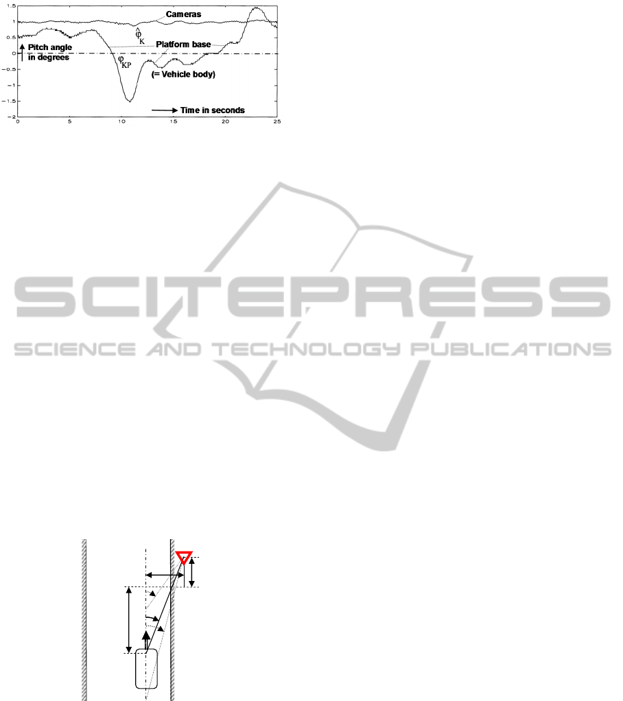
Figure 1: Gaze stabilization in pitch by negative feedback
of angular rate for the test vehicle VaMoRs (4-ton van)
during a braking maneuver.
4 DESIGN OF “VEHICLE-EYE”
In order to be able to satisfy the requirements
mentioned above and to read traffic signs at the side
of the road without motion blur early, tracking in both
pitch and yaw is required.
4.1 Saccadic Perception of a Traffic
Sign
Figure 2 shows the geometry of an experiment made
with the test vehicle VaMoRs for saccadic bifocal
detection, tracking, and recognition of a traffic sign
while passing at a speed of 50 km/h. The tele-camera
tracks the road at large look-ahead distances; it does
not have the task of detecting candidates for traffic
signs in this experiment. These have to be detected
and initially tracked in the wide-angle images. The
platform continues to track the curved road far ahead
with the tele-lens by gaze control.
Figure 2: Geometry for experimental vali-dation of
saccadic bi-focal sign recognition while passing (Hs is
normal to plane of the road).
While approaching the traffic sign, its projected
image travels to the side in the wide-angle image due
to the increasing bearing angle given as ψ(t) = arctan
(d/s) (see Figure 2 for a straight road). In the
experiment, d was 6 m and the vehicle moved at
constant speed V = 50 km/h. The graphs showing the
nominal aspect conditions of the traffic sign are given
in Figure 3; it shows the bearing angle to the sign in
degrees (left scale), the number of the image row
containing the center of the sign (right scale), and
time in seconds since detection of the sign (bottom).
The red boundary marking of the triangle was 8
cm wide; it was mapped onto two pixels at a distance
of about 28 m. The triangle was searched for in phase
1 (see arrow at top left) and detected at an angle of ~
15°. During phase 2 it was tracked over five frames
40 ms apart to learn its trajectory in the image (curve
1 in Figure 3, upper left). This curve shows
measurement results deviating from the nominal
trajectory expected. After the fifth frame, a saccade
was commanded to about 20°; this angle has been
reached in two video cycles (Figure 3, left side of
continuous curve 2). Now the traffic sign had to be
found again and tracked, designated as phase 3 (top).
After about half a second from first tracking, the sign
with 0.9 m length of its edges has been picked up
again, now in an almost centered position (curve 1,
lower center of Figure 3). It is mapped in the tele-
image also, where it covers many more pixels
sufficient for detailed analysis. The image is sent to a
specialist process for interpretation.
A saccade for returning to the standard viewing
direction was then commanded which was started half
a second after the first saccade (branch 2 in Figure 3,
right); about 0.6 s after initiating the first saccade
(lower scale), gaze direction was back to the initial
conditions. This shows that the design requirements
for the eye have been met. The video film
documenting this experiment demonstrates the speed
of the gaze maneuver with object acquisition, stable
mapping during fixation, and full motion blur during
saccades, when interpretation is interrupted.
The most demanding task for gaze control is
watching a traffic light above or to the side of the
road. Viewing angles may be large both in yaw and
in pitch, and perspective aspect conditions transform
the circular shape into an elliptical one.
4.2 Bifocal Active/Reactive Vehicle-Eye
All requirements discussed above have led to a
concept for a “Vehicle Eye” with fields of view as
shown in Figure 4. It represents a compromise
between mechanical complexity and perceptual
capabilities for understanding of road scenes. The
entire eye has one dof in yaw as shown in Figure 5.
At gaze direction 45° (not shown) both the road
ahead and a road crossing under 90° may be viewed
simultaneously. The system has a large redundantly
ψ(t)
s =
s
0
- V·∆t
d
H
s
Traffic sign
V
ס
Cameras
Vehicle
VISAPP2015-InternationalConferenceonComputerVisionTheoryandApplications
432
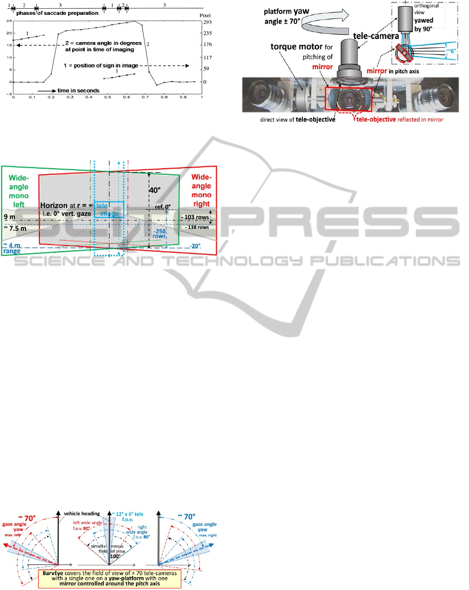
Figure 3: Position of traffic sign in wide angle image
(curves 1), and gaze direction of the yaw platform (curve 2)
for detecting, tracking, and high-resolution imaging of the
sign.
Figure 4: Visualization of the fields of view (f.o.v.) of the
three cameras of BarvEye on a 3-lane road: Two wide-angle
cameras (with 80° f.o.v., 20° oblique orientation of their
optical axes) and one tele-camera (~12° f.o.v.) in the region
of overlap, the vertical viewing direction of which can be
rotated by a mirror.
covered f.o.v. (central gray region in Figure 4); this
allows sufficiently good stereo interpretation in the
region nearby (10 to 15 m). The central stripe marked
by the blue dotted lines in Figure 4 allows
interpretation of trinocular stereo using data from the
tele-camera in addition (factor of 4 in resolution).
Figure 6 shows a visualization of the type of
“Vehicle Eye” proposed; an example realized by the
Institut fuer ‘Technik Autonomer Systeme, UniBw
Munich with own sets of parameters may be found
under [www.unibw.de/lrt8/forschung]. The tele-
camera is mounted vertically on the axis of the yaw-
platform to reduce moment of inertia and to allow
gaze control in pitch by the mirror (red) with 1 dof.
Figure 5: Ranges of yaw angles coverable by the single-dof
platform. The small f.o.v. of the tele-camera marked in blue
may be shifted vertically by a mirror with a dof in pitch (see
central part of Fig. 4 and 6).
Figure 6: Visualization of the design ideas of the ‘Bifocal
active road vehicle Eye’ BarvEye.
Beside inertial stabilization by angular rate
feedback as shown in Figure 1, two modes of
operation both for the yaw platform and for the mirror
drive have been conceived: 1. Smooth pursuit and 2.
Saccadic gaze shifts. The former one is used for
feature- or object tracking on demand of the
interpretation process exploiting prediction error
feedback. Saccades are initiated for centering the
tele-image on an object of special interest discovered
in the wide-angle images. Shifts to search regions
predicted from the mission plan and geographic maps
during approaches are other examples. Software
aspects and first experimental results are discussed in
(six papers at IV’00, Pellkofer et al., 2001;
Unterholzer, Wuensche, 2013).
5 CHARACTERISTICS OF 4-D
(DYNAMIC) VISION
The hyper-class of ‘subjects’ mentioned above
encompasses all objects capable of sensing and of
controlling at least part of their motion (their
movements) at will. For the many different types of
subjects to be found (all animals and robots)
subclasses have to be defined. The members of each
subclass may be viewed as specific individuals with a
variety of different body shapes, clothing and
behavioral properties; the capability of carrying
diverse loads contributes to an even wider range of
potential appearances. This is the reason for a need of
knowledge bases allowing all these distinctions in
visual perception that may affect proper own
behavior. This very demanding task requires
perceptual capabilities like the ones humans develop
over the first years of their life. For that purpose high
resolution in a wide range of gaze angles and their
control by the cognitive process are of special
importance.
BarvEye-BifocalActiveGazeControlforAutonomousDriving
433

5.1 Three Levels for Knowledge
Representation
To a large extent, knowledge about the world is
linked to classes of objects and subjects and to their
individual members. Beside geometric shape and
body articulation the classes of subjects and their
individuals are characterized by their capabilities of:
a) sensing, b) data processing and perception on the
mental level, c) decision making in situational
contexts, d) control actuation towards some goal.
As has been shown in (Niebles et al., 2010), more
reliable visual perceptions and higher discrimination
rates in complex scenes can be achieved by using
bottom-up models (from features to objects) and top
down models (scenes with objects) in parallel. The
approach described is well suited for initiating
tracking of individual members. To understand what
they are doing, it is necessary to have knowledge
about maneuvers performed and about the context
these are applied in. This means that three levels
should be used in parallel:
1. The visual feature level with links to real-world
moving 3-D objects / subjects;
2. The object / subject level with features and their
distribution on the 3-D surface; body shape and
articulation, typical movements of limbs, head /
neck and the body as part of maneuver elements
for locomotion or other goals; typical goals of
subjects in given situations.
3. The task domain on the situation level
containing typical environmental conditions
(geometry, lighting, weather) and types of object-
/ subject- classes to be encountered.
One basic task of cognitive subjects is to come up
with good decisions for their own behavior, given the
environmental conditions perceived. Thus, since
deeper understanding of movements depends on the
task domain and the situation, on the one side, and
since visual recognition of subjects depends on sets
of features and typical movements, on the other side,
the whole range from features of objects / subjects to
situations for subjects has to be considered in
parallel if human-like performance levels are the
(long-term) goal.
5.2 Shift in Emphasis for 4-D Vision
Instead of trying to exploit image data evaluation to
the utmost, as can be observed nowadays, it seems
more efficient to dare early jumps to object- / subject
hypotheses like in human perception and to exploit
rich knowledge bases on all three levels of perception
in parallel (visual features, real-world objects /
subjects, and situations in task domains).
Additional features derived from object-/ subject
hypotheses may be used during tracking phases in a
feedback mode of prediction-errors using recursive
estimation methods. Typical examples are to look for
wheels and tires or for groups of head- and backlights
relative to the position of vehicle bodies.
The additional degrees of freedom of subjects
require that for scene understanding ‘objects proper’
and ‘subjects’ have to be treated differently. While for
‘objects proper’ knowledge about laws of motion is
sufficient (e.g. a stone or ball on its trajectory in the
air), for subjects the self-decided variation of
movements is an additional degree of complexity for
adequate perception / understanding of maneuvers.
Frequently observed typical motion processes of
other objects or subjects form part of the knowledge
base for understanding of situations. Thus, typical
sequences of movements for the performance of
maneuvers have to be part of the knowledge base of
both agent and observer. In biological systems these
maneuvers are learned by repeated observation or by
own exercises from early-on during lifetime.
It is not the trajectory of the body and the limbs
that are learned but the time history of the control
output leading to these trajectories. This procedure is
a much more efficient encoding of the maneuver for
application since it concentrates on those variables
that are the only ones to be changed directly. Guiding
a road vehicle for a lane change thus does not require
a trajectory to be stored (with about half a dozen state
variables over its duration in time) but just the
piecewise constant time history of the one control
variable “steer angle rate” to be applied. So it makes
sense watching the angle of the front wheel relative
to the fender of a truck or a car just ahead in the
neighboring lane for proving the assumption that the
vehicle starts changing lane.
5.3 Situations in Task Domains
A ‘situation’ is defined as the complete collection of
all conditions relevant for decision making for a
subject. It encompasses all relevant environmental
conditions in the task domain. In an outdoor task:
Weather conditions, lighting- as well as visibility
conditions, surface conditions for ground vehicles,
local geometrical structure and buildings / objects /
subjects around. Also both the timing conditions and
the own health state are important.
All potential situations constitute such a
tremendous volume that subdivision into specific task
domains is mandatory. In human society, this is the
VISAPP2015-InternationalConferenceonComputerVisionTheoryandApplications
434

reason for the many existing professions. The basic
structure for handling different task domains may be
the same to a large extent. However, environments,
objects and subjects likely to be encountered as well
as typical behaviors of subjects may vary widely.
Within each task domain there are characteristic
maneuvers to be expected; therefore, driving on
highways, on city roads, on the country side or in the
woods requires different types of attention control
and subjects likely to be detected.
Learning which ones of these subjects with which
parameter sets are to be expected in which situations
is what constitutes “experience in the field”. This
experience allows recognizing snapshots as part of a
process; on this basis expectations can be derived that
allow a) focusing attention in feature extraction on
special events (like occlusion or uncovering of
features in certain regions of future images) or b)
increased resolution in some region of the real world
by gaze control for a bifocal system.
Crucial situation-dependent decisions have to be
made for transitions between mission phases where
switching between behavioral capabilities for the
maneuver is required. That is why representation of
specific knowledge of “maneuvers” is important.
6 CONCLUSIONS
In view of the supposition that human drivers will
expect from ‘autonomous driving’ at least coming
close to their performance levels in the long run, the
discrepancies between systems intended for first
introduction until 2020 and the features needed in the
future for this purpose have been discussed. A
proposal for a “Bifocal active road vehicle Eye” that
seems to be an efficient compromise between
mechanical complexity and perceptual performance
achievable has been reviewed and improved.
‘BarvEye’ needs just one tele-camera instead of more
than seventy mounted fix on the vehicle body to cover
the same high-resolution field of view. With respect
to hardware components needed, there is no
insurmountable barrier any more for volume or price
of such a system, as compared to the beginnings. The
software development in a unified design for detailed
perception of individuals with their specific habits
and limits continues to be a demanding challenge
probably needing decades to be solved. Learning
capabilities on all three levels of knowledge (visual
features, objects / subjects, and situations in task
domains) require advanced vision systems as
compared to those used in the actual introductory
phase.
REFERENCES
Bayerl S.F.X., Wuensche H.-J., 2014. Detection and
Tracking of Rural Crossroads Combining Vision and
LiDAR Measurements. In Proc. IEEE Int'l Conf. on
Intelligent Transportation Systems, 2014.
Bertozzi M., Broggi A, Fascioli A., 2000. Vision-based
intelligent vehicles: State of the art and perspectives.
Robotics and Autonomous Systems 32, pp 1–16.
Burt P., Wixson L., Salgian G., 1995. Electronically
directed “focal” stereo. Proc., Fifth Internat. Conf. on
Computer Vision, pp 94–101.
Dickmanns E.D, 1987: 4-D-Dynamic Scene Analysis with
Integral Spatio-Temporal Models. In: Bolles RC, Roth
B. 1988. Robotics Research, MIT Press, Cambridge.
Dickmanns E.D., Graefe V., 1988. a) Dynamic monocular
machine vision. Machine Vision and Applications,
Springer International, Vol. 1, pp 223-240. b)
Applications of dynamic monocular machine vision.
(ibid), pp 241–261.
Dickmanns E.D., 2007. Dynamic Vision for Perception and
Control of Motion. Springer-Verlag, (474 pp).
Gehrig S., Eberli F., Meyer T., 2009. A Real-time Low-
Power Stereo Vision Engine Using Semi-Global
Matching on an automotive compliant FPGA. ICVS.
Hirschmueller H., 2011 (Sept.). Semi-Global Matching -
Motivation, Developments and Applications. Photo-
grammetric Week, Stuttgart, Germany, pp. 173-184.
IJVAS-1, 2002. Vision for ground vehicles: history and
prospects. Int. Journal of Vehicle Autonomous Systems
(IJVAS), Vol.1 No.1, pp 1-44.
IV’00, 2000. Proc. Internat. Symp. on Intelligent Vehicles,
Dearborn (MI), with six contributions to Expectation-
based, Multi-focal, Saccadic (EMS-) vision:
1. Gregor R. et al.: EMS-Vision: A Perceptual System for
Autonomous Vehicles.
2. Gregor R., Dickmanns E.D.: EMS-Vision: Mission
Performance on Road Networks.
3. Hofmann U.; Rieder A., Dickmanns, E.D.: EMS-
Vision: Applic. to ‘Hybrid Adaptive Cruise Control’.
4. Luetzeler M., Dickmanns E.D.: EMS-Vision: Recog-
nition of Intersections on Unmarked Road Networks.
5. Pellkofer M., Dickmanns E.D.: EMS-Vision: Gaze
Control in Autonomous Vehicles.
6. Siedersberger K.-H., Dickmanns E.D.: EMS-Vision:
Enhanced Abilities for Locomotion.
Matthies L., 1992. Stereo vision for planetary rovers:
Stochastic modeling to near realtime
implementation. IJCV, vol. 8.
Niebles J.C., Han B., Li Fei-Fei, 2010. Efficient Extraction
of Human Motion Volumes by Tracking. IEEE
Computer Vision and Pattern Recogn. (CVPR).
Pellkofer M., Luetzeler M., Dickmanns E.D., 2001.
Interaction of Perception and Gaze Control in
Autonomous Vehicles. Proc. SPIE: Intelligent Robots
and Computer Vision XX; Newton, USA, pp 1-12.
Roland A., Shiman P., 2002. Strategic Computing: DARPA
and the Quest for Machine Intelligence, 1983–1993.
MIT Press.
BarvEye-BifocalActiveGazeControlforAutonomousDriving
435

Tsugawa S., 1994. Vision-based vehicles in Japan: Machine
vision systems and driving control systems. IEEE
Trans. Industr. Electronics 41(4), pp. 398-405.
Unterholzner A., Wuensche H-J. 2013. Selective Attention
for Detection and Tracking of Road-Networks in
Autonomous Driving. IEEE Int. Symp. Intelligent
Vehicles (IV’13), Gold Coast, Australia.
VISAPP2015-InternationalConferenceonComputerVisionTheoryandApplications
436
