
Biomechanical Effects of the Geometry of Ball-and-Socket
Intervertebral Prosthesis on Lumbar Spine Using Finite Element
Method
Jisu Choi
1
, Dong Ah Shin
2
and Sohee Kim
1
1
Department of medical system engineering, Gwangju Institute of Science and Technology, Cheomdan-gwagiro,
Gwangju, South Korea
2
Department of Neurosurgery, Yonsei University College of Medicine, Seoul, South Korea
Keywords: Lumbar Artificial Disc, Total Disc Replacement, Finite Element Method (FEM).
Abstract: The purpose of this study was to analyze the biomechanical effects of three different types of ball-and-
socket geometry of a lumbar artificial disc using finite element method. A three dimensional linear finite
element (FE) model was developed, and the lumbar artificial disc was inserted at L3-L4 level. The height of
implant was fixed and location of implant was also center-fixed. Three different curvatures of ball-and-
socket geometry were modeled (radius of curvature: 50.5mm for C1, 26mm for C2, 18.17mm for C3). The
biomechanical effects including range of motion (ROM), stress of intervertebral disc, facet contact force
and stress on implant were compared among different geometries. As the radius of curvature decreased, the
result shows that ROM increased at the surgical level and the stress on implant decreased. The change in
stress within intervertebral disc was not significant. The facet contact force at surgical level was maximum
with C2 while C1 and C3 had similar facet contact force. We confirmed that the geometry of artificial disc
can cause remarkable biomechanical changes at surgical level.
1 INTRODUCTION
Total disc replacement (TDR) has been accepted as
a better treatment due to its various advantages over
spinal fusion methods in degenerative disc disease
(Mayer and Korge, 2002). TDR preserves disc
height and inter-segmental range of motion. In
addition, adjacent level effect is lower than
conventional fusion methods (Panjabi et al., 2007).
Although TDR has many advantages, complications
have been reported (Bertagnoli et al., 2006). The
system can cause facet arthrosis and excessive
motion at surgical level, and it also has potential to
generate subsidence of metallic endplate of the
implant. In order to understand the reasons for
complications, many of previous studies have used
finite element analysis (Rohlmann et al., 2005),
(Rundell et al., 2008). The surgical methods such as
preserving the annulus fibrous, positioning the
implant, and re-suturing the anterior longitudinal
ligament could affect the motion biomechanically. In
addition, the size of facet joint gap leads different
biomechanical changes such as facet contact force at
surgical level. Although various factors were
investigated, the effect of implant geometry has not
been analysed. In the present study, the artificial disc
is based on ball-and-socket type, but the curvature of
ball-and-socket can vary. Accordingly, we aim to
investigate the effect of the curvature of ball-and-
socket implant and compare the biomechanical
effects at the adjacent and surgical levels of lumbar
spine using finite element method (FEM).
2 METHODS
A three dimensional linear finite element model was
developed and validated based on the study by
Yamamoto et al. The surgical finite element model
was constructed based on this validated model. The
height and location of implant were fixed and only
the curvature of ball-and-socket geometry was
varied. Three surgical FE models with different
implant geometries were constructed and compared.
116
Choi J., Shin D. and Kim S..
Biomechanical Effects of the Geometry of Ball-and-Socket Intervertebral Prosthesis on Lumbar Spine Using Finite Element Method.
DOI: 10.5220/0005213001160120
In Proceedings of the International Conference on Bioinformatics Models, Methods and Algorithms (BIOINFORMATICS-2015), pages 116-120
ISBN: 978-989-758-070-3
Copyright
c
2015 SCITEPRESS (Science and Technology Publications, Lda.)
2.1 Finite Element Model
The computed tomographic scan data of a healthy
24-year-old male was taken and reconstructed to
three dimensional geometry using Mimics software
(Materialise Inc., Leuven, Belgium). The 3D
geometry was imported to Hypermesh software
(Altair Engineering, Inc., Troy, MI, USA) and
converted from surface to solid type. Then, it was
meshed with finite elements. The cortical bone was
obtained from cancellous bone’s surface and
cartilage endplate was extracted from the surface of
intervertebral disc. The final FE model has five
vertebras (L1-L5), four intervertebral discs, and
ligaments. The total number of nodes and elements
were 398,260 and 945,960, respectively.
2.2 Material Properties
The material properties of each component were
obtained from previous literatures (Table1). Nucleus
pulposus has nearly incompressible property.
Annulus fibrous ground was modeled to be linear
elastic, and annulus fibers were not modeled in this
study. Ligaments were modeled to be linear elastic,
in which only tension can occur.
Table 1: Material properties of the used FE model.
Components
Young’s
Modulus
(MPa)
Poisson’s
ration
Reference
Cortical bone 5000 0.3
Rohlmann et
al. 2006b
Cancellous bone 50 0.2
Rohlmann et
al. 2006a
Posterior bone 3500 0.25
Rohlmann et
al. 2005
Nucleus Pulposus 1 0.499
Chen et al
Goel et al
Annulus fibrous 2 0.45
Lavaste et al.
1992
Cartilage
endplate
24 0.4
Goel et
al.1995a
Ligaments
ALL
PLL
CL
ITL
ISL
SSL
20
20
32.9
58.7
11.6
15
0.45
Goel et al.
1995a
Metallic endplate 210000 0.3 Liau JJ
Polyethylene
inlay
(UHMWPE)
1016 0.46 Liau JJ
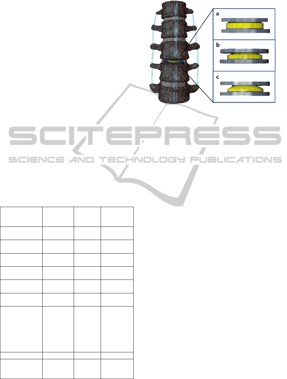
Figure 1: The surgical FE model with artificial disc at
L3/4 level and different curvatures of ball-and-socket
geometry. (C1: 50.5mm, C2: 26mm, C3: 18.17mm).
The FE model was exported to Abaqus software
(ABAQUS 6.13.; Hibbitt, Karlsson&Sorenson, Inc.,
Providence, RI, USA) after the material properties
were applied to each component of lumbar spine in
the model.
2.3 Surgical FE Model
The artificial disc was modeled to be 34.5mm,
27mm, and 2mm in width, length, and thickness,
respectively. The implant height was designed to be
8.7mm to fit the FE model. The implant was
modeled to have three different radii of curvature
(50.5mm for C1, 26mm for C2, 18.17mm for C3)
and inserted at L3-L4 level. Following the standard
surgical method, anterior longitudinal ligament and
Nucleus pulposus were removed and only lateral
Annulus fibrous was remained. The implant was
located at the center of vertebral body. The
coefficient of sliding contact between ball-and-
socket was 0.07 (Godest et al., 2002). The tie
interaction was applied to the endplates of implant
and vertebrae for complete fusion. The surgical FE
model is shown in Figure 1.
2.4 Boundary and Loading Condition
For validation of the intact FE model, we followed
the same protocol used in the study of Yamamoto et
al. The moment of 10 Nm was applied to the
superior surface of L1, and the inferior surface of L5
was fixed in all directions. The same boundary and
loading conditions were also applied to the surgical
models.
BiomechanicalEffectsoftheGeometryofBall-and-SocketIntervertebralProsthesisonLumbarSpineUsingFiniteElement
Method
117
3 RESULTS
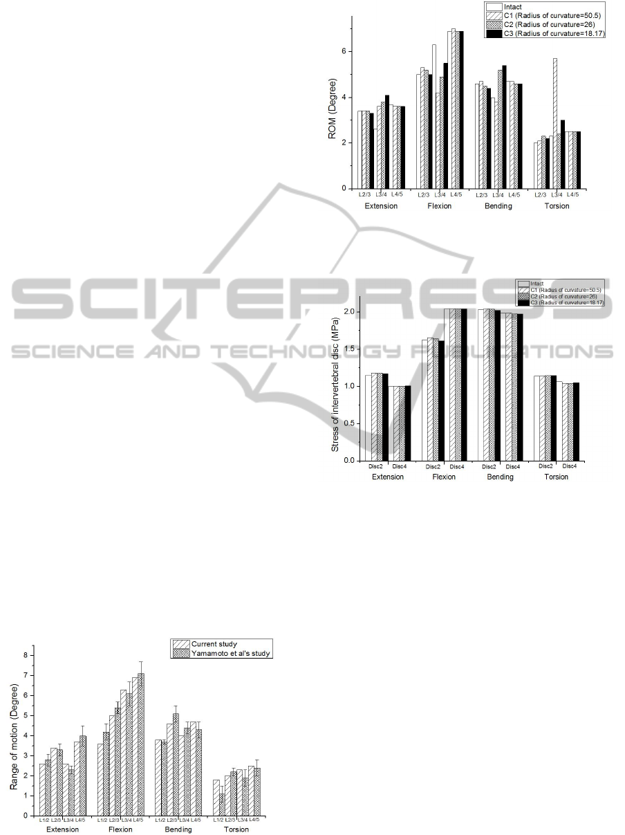
3.1 Model Validation
To validate the FE model, the range of motion of FE
model was compared with the results of the study by
Yamamoto et al (Yamamoto et al., 1989). The
results were within ±1 standard deviation of the
average of Yamamoto et al’s study in all motion
(Figure 2).
3.2 Range of Motion
There was no significant difference among all
groups at the adjacent level (L2/3, L4/5). However,
at surgical level, the ROM in C1, C2 and C3 models
was changed by +38.5%, +46.2%, and +57.7% in
extension, -33.3%, -22.2%, and -12.7% in flexion, -
5%, +30%, and +35% in bending, +191%, +4.3%,
and +30.4% in torsion, respectively compared to the
intact model. The results are shown in Figure 3.
3.3 The Stress of Intervertebral Disc
The stress of intervertebral disc at adjacent level
(L2/3, L4/5) was within +2.4% of that of the intact
model (Figure 4).
3.4 The Facet Contact Force
The facet contact force at the adjacent level (L4/5)
was not significantly changed. At the surgical level,
the facet contact force in C1, C2 and C3 models was
changed by -4.2%, +5.9%, and -19% in extension,
+81.9%, +172.3%, and +76.9% in lateral bending,
+116.2%, +140.5%, and +107.9% in axial torsion,
respectively compared to the intact model. The facet
contact force was maximum in C2, and minimum in
C3 (Figure 5).
Figure 2: Comparison of range of motion between current
study and Yamamoto et al’s study.
Figure 3: The range of motion with the different
curvatures of implant in extension, flexion, bending and
torsion at adjacent and surgical level.
Figure 4: The stress of intervertebral disc with the
different curvatures of implant in extension, flexion,
bending and torsion at adjacent level.
3.5 The Stress on Implant
The stress on implant decreased with the higher
degree of curvature in extension, flexion, and lateral
bending. In axial torsion, intact and surgical models
had relatively similar level of the stress on implant
(Figure 6).
4 DISCUSSION
In this study, we investigated the biomechanical
changes according to different curvatures of ball-
and-socket implant. Other factors that may affect the
result, such as the surgical method, location and
height of implant were fixed and only the curvature
of ball- and-socket was varied.
BIOINFORMATICS2015-InternationalConferenceonBioinformaticsModels,MethodsandAlgorithms
118
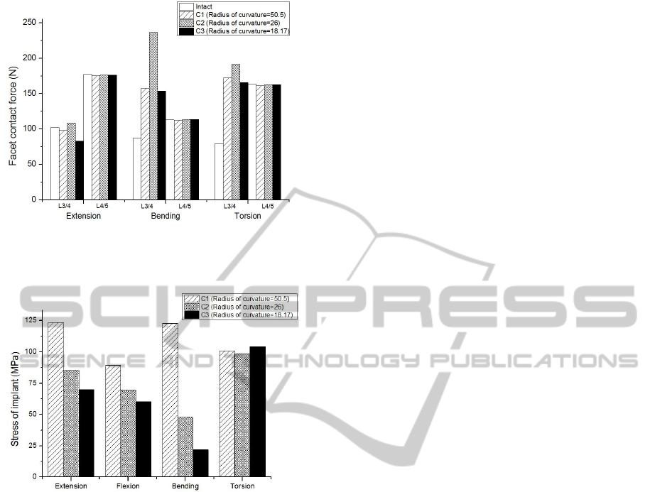
Figure 5: The facet contact force with the different
curvatures of implant in extension, bending and torsion at
L3/4 and L4/5level.
Figure 6: The stress on implant with the different
curvatures of implant in extension, flexion, bending and
torsion.
The range of motion, stress of intervertebral disc,
facet contact force, and stress on implant were
investigated with different curvatures.
The results show that the geometry of ball-and-
socket artificial disc caused remarkable
biomechanical changes at surgical level.
The general effects after inserting artificial disc
such as increase in ROM and facet contact force at
surgical level were similar to previous FE model
study (Chen et al., 2009). In this study, the range of
motion increased in extension, bending, and torsion
after TDR. However, the ROM decreased in flexion
after TDR. The reason for decreasing ROM in
flexion can be attributed to the location of implant.
A previous study related to TDR and intersegmental
rotation reported that even slightly anterior position
can cause significant ROM decrease in flexion
(Rundell et al., 2008). Accordingly, the location of
implant in this study could be slightly anterior rather
than center location. This issue, however, was not
critical because we focused on the geometry of
implant with fixed location. Also, the results were in
agreement with the previous study except for flexion.
In addition, the facet contact force increased after
inserting artificial disc as was reported by previous
studies (Kim et al., 2010).
The biomechanical effects according to the
geometry of implant at surgical level, such as the
ROM, facet contact force were significantly affected.
In addition, the stress on implant was also affected
by geometry of implant.
The entire ROM increased with decreasing
radius of curvature in extension, flexion, and lateral
bending. In axial torsion, ROM was maximum with
the largest radius of curvature. It was speculated that
the smaller radius of curvature enables the wider
range of motion, but the central point of rotation axis
misplaces in axial rotation.
The geometry of implant significantly affects the
facet contact force (FCF). The FCF was maximum
in C2, while C1 and C3 had similar values. It was
assumed that the FCF increased due to the
translation of vertebral body through the small
curvature and decreased with large curvature
because vertebral body rotates rather than translates.
The adjacent intervertebral disc stress was
similar among surgical models. The disc stress was
independent from geometry of implant.
Lastly, the implant stress tended to increase with
increasing radius of curvature in extension, flexion
and bending.
From these results, it turned out that the
translation or rotation of the artificial disc depends
on the curvature of ball-and-socket geometry. In the
case with smaller curvature, the artificial disc
translates through the curvature rather than rotates.
Therefore, the facet contact force increases and the
stress on implant also increases. Accordingly, the
facet arthrosis at surgical level and subsidence of
implant can be occurred. In addition, excessive
motion could be generated in axial torsion.
On the other hand, in the case with larger
curvature, the artificial disc rotates through the
curvature rather than translates. Therefore, the facet
contact force decreases and stress on implant also
decreases compared to the values with small
curvature. However, excessive motion can be
occurred in all motion.
Therefore, the curvature of implant should be
carefully considered to prevent undesired
complications in the future clinical application.
In this study, the follower load which represents the
intersegmental muscle force was not applied to the
FE model. Therefore, physiologic condition
BiomechanicalEffectsoftheGeometryofBall-and-SocketIntervertebralProsthesisonLumbarSpineUsingFiniteElement
Method
119

containing partial body weight and muscle force
should be included in future study.
5 CONCLUSIONS
In this study, we investigated that the geometry of
ball-and-socket implant can cause significant
biomechanical changes including ROM, facet
contact force at the surgical level. In addition, the
geometry of implant affects the stress on implant
itself. It is anticipated that this study can increase the
understanding of different biomechanical effects
with different curvature of implant at surgical level,
and contribute to designing improved ball-and-
socket artificial disc.
ACKNOWLEDGEMENTS
This work was supported by the grant from the
institute of Medical System Engineering (iMSE) at
GIST.
REFERENCES
Bertagnoli, R., Yue, J. J., Nanieva, R., Fenk-Mayer, A.,
Husted, D. S., Shah, R. V., Emerson, J. W., 2006. J.
Neurosurg. Spine 4, 85–90.
Chen, S.-H., Zhong, Z.-C., Chen, C.-S., Chen, W.-J.,
Hung, C., 2009. Med. Eng. Phys. 31, 244–253.
Godest, A. C., Beaugonin, M., Haug, E., Taylor, M.,
Gregson, P. J., 2002. J. Biomech. 35, 267–275.
Kim, K.-T., Lee, S.-H., Suk, K.-S., Lee, J.-H., Jeong, B.-
O., 2010. J. Korean Neurosurg. Soc. 47, 446–453.
Mayer, M. H., Korge, A., 2002. Eur. Spine J. 11, S85–
S91.
Panjabi, M., Henderson, G., Abjornson, C., Yue, J., 2007.
Spine 32, 1311–1319.
Rohlmann, A., Zander, T., Bergmann, G., 2005. Spine 30,
738–743.
Rundell, S. A., Auerbach, J. D., Balderston, R. A., Kurtz,
S. M., 2008. Spine 33, 2510–2517.
Yamamoto, I., Panjabi, M.M., Crisco, T., Oxland, T.,
1989. Spine 14, 1256–1260.
BIOINFORMATICS2015-InternationalConferenceonBioinformaticsModels,MethodsandAlgorithms
120
