
Improving Automatic Test Case Generation Process
with Knowledge Engineering in the Crystal Project
Stefano Marrone
1
, Roberto Nardone
2
, Antonio Maria Rinaldi
2
and Valeria Vittorini
2
1
Dipartimento di Matematica e Fisica, Seconda Universit
`
a di Napoli, Caserta, Italy
stefano.marrone@unina2.it
2
Dipartimento di Ingegneria Elettrica e Tecnologie dell’Informazione,
Universit
`
a di Napoli Federico II, DIETI, Napoli, Italy
{roberto.nardone, antoniomaria.rinaldi,
valeria.vittorini}@unina.it
Abstract. Recent research advances have brought to a growing interest from
both academic and industrial communities in the improvement of existing engi-
neering processes by means of model-driven techniques. This method is starting
to demonstrate its effectiveness by raising the level of abstraction and by improv-
ing the level of automation of traditional processes. One of these applications is
related to V&V processes and in particular to the generation of system level test
cases for critical systems. This chapter investigates the possibility to further im-
prove such process by exploiting synergies between model-driven techniques and
knowledge engineering ones. This work is developed in the context of Crystal, an
EU Artemis funded research project, and focuses on a specific part of its frame-
work. The proposed approaches are demonstrated by means of a case study in the
field of railway signalling system.
1 Introduction
Ontologies constitute formal models of some aspect of the world that may be used for
drawing interesting logical conclusions even for large models. Software models capture
relevant characteristics of a software artefact to be developed. Most often these software
models have no formal semantics, or the underlying (often graphical) software language
varies from case to case in a way that makes it hard if not impossible to fix its seman-
tics. In this context, ontology-based metamodels constitute a core means for exploiting
expressive ontology reasoning in the software modelling domain while remaining flex-
ible enough to accommodate varying needs of software modellers [1]. With this aim,
the four-layer modelling architecture provides the basis for formally defining software
modelling languages and some open challenges can be recognised: semantics of mod-
elling languages often is not defined explicitly but hidden in modelling tools; to fix a
specific formal semantics for metamodels, it should be defined precisely in the meta-
model specification; the syntactic correctness of models is often analysed implicitly
using procedural checks of the modelling tools; to make well-formedness constraints
more explicit, they should be defined precisely in the metamodel specification. Ontolo-
gies and the related languages to represent them can be used to improve the expressive
power of software metamodels.
Nardone R., Marrone S., M. Rinaldi A. and Vittorini V.
Improving Automatic Test Case Generation Process with Knowledge Engineering in the Crystal Project.
DOI: 10.5220/0006156500310049
In European Project Space on Computational Intelligence, Knowledge Discovery and Systems Engineering for Health and Sports (EPS Rome 2014), pages 31-49
ISBN: 978-989-758-154-0
Copyright
c
2014 by SCITEPRESS – Science and Technology Publications, Lda. All rights reserved
31

In the last two decades, ontological aspects of information have acquired a strate-
gic value. These aspects are intrinsically independent from information codification,
so the information itself may be isolated, recovered, organised and integrated with re-
spect to its content [2]. A formal definition of ontology is proposed in [3], according to
whom “an ontology is an explicit and formal specification of a shared conceptualisa-
tion; conceptualisation is referred to as an abstract model of specified reality in which
the component concepts are identified; explicit means that the type of concepts used
and the constraints on them are well defined; formal refers to the ontology property of
being “machine-readable”; shared is about the property of an ontology of capturing the
consensual knowledge, accepted to a group of person, not only to a single one.
A basic step in the knowledge engineering process is the use of “tools” to represent
knowledge, both for inferring and organising it. From this point of view, one of the most
important advances in the knowledge representation (KR) applications is derived from
proposing [4], studying [5–7] and developing [8–10] languages based on the specifica-
tion of objects (concepts) and the relationships among them. The main features of all
KR languages are the following:
(i) object-orientedness, for which all the information about a specific concept is stored
in the concept itself (in contrast, for example, to rule-based systems;
(ii) generalization/specialisation are basic aspects of the human cognition process [4],
the KR languages have mechanisms to cluster concepts into hierarchies where
higher-level concepts represent more general attributes than the lower-level ones,
which inherit the general concept attributes but are more specific, presenting addi-
tional features of their own;
(iii) reasoning is the capability to infer the existence of information not explicitly de-
clared by the existence of a given statement;
(iv) classification in which given an abstract description of a concept, there are mech-
anisms to determine whether a concept can have this description; this feature is a
special form of reasoning.
Object orientation and generalization/specialisation help human users in understanding
the represented knowledge; reasoning and classification guide an automatic system in
building a knowledge representation, as the system knows what it is going to represent.
Moreover, we argue that when a KR formalism is constrained in such a way that
its intended models are made explicit, it can be classified as belonging to the ontolog-
ical level [11] introduced in the distinctions proposed in [7], where KR languages are
classified according to the kinds of primitives offered to the user.
In recent years, several languages have been proposed to represent ontologies. These
languages have a different expressive power and, starting from some considerations
from previous authors’ works [12, 13], it is our opinion that OWL [14] is the best lan-
guage for the purpose of the proposed approach.
OWL 2, the web ontology language, is a W3C recommendation with a very compre-
hensive set of constructs for concept definitions and allow for specifying formal mod-
els of domains. Generally speaking, ontologies are conceptual models, that can be de-
scribed by OWL. Based on its underlying formal semantics and different services could
be provided. They vary between satisfiability checking at the model layer, checking the
32
EPS Rome 2014 2014 - European Project Space on Computational Intelligence, Knowledge Discovery and Systems Engineering for Health
and Sports
32

consistency of instances with regard to the model, or classifying instances (finding their
possible types) with regard to instance and type descriptions. Since ontology languages
are described by metamodels and allow for describing structural and behavioural mod-
els, they provide the capability to combine them with software modelling languages. In
our framework we want use ontologies to support the definition of software modelling
language semantics and provide the definition of syntactic constraints.
A second concern that is at the base of this Chapter is a growing need coming from
industrial settings to introduce advanced modelling approaches into existing develop-
ment processes. This need is raised not only by industries more prone to innovation in
ICT but also by the manufacture industries where the development processes are well
assessed and where managers are less prone to change them. Model-Driven Engineer-
ing (MDE) [15] is starting to be applied in this contexts; notwithstanding the absence of
universally accepted standard processes, it is still one of the most promising techniques
to improve productivity. By means of model-driven techniques both requirements elic-
itation and analysis, design space exploration and verification & validation phases of a
product/service life-cycle can be improved: this can be accomplished by processes built
upon the two pillars of the MDE:
(i) metamodelling, which allows the structure of a domain in terms of abstract and
concrete domain models with textual/graphical languages as well as by extending
existing languages (e.g., UML profiling mechanism);
(ii) model transformation, by means of which it is possible to automatically generate
artifacts that can code (as in Model Driven Software Development) as well as fur-
ther models (e.g., Petri Nets, Bayesian Networks, etc.).
From all the industrial sectors and the development phases that may be improved in
this way, this work is focused on verification processes in railway signalling systems. In
particular we focus on automated testing processes (at system level) as a way to improve
the quality/safety of the product and to reduce costs and time. Several research works
proposes improvements of this specific topic by means of model-driven approaches (a
great part of this work are framed into the Model-Driven Testing - MDT).
Due to the high number of common aspects between KR and MDE approaches, the
objective of this work is to explore the synergies between these two worlds on the spe-
cific problem of automated testing process. A mixed KR-MDE approach of the entire
system testing process is defined with enabling techniques as well as present issues.
This ongoing work is framed into the ARTEMIS Joint Undertaking project CRYSTAL
(CRitical sYSTem engineering AcceLeration) [16] that will be further described in the
next sections.
The Chapter is structured as follows: Section 2 presents the CRYSTAL project while
Section 3 focuses on the specific Use Case of this work. Section 4 describes the overall
approach of KR-MDE integration in the improvement of automated testing process and
Section 5 details an aspect of the entire process. Section 6 draws conclusions and future
developments.
33
Improving Automatic Test Case Generation Process with Knowledge Engineering in the Crystal Project
33
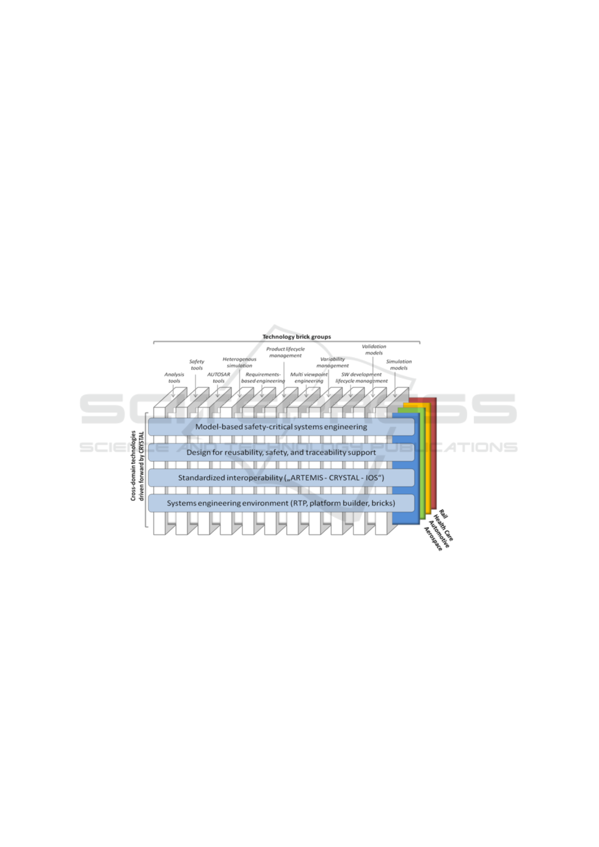
2 An overview of the Crystal Project
CRYSTAL takes up the challenge to establish and push forward an Interoperability
Specification (IOS) and a Reference Technology Platform (RTP) as a European stan-
dard for safety-critical systems. CRYSTAL is strongly industry-oriented and will pro-
vide ready-to-use integrated tool chains having a mature technology-readiness-level.
Figure 1 depicts this overview.
To achieve technical innovations (“technology bricks”), CRYSTAL adopts a user-
driven approach based on applying engineering methods to industrially relevant Use
Cases from the automotive, aerospace, rail and health-care sectors [17] and increases
the maturity of existing concepts developed in previous European and national projects
like CESAR [18], iFEST [19], MBAT [20]. Moreover several product life-cycle or
project management phases/concerns are used to group together similar research task
in the Crystal project. They are: analysis tools, safety tools, AUTOSAR tools, het-
erogeneous simulations, product life-cycle management, multi viewpoint engineering,
variability management, SW development life-cycle, validation models and simulation
models.
Fig. 1. The Crystal Overview (http://www.crystal-artemis.eu).
Four cross domain technologies cut the entire space of domains and of development
life-cycle phases which Crystal embraces: model-based safety critical system engineer-
ing, design for reusability and traceability support, standardised interoperability and
system engineering environments. As it is clear, model-driven engineering and knowl-
edge engineering are first class citizens in the vision of the Crystal project and hence,
finding ways in where these two pillars of the software engineering can express their
synergies, is a research task of a great value.
34
EPS Rome 2014 2014 - European Project Space on Computational Intelligence, Knowledge Discovery and Systems Engineering for Health
and Sports
34
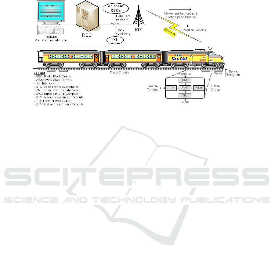
Fig. 2. ERTMS/ETCS Level 2.
The achievement of a good level of interoperability cannot leave aside the definition
of specific domain ontologies in such big cross-domain project. In fact, in Crystal, one
ontology for each domain are the output of specific work packages. The advantages of
these activities can be found in the definition of a common vocabulary in the specific
domain, in the simplification of communication thorough the different operators and in
the usage of a common glossary in the deliverables and artefacts of the project. Further-
more the application of ontology activities is at the basis of the definition of the IOS
which can take advantages from these domain ontologies operating in a cross-domain
manner.
3 The RBC Use Case within the Crystal Project
The focus of this work is in the rail domain, and specifically from the needs expressed by
Ansaldo STS (ASTS), an international transportation leader in the field of signalling and
integrated transport systems for passenger traffic (Railway/Mass Transit) and freight
operation. The industrial needs expressed by the ASTS’s Use Case are oriented to im-
prove the quality and the efficiency of existing Verification & Validation (V&V) pro-
cesses, with a specific focus on the validation of functional requirement with testing. In
fact, testing activities are time-consuming tasks whose efficiency is a primary issue in a
global competitive market and whose quality can not be decreased due to the adherence
to international standards.
3.1 The RBC Use Case
The ASTS’s Use Case is centred on the Radio Block Centre (RBC) system, a computer-
based system whose aim is to control the movements of the set of trains on the track
area under its supervision, in order to guarantee a safe inter-train distance according
to the ERTMS/ETCS specifications. ERTMS/ETCS (European Rail Traffic Manage-
ment System/European Train Control System) [21] is a standard for the interoperability
35
Improving Automatic Test Case Generation Process with Knowledge Engineering in the Crystal Project
35

of the European railway signalling systems ensuring both technological compatibility
among trans-European railway networks and integration of the new signalling system
with the existing national train interlocking systems. Each ERTMS/ETCS controlled
track is usually divided into several sub-tracks, each of them is supervised by a single
RBC in charge of concurrently and continuously controlling a number of connections
with trains. The main objective of the train control system is to timely transmit to each
train its up-to-date Movement Authority (MA) and the related speed profile. The MA
contains information about the distance the train may safely cover, depending on the
status of the forward track. RBC is also in charge of managing emergency situations if
the communication with one or more trains is compromised. Figure 2 gives an overview
of the ERTMS/ETCS lev 2 at a glance.
With a particular focus on the validation of the system against functional require-
ments, a great effort is spent on the generation, execution and analysis of system-level
functional test cases. Since these systems are classified as the most dependable in terms
of Safety Integrity Level (i.e., they are classified as SIL 4) and according to the applica-
ble international standards and norms (i.e., CENELEC EN50128 [22] and CENELEC
EN50126 [23]), these activities must be conducted by a proper “V&V team” which
shall be independent from the development team. This team must rely only on high-
level behavioural description of the system and on the set of system requirements that
the system have to satisfy; its objective, at system level, is the definition of test cases
able to functionally validate the overall system against its requirements.
An improvement of the actual V&V approach is hence required for these systems,
allowing the automatic execution of some activities. For these reasons our goal in the
CRYSTAL project is represented by the definition of a new methodology which must
be able to support the execution of these activities: on the basis of a system model is
used to drive the process by means of automatic tool. The main activities that have been
traditionally done manually are now supported by tools even if the interaction with a
V&V Engineer is present.
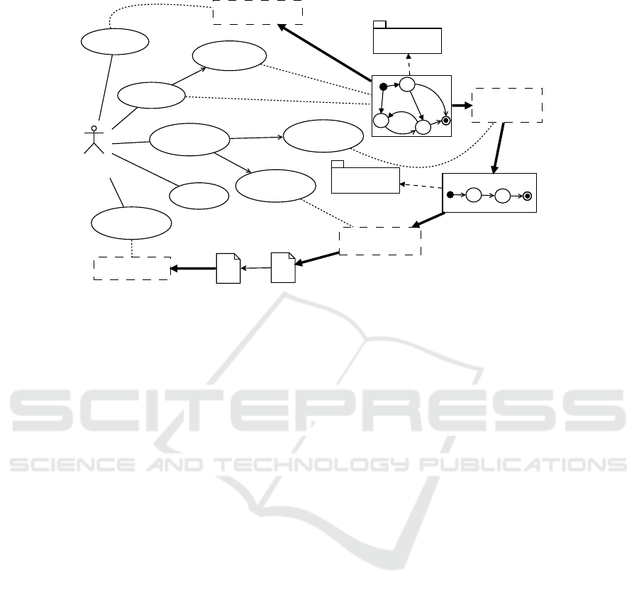
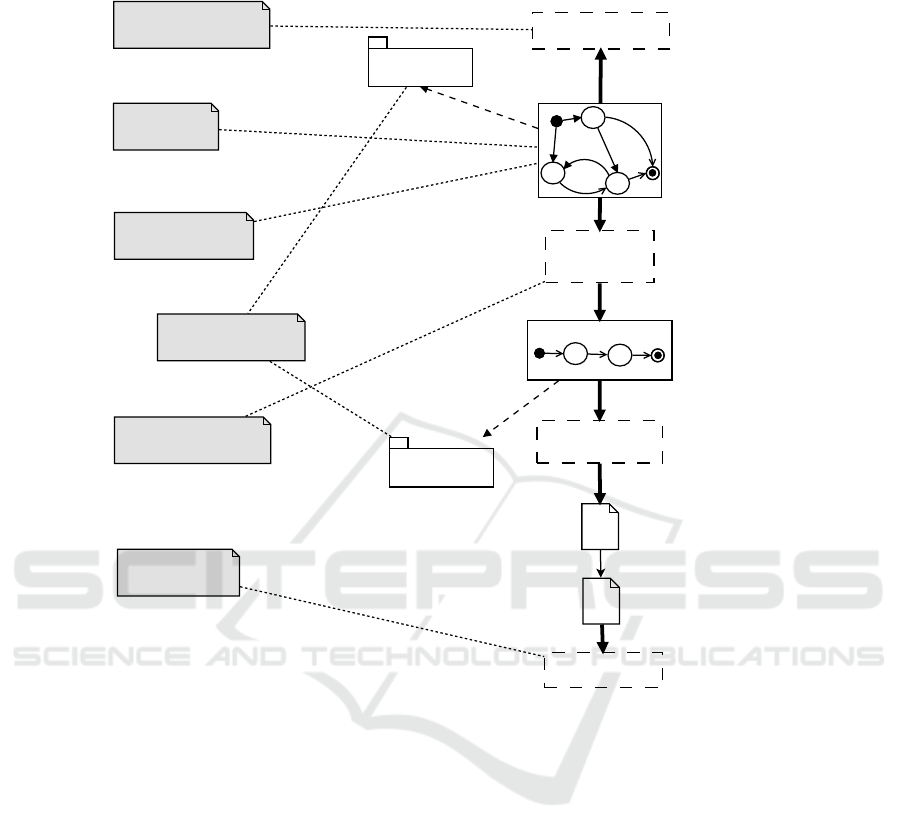
Figure 3 shows, by means of a diagram mixing UML Use Case elements and an
architectural schema, the interactions between user and system as well as the tool sup-
porting such functionalities. In the diagram, tick solid lines represent automatic flows,
solid thin lines activities that are executed outside this automated process while dotted
lines related use cases with automatic tools. A similar approach and supporting archi-
tecture has been defined in [24] but, in that paper, the approach is oriented in mixing
functional and non-functional properties. With respect to another previous work [25]
this description is enriched with more details and it constitutes an improvement.
The flow of activities can be described as follows. The V&V Engineer is in charge to
Model RBC functions in one System Model that is conformant to the Dynamical StaTe
Machine (DSTM) language. This language, considering both the needs of a strong for-
mal foundation and ease of use of the final user, it is defined according to principles
of MDE as a Domain Specific Modelling Language (DSML). Further discussion on
DSTM is in Subsection 3.2. Essentially, DSTM is an extension of state machines where
the behaviour of the system is represented by states and transitions. Furthermore, the
model is annotated with functional requirements (Model Functional Requirements):
up to date, requirements are mapped onto transitions.
36
EPS Rome 2014 2014 - European Project Space on Computational Intelligence, Knowledge Discovery and Systems Engineering for Health
and Sports
36
conforms to
DSTM
<<metamodel>>
System Model
Test Generator
TESQEL
<<metamodel>>
conforms to
Test Sequence Model
V&V
Engineer
<<include>>
<<include>>
<<include>>
DSTM Verifier
IOP Test Writer
Log Analyser
Test Script
Execution Log
Verify Model
Model RBC
Functional
Requirements
Abstract
Test Sequence
Concrete
Test Sequence
Generate
Test Sequence
Execute
Tests
Analyze
Execution Logs
Fig. 3. The RBC Use Case Automated Testing Process.
After the model is created, it should be verified in order to check if it conforms to all
the constraint of the language (Verify Model): this action is supported by the DSTM
Verifier tool. Up to date, this tool is essentially a compiler which takes different parts
of a DSTM model and verify the consistency of the model itself and its compliance to
all the constraints defined in the DSTM language. Different techniques may be used
to specify the model: while structural elements of the model itself are better created
trough a graphical concrete syntax, for variables and data-types, the best way still is
a textual old-style concrete syntax. Both traditional parsing techniques and advanced
model-driven manipulation and querying approaches are used.
Then, test-sequences can be automatically generated, with a minimum effort re-
quired to the V&V team (Generate Test Sequences): this activity can be parted into
a phase where “abstract” sequence are generated (Abstract Test Sequence) and one
where abstract test sequences are realised in a concrete scripting language and able to
be executed (Concrete Test Sequence).
The generation of abstract test sequences supported by the Test Generator tool that
works as follows: a test specifications is actually derived from the requirements and it
contains the features that a test sequence to generate must own (see for a fully descrip-
tion of this item [26, 27]). At the state, two test specifications are generated for each
requirement: a finite set of ‘positive’ test specifications (i.e., the situations in which the
transition must be performed), and one ‘negative’ test specification (i.e., the situation
in which the transition have not to be performed). Starting from these hypotheses, the
model and each test specification generate a Test Sequence Model which represents
one of the many concrete executions on the System Model which fulfils the test spec-
ification. This last artefact is conformant to the TEst SeQuEnce Language (TESQEL)
which is also built according to model driven principles. At the state, the Test Generator
is implemented by exploiting model checking techniques [28]: a DSTM model is hence
37
Improving Automatic Test Case Generation Process with Knowledge Engineering in the Crystal Project
37

translated into a Promela language while the negation of the test specification becomes
a CTL property to check. The counterexample is the sequence of execution steps on
the model which negates the property (i.e. which satisfies the test specification). This
notwithstanding, future developments can consider different approaches for the Test
Generator mechanism.
Generated test sequences must be executable and hence TESQEL conformant se-
quences are translated into an executable language by the IOP Test Writer which aim
is to translate the “model” of the test sequence into an interoperable language for the
execution of ERTMS/ETCS tests (the IOP language itself) (Test Script).
Once these scripts are executed, outside of this approach, Execution Logs are pro-
duced: these logs are analysed (Analyze Test Logs) in order to understand if some
anomalies are present. This phase is supported by the Log Analyser.
It is important to underline that the IOP Test Writer and the Log Analyzer are not in
charge of the research units of Seconda Universit
´
a di Napoli and of Universit
´
a di Napoli
Federico II. This notwithstanding in this chapter we discuss also on these tools about
the possibility to improve them. Such improvements could be done outside the context
of the CRYSTAL project.
3.2 The DSTM Language
DSTM extends Hierarchical State Machines [29] specifying an original semantics of
fork-and-join. This makes DSTM more powerful than the UML State Machines [30]
since it adds, between others, mechanisms for dynamic instantiation and recursive exe-
cution of machines. An excerpt of the DSTM metamodel is shown in Fig. 4, where the
Ecore diagram is depicted. This Ecore diagram represents the realisation of DSTM,
which formalisation have been introduced in [31], in the Eclipse Modeling Frame-
work [32]. The main class is Dynamic State Machine (DSTM), which represents the
entire specification model. A DSTM is composed of different Machines, Channels and
Variables and allows for the definition of own-defined Types. Channels and Variables
allow for communication between machines and with the external environment. A sin-
gle Machine is composed of Vertexes, Transitions and may have a set of Parameters.
The class Vertex is abstract since different kinds of vertexes (with different features
and constraints) may be present in a machine. The vertex kinds are similar to those con-
tained in the UML State Machine, but with a different semantics for the Fork and Join
concepts. A fork splits an incoming transition into more outgoing transitions; it allows
for instantiating one or more processes either synchronously or asynchronously with
the currently executing process. The asynchronous instantiation represents the instanti-
ation of machines without suspending the current executing process, which is enabled to
continue its evolution. On the contrary, a join merges outgoing transitions from concur-
rently executing processes: it synchronises their termination together with the current
executing process, if asynchronous instantiation have been performed, and/or allows
to force the termination when a process is able to perform a preemptive exiting tran-
sition. The classes Fork, Join and EnteringNode are inherited from the abstract class
PseudoNode which encompasses different types of transient vertexes in the machine.
The class Transition is specified by many attributes. It can specify its trigger, its ac-
tivation condition and a set of actions. These attributes are specified by a string that must
38
EPS Rome 2014 2014 - European Project Space on Computational Intelligence, Knowledge Discovery and Systems Engineering for Health
and Sports
38
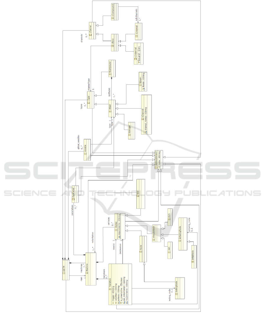
Fig. 4. DSTM4Rail metamodel [31].
39
Improving Automatic Test Case Generation Process with Knowledge Engineering in the Crystal Project
39

comply with a given syntax. Furthermore a transition can be preemptive, i.e. enabled
to kill concurrent executing processes, by setting to true the value of the is preemptive
attribute. If a transition enters a box, it can specify the set of parameter instantiations
by the attribute par instantiation.
Types allowed in a DSTM model are either tBasics and tCompounds: the form-
ers represent integer and enumeration types while the latters represent data structures
composed by basic subtypes. A specific type, tChannel, has been added in order to rep-
resent the namespace of channels. Note that Variables and Parameters are associated
with tBasic since, in this version of the language, only basic types can be specified
for both variables and parameters. The set of allowed channels is dived into cInternal,
cExternal and cCompound. Each channel has an associated type, either a simple type
or a compound. Internal channels allows for internal communication and allows for the
specification of a message buffer and are instantaneously updated when a writing action
is performed; external channels instead are used for the communication with the exter-
nal environment and machines are not allowed to remove messages from these channels.
Compound channels are also defined in order to group external channels, specifying the
set of channels which model the communication with a single external entity, hence the
set of channels which can contain at most one message (if one of the grouped channel
contains a message, the others must be empty).
The semantics of DSTM is provided by means of a Labeled Transition System con-
taining sequences of a maximal set of transitions. Specifically the messages generated
over external channels cannot trigger other transitions in the same step; in addition a
node/box cannot be entered and exited simultaneously in the same step. Accordingly
to this semantics sequential firings of transitions are not allowed within a step, only
transition affecting concurrent processes can be performed within the same step. Fur-
thermore external channels, if empty, can be filled with non-deterministically generated
messages (compliant with the specific type allowed on the channels).
The main peculiarities of this language reside in the high expressive power which is
also semantically well-defined. In fact, according to the needs expressed in [33], its ab-
stract syntax is given by a metamodel and the semantics is entirely formally defined; in
this way multiple developers understand exactly what modelled. Another advantage is
that, according to the adopted technology, DSTM can be easily implemented by graph-
ical diagrams, coping with the necessity of usage.
4 Merging Knowledge and Model-Driven Engineering Methods
In this section we introduce our vision on the integration of ontologies and MDE [1].
Generally speaking, we discuss the role of descriptive and structural models, in par-
ticular ontologies, in the model-driven process. First, the different role of domain and
upper-level ontologies is discussed. In this context an upper-level ontologies can also be
used as language descriptions. Second, we integrate parts of the CIM as ontologies into
the MDA meta-pyramid (ontology-aware meta-pyramid). In fact, this delivers a first
ontology-aware mega-model of MDE [34], and we use its conceptual advantages. On
the one hand, the mega-model suggests an extended, ontology-aware software process.
40
EPS Rome 2014 2014 - European Project Space on Computational Intelligence, Knowledge Discovery and Systems Engineering for Health
and Sports
40

On the other hand, the technologies for tool construction in the MDA and MOF world
can be transferred to the ontology world.
The basic idea of the ontology-aware meta-pyramid is that most models in MDE
are specifications, but can integrate ontologies on different meta-levels as descriptive
analysis models. Since ontologies differ from specifications due to their descriptive na-
ture, the standard M0-M3 meta-pyramid can be refined from using pure specification
models to also using ontologies. Depending on the meta-level, an ontology may serve
different purposes. In fact, there are different qualities of ontologies in the literature.
First of all, the word ontology stems from philosophy, where it characterises Existence.
Ontology is a systematic account of Existence [3]. We call such a systematic account of
existence a World ontology, a conceptualisation of the world, that is, all existing con-
cepts. Usually, a World ontology is split into an upper-level ontology (concept ontology,
frame ontology), providing basic concepts for classification and description, and several
lower-level ontologies, domain ontologies describing domains of the world [35, 36].
Usually, concepts of the domain ontology inherit from concepts in the upper-level
ontology. For better interoperability and understanding, some researchers try to create
a normalised upper-level ontology, from which all possible domain ontologies may in-
herit [37]. If a standardised upper-level ontology with modelling concepts existed, all
domain ontologies could rely on a standardised concept vocabulary.
With this terminological distinction, we can relate the different forms of ontologies
to meta-levels in the meta-pyramid. Domain ontologies live on level M1, they corre-
spond to models. An upper-level ontology, also a standardised one, should live on level
M2, because it provides a language for ontologies.
We describe two general approaches [33] to bridge software languages and ontol-
ogy used in the framework of our unit in the Crystal project. In the language bridge
approach, the design of an M3 integration bridge consists mainly of identifying con-
cepts in the Ecore metametamodel and the OWL metamodel which are combined. The
integration bridge itself is used at the M2 layer by a language designer. He is now able to
define language metamodels with integrated OWL annotations to restrict the use of con-
cepts he modelled and to extend the expressiveness of the language. The M3 Transfor-
mation Bridge allows language designers and language users to achieve representations
of software languages (Metamodel/Model) in OWL. It provides the transformation of
software language constructs like classes and properties into corresponding OWL con-
structs. A model transformation takes the UML metamodel and the annotations as input
and generates an OWL ontology where the concepts, enumerations, properties and data
types (TBox) correspond to classes, enumerations, attributes/references and data types
in the UML metamodel. Another transformation takes the UML model and generates
individuals in the same OWL ontology. The whole process is completely transparent
for UML users.
Using this mapping, we can transform an Ecore Metamodel/Model into OWL TBOX
/ABOX.
In the model bridge approach, software models and ontologies are connected on the
modelling layer M1. They are defined in the metamodelling layer M2 between different
metamodels. The bridge is defined between a process metamodel on the software mod-
elling side and an OWL metamodel in the OWL modelling hierarchy. The process meta-
41
Improving Automatic Test Case Generation Process with Knowledge Engineering in the Crystal Project
41

Table 1. An example of Ecore and OWL comparable constructs.
Ecore OWL
package ontology
class class
instance and literals individual and literals
reference, attribute object property, data property
data types data types
enumeration enumeration
multiplicity cardinality
model is an instance of an Ecore (EMOF) metametamodel. A model bridge is defined
as follows: (1) Constructs in the software modelling and in the ontology space are iden-
tified. These constructs, or language constructs, are used to define the corresponding
models in the modelling layer M1. (2) Based on the identification of the constructs, the
relationship between the constructs are analyzed and specified. M2 Integration Bridge
merges information of the models from the software modelling and from the ontology
space. This allows the building of integrated models (on modelling layer M1) using
constructs of both modelling languages in a combined way, e.g. to integrate UML class
diagrams and OWL. A transformation bridge describes a (physical) transformation be-
tween models in layer M1. The models are kept separately in both modelling spaces.
The information is moved from one model to the model in the other modelling space
according to the transformation bridge. A process model like a UML Activity Diagram
is transformed to an OWL ontology. The transformation rules or patterns are defined
by the bridge. Thus, having a process model as an ontology we can provide services
for reasoning on the semantics of process models. Ontology Reasoning for Behaviour
Modelling Languages The model bridge is defined in the metamodelling layer M2 and
is used in layer M1 to transform or integrate model entities on layer M1. Process mod-
els capture the dynamic behaviour of an application or system. The metamodels of both
are instances of Ecore meta-metamodels. The two metamodels provide flexible means
for describing process models for various applications. However, due to their flexibility
further modelling constraints and semantic descriptions are required for a clearer rep-
resentation of the intended meaning. There are additional modelling characteristics for
process models in the software modelling space which are analysed in detail in litera-
ture. (1) A semantic representation of control flow dependencies of activities within a
process, i.e. execution ordering of activities in a control flow. Such constraints allow for
the description of order dependencies e.g., an activity requires a certain activity as a pre-
decessor or successor. (2) It is quite common in model-driven engineering to specialise
or refine a model into a more fine-grained representation that is closer to the concrete
implementation. In process modelling, activities could be replaced by sub-activities for
a more precise description of a process.
Using these approaches it is possible a representation of behaviour models in OWL
and applications of reasoning services in order to provide model management services
for example on process models represented by UML Activity Diagrams. In order to
use ontology reasoning for process models, a first step is to build a model bridge from
process models (software models) in a UML-like representation to an ontology (TBox).
42
EPS Rome 2014 2014 - European Project Space on Computational Intelligence, Knowledge Discovery and Systems Engineering for Health
and Sports
42

The model bridge is defined in the metamodelling layer M2 and is used in layer M1 to
transform or integrate model entities on layer M1. We consider a transformation bridge.
We present our process model bridge that defines a transformation from process models
given as UML activity diagrams to on OWL ontology (TBox). This requires a thorough
consideration of the entities that are represented in process models, their relations like
control flow relations and how they are transformed to OWL ontologies. A challenge in
this task is to capture the semantics of process models like activity ordering and flow
conditions in the ontology.
A task of our unit in the Crystal project is the development of a model bridge be-
tween DSTM (M2 language) and an ontology based model to represent in OWL the
features of this language. Using a mapping the DSTM notations will Be translate in
description logic and by means of a knowledge base some reasoning services will be
implemented. In particular, we’ll take into account the Automatic annotation of system
model and the Log Analyzer bricks developed in the Crystal framework.
5 Improving Test Generation with KE
This Section shows the areas that have been detected in Crystal and more specifically in
the RBC Use Case, as possible integration points between MDE and KE. Two of these
areas are explored in details and improved version of the MDE-based processes are
proposed: achieving these goals would constitute the prime objective of future research
efforts.
5.1 Overall of the KE-improved Process
Figure 5 starts from the block level model of the tool-chain proposed within the RBC
case study. Furthermore, this schema depicts the point of this tool-chain where Knowl-
edge Engineering techniques can be applied and where synergies with Model Driven
Engineering must be searched.
Six main intervention areas are detected:
– Intelligent Model Verification (IMV) deals with the problem of adding some ad-
vanced features to DSTM Verifier. The proposal here is to improve such level of
verification by adding some intelligent features in this phase which can not only
verify the model but also suggest to the final user possible improvements. More
details on this phase are reported in Subsection 5.2;
– Requirement Annotation (RA) means the possibility to automatically propose a
mapping between the requirements and a DSTM model. The phase is in charge
of analysing the requirements (traditionally expressed in a natural language) and to
search the submodels of a DSTM model that best fit to represent these requirement.
More details of this phase are reported in Subsection 5.3;
– Automatic Model Construction (AMC) is intended to support the modeller into
the automatic creation of a DSTM model. This support is constituted by suggest
some hints to the modeller: such suggestions may vary from simple expression
completion to the suggestion of complex model patterns;
43
Improving Automatic Test Case Generation Process with Knowledge Engineering in the Crystal Project
43
System Model
Test Generator
Test Sequence Model
DSTM Verifier
IOP Test Writer
Log Analyser
Test Script
Execution Log
Requirement
Annotation
Automatic Log
Verification
Automatic Model
Construction
KE-improved Test
Case Generation
Intelligent Model
Verification
conforms to
DSTM
<<metamodel>>
TESQEL
<<metamodel>>
conforms to
Language
Interoperability
Fig. 5. Points of improvements of the RBC Use Case Automated Testing Process.
– KE-improved Test Case Generation (KTCG) aims to improve the test sequence
generation phase by defining some assertion which are invariants with respect to
the model dynamics. Such assertions may be used in order to restrict the state space
where the model checker searches the desired test sequence: these assertions are
also called reduction rules and can be inferred from reasoning activities on the
DSTM mode by means of automatic reasoning techniques;
– Automatic Log Verification (ALV) improves the existing Log Analyzer by adding
machine learning techniques in order to understand from the log produced by the
execution of the Test Script if the requirement to verify is fulfilled by the trace;
– Language Interoperability (LI) can be used to extend the range of influence of
the DSTM language to other Crystal’s life-cycle phases and/or applicative domain.
Since Crystal is a project that strongly promotes the interoperability among differ-
ent domains, the use of such techniques to apply DSTM and the related tool-chain
may be used in order to automatically map concepts in first different among them.
44
EPS Rome 2014 2014 - European Project Space on Computational Intelligence, Knowledge Discovery and Systems Engineering for Health
and Sports
44
The application of this approach could also be extended to TESQEL as a way to
verify if this language may re-used in other contexts.
Some of these application areas can create mutual benefits when synergies are
searched: as example, Automated Model Construction may benefit from patterns and
anti-patterns defined during the IMV phase while reduction rules of KE-improved Test
Case Generation should also be inferred by log analysis.
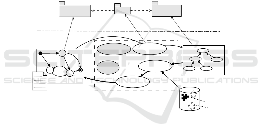
5.2 Improving Model Verification
Figure 6 shows the schema that will be studied and realised in the next research work:
the schema is in charge of defining the main blocks of the IMV functionality. As de-
scribed, the aim of such functionality is not only to check if the model is correct accord-
ing to defined syntax and semantics but also to provide a proper support in improving
the modelling experience by suggesting best and/or worst practises.
System Model
IMV
Patterns
Anti-Patterns
KB
Structural + Datatype
Description
Lexer &
Parser
Constraint
Checker
P&AP
Advisor
DSTM
<<metamodel>>
DSTM
<<ontology>>
Bridge
M2
M1
Model
Bridging
System Ontology
Inverse Model
Bridging
Fig. 6. An integrated reference schema for the IMV approach.
The process works as follows: the DSTM system model (both graphical descrip-
tion of the model structure as well as the textual definition of datatypes and variables)
is first processed by traditional techniques. As graphical model structure verification
phase can exploit modern model-driven technologies able to generate a model from a
graphical user interface that is already conform to a metamodel, the textual definition
of the datatypes must by processed by traditional parsers and lexers. After this phase,
a validation of semantic constraints are due in order to ensure that the model is well-
formed. Some examples of these constraints are: (i) a variable should be defined and
assigned to a type; (ii) a variable used in the DSTM model (e.g., in the definition of a
trigger) must be declared in the datatype file; (iii) a DSTM transition coming out from
a pseudo node must not have a trigger expressed (see for further details [31]).
45
Improving Automatic Test Case Generation Process with Knowledge Engineering in the Crystal Project
45
These activities traditionally retrieve to the user some exceptions in case the model
is not con formant to the syntax/semantics of the language. Furthermore, many confor-
mant models (i.e., raising no exception) may be improved by adopting common mod-
elling practises (patterns) or avoiding common pitfalls (anti-patterns). This activity is
performed by the Pattern & Anti-Pattern Advisor (P&AP Advisor) that is in charge of
reasoning on a ontology representing the DSTM model (System Ontology, i.e. ABOX)
and using available reasoning techniques and technologies. This reasoning activity is
in charge of substituting non-efficient sub-parts (the anti-patterns) of this ontology with
other more efficient ones (the patterns): both patterns and anti-patterns are contained
into a Knowledge Base (KB).
The means by which the DSTM System Model is translated into the System On-
tology are a Model Bridging and an Inverse Model Bridging transformations. Such
bridging functions are built implemented upon the definition of a proper bridge between
DSTM metamodel and ontology as described in Section 4.
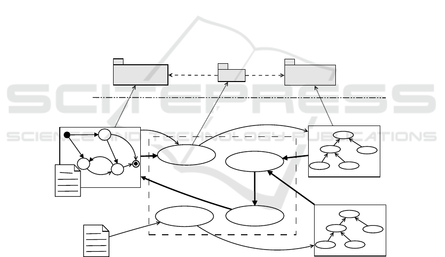
5.3 Improving Requirement-Model Mapping
A picture of a second integration way is reported in Figure 7 where Requirement An-
notation (RA) proposed process is depicted.
System Model
RA
Structural + Datatype
Description
Matcher
DSTM
<<metamodel>>
DSTM
<<ontology>>
Bridge
M2
M1
Model
Bridging
System Ontology
Inverse Model
Bridging
Requirements
NL
Analyser
Requirement Ontology
Fig. 7. An inter grated reference schema for the RA approach.
This process has the aim to aid the modeller in annotating the defined DSTM System
Model with requirements. Requirements are considered in DSTM for both traceability
purpose and to generate automatically Test Sequences on the base of the item of the
DSTM that is annotated with the requirement. In other words, when a requirement is
mapped onto a model transition, the Test Sequence related to that requirement consider
46
EPS Rome 2014 2014 - European Project Space on Computational Intelligence, Knowledge Discovery and Systems Engineering for Health
and Sports
46

the passage trough the model transition. Hence, annotating the model in an effective
and efficient way is an important task that Knowledge Engineering can improve.
The main idea is to consider a reasoner (the Matcher) able to match a System On-
tology and a Requirement Ontology. While the first can be obtained from the System
Model by exploiting the bridging technique already defined, the latter can rely on a
well-assessed research background on Natural Language Processing (NL Analyzer).
Once the match is done, an Inverse Bridging reports the annotations on the DSTM Sys-
tem Model.
6 Future Developements
The ontology-aware meta-pyramid offers several other benefits that can all be sum-
marised by the exploitation of the transformational techniques of the MDE and the
reasoning techniques of the KE. This chapter has defined a roadmap in the concrete
realization of a synergies of these two worlds in the context of an industrial-driven
research project: the Crystal project. By selecting one of the many Use Case of the
Crystal project, this chapter illustrates the main points where KE and MDE may find
their synergy.
Of course, this work describes an on-going research mainly by illustrating the main
next activity that involve both the research units of the University of Naples Federico II
and the Second University of Naples.
Acknowledgements. This paper is partially supported by research project CRYSTAL
(Critical System Engineering Acceleration), funded from the ARTEMIS Joint Under-
taking under grant agreement n. 332830 and from ARTEMIS member states Austria,
Belgium, Czech Republic, France, Germany, Italy, Netherlands, Spain, Sweden, United
Kingdom.
References
1. Aßmann, U., Zschaler, S., Wagner, G.: Ontologies, meta-models, and the model-driven
paradigm. In: Ontologies for Software Engineering and Software Technology. Springer
(2006) 249–273
2. Rinaldi, A.: A content-based approach for document representation and retrieval. In: Pro-
ceedings of the eighth ACM symposium on Document engineering, ACM (2008) 106–109
3. Thomas, R.: A translation approach to portable ontology specifications. Knowl. Acquis. 5
(1993) 199–220
4. Minsky, M.: A framework for representing knowledge. Technical report, Massachusetts
Institute of Technology, Cambridge, MA, USA (1974)
5. Woods, W.: What’s in a link: Foundations for semantic networks. In Bobrow, D.G., Collins,
A., eds.: Representation and Understanding. Academic Press, New York (1975) 35–82
6. Brachman, R.: What’s in a concept: Structural foundations for semantic nets. International
Journal of Man-Machine Studies 9 (1977) 127–152
7. Brachman, R.: On the epistemological status of semantic networks. In Findler, N.V., ed.:
Associative Networks: Representation and Use of Knowledge by Computers. Academic
Press, Orlando (1979) 3–50
47
Improving Automatic Test Case Generation Process with Knowledge Engineering in the Crystal Project
47

8. Brachman, R., Schmolze, J.: An overview of the Kl-ONE knowledge representation system.
Cognitive Science 9 (1985) 171–216
9. Fox, M., Wright, J., Adam, D.: Experiences with srl: an analysis of frame-based knowledge
representations. In: Proceedings from the first international workshop on Expert database
systems, Redwood City, CA, USA, Benjamin-Cummings Publishing Co., Inc. (1986) 161–
172
10. Bobrow, D., Winograd, T.: An overview of krl, a knowledge representation language. Tech-
nical report, Stanford University, Stanford, CA, USA (1976)
11. Guarino, N.: The ontological level. In Casati, R., B. Smith, B., White, G., eds.: Philosophy
and the Cognitive Sciences. Holder-Pichler-Tempsky, Vienna (1994)
12. Albanese, M., Maresca, P., Picariello, A., Rinaldi, A.: Towards a multimedia ontology sys-
tem: an approach using TAO XML. In: In Proceedings of the 11th International Conference
on Distributed Multimedia Systems (DMS’05). (2005) 52–57
13. Cataldo, A., Rinaldi, A.: An ontological approach to represent knowledge in territorial plan-
ning science. Computers, Environment and Urban Systems 34 (2010) 117–132
14. Dean, M., Schreiber, G.: OWL Web Ontology Language Reference. Technical Report
http://www.w3.org/TR/2004/REC-owl-ref-20040210/, W3C (2004)
15. Schmidt, D.C.: Guest editor’s introduction: Model-driven engineering. Computer 39 (2006)
25–31
16. (CRYSTAL: CRitical sYSTem engineering AcceLeration) http://www.crystal-artemis.eu/.
17. Pfl
¨
ugl, H., El-Salloum, C., Kundner, I.: CRYSTAL, CRitical sYSTem engineering AcceLer-
ation, a Truly European Dimension. ARTEMIS Magazine 14 (2013) 12–15
18. (CESAR: Cost-Efficient methods and proceses for SAfety Relevant embedded systems)
http://www.cesarproject.eu/.
19. (iFEST: industrial Framework for Embedded Systems Tools) http://www.artemis-ifest.eu/.
20. (MBAT: Combined Model-based Analysis and Testing of Embedded Systems)
http://www.mbat-artemis.eu/.
21. UIC: ERTMS/ETCS class1 system requirements specification, ref. SUBSET-026, issue 2.2.2
(2002)
22. CENELEC: Cenelec, en 50128: Railway applications - communication, signalling and pro-
cessing systems - software for railway control and protection systems (2011)
23. CENELEC: Cenelec, en 50126: Railway applications - demonstration of reliability, avail-
ability, maintainability and safety (rams) - part 1: Generic rams process (2012)
24. Marrone, S., Flammini, F., Mazzocca, N., Nardone, R., Vittorini, V.: Towards model-driven
v&v assessment of railway control systems. International Journal on Software Tools for
Technology Transfer 16 (2014) 669–683
25. Barberio, G., Di Martino, B., Mazzocca, N., Velardi, L., Amato, A., De Guglielmo, R., Gen-
tile, U., Marrone, S., Nardone, R., Peron, A., Vittorini, V.: An interoperable testing en-
vironment for ertms/etcs control systems. Lecture Notes in Computer Science (including
subseries Lecture Notes in Artificial Intelligence and Lecture Notes in Bioinformatics) 8696
LNCS (2014) 147–156
26. Amalfitano, D., Amatucci, N., Fasolino, A., Gentile, U., Mele, G., Nardone, R., Vittorini, V.,
Marrone, S.: Improving code coverage in android apps testing by exploiting patterns and
automatic test case generation. (2014) 29–34
27. Gentile, U., Marrone, S., Mele, G., Nardone, R., Peron, A.: Test specification patterns for
automatic generation of test sequences. Lecture Notes in Computer Science (including sub-
series Lecture Notes in Artificial Intelligence and Lecture Notes in Bioinformatics) 8718
LNCS (2014) 170–184
28. Gargantini, A., Heitmeyer, C.: Using model checking to generate tests from requirements
specifications. SIGSOFT Softw. Eng. Notes 24 (1999) 146–162
48
EPS Rome 2014 2014 - European Project Space on Computational Intelligence, Knowledge Discovery and Systems Engineering for Health
and Sports
48

29. Alur, R., Kannan, S., Yannakakis, M.: Communicating hierarchical state machines. In: Au-
tomata, Languages and Programming. Volume 1644 of Lecture Notes in Computer Science.
Springer Berlin Heidelberg (1999) 169–178
30. OMG: (Unified modeling language (uml), superstructure)
31. Gentile, U., Nardone, R., Peron, A., Benerecetti, M., Vittorini, V., Marrone, S.,
De Guglielmo, R., Mazzocca, N., Velardi, L.: Dynamic state machines for formalizing rail-
way control system specifications. (2015)
32. Steinberg, D., Budinsky, F., Paternostro, M., Merks, E.: EMF: Eclipse Modeling Framework
2.0. 2nd edn. Addison-Wesley Professional (2009)
33. Staab, S., Walter, T., Gr
¨
oner, G., Parreiras, F.: Model driven engineering with ontology tech-
nologies. In: Reasoning Web. Semantic Technologies for Software Engineering. Springer
(2010) 62–98
34. Favre, J.M.: Megamodeling and etymology-a story of words: From med to mde via model
in five milleniums. In: In Dagstuhl Seminar on Transformation Techniques in Software
Engineering, number 05161 in DROPS 04101. IFBI, Citeseer (2005)
35. Guizzardi, G., Herre, H., Wagner, G.: On the general ontological foundations of conceptual
modeling. In: Conceptual ModelingER 2002. Springer (2003) 65–78
36. Sowa, J.: Knowledge representation: logical, philosophical, and computational foundations.
(1999)
37. Niles, I., Pease, A.: Towards a standard upper ontology. In: Proceedings of the international
conference on Formal Ontology in Information Systems-Volume 2001, ACM (2001) 2–9
49
Improving Automatic Test Case Generation Process with Knowledge Engineering in the Crystal Project
49
