
Planning of Pushing Manipulation by a Mobile Robot Considering Cost
of Recovery Motion
Takahiro Saito, Yuichi Kobayashi and Tatsuya Naruse
Graduate School of Engineering, Shizuoka University, 3-5-1 Johoku, Naka-ku, Hamamatsu, Japan
Keywords:
Motion Generation, Developmental Robotics, Hybrid System, Mobile Robot.
Abstract:
This paper presents a planning method of pushing manipulation by a mobile robot. It is sometimes very useful
if the robot can take recovery action, namely, re-approaching and re-pushing, when it turns out to be ineffective
to keep current pushing motion. The proposed planning framework is based on the idea of mode switching,
where three modes; approaching, pushing and re-pushing, are considered. The pushing motion is first built
with dynamic programming, which provides value function of the state. Based on the value, planning of
re-approaching to the object and re-pushing is conducted using a value iteration algorithm extended to state
space with uncertainty. The proposed planning framework was evaluated in simulation, and it was shown that
it provides more effective behaviour of the robot by recovery motion at an appropriate timing.
1 INTRODUCTION
Today, robots that can work on behalf of humans
are expected in various fields such as rescue, guide
and nursing-care (Tribelhorn, 2007; Nagatani, 2011;
Mukai, 2010). In some applications, it is very impor-
tant that the robots can act autonomously to reduce
cost of human controllers. The autonomous behav-
iors of the robots include action to manipulate ob-
ject of interest as well as to drive the robots them-
selves. Considering the ability of manipulation of the
autonomous robots widens applicability of them, but
makes planning and control problems more compli-
cated, partly because of larger gap between the model
of the world and actual behavior of the real system.
One promising approach to the incompleteness of
the world model is to apply numerical (or learning)
approaches, which do not rely on specific mathemat-
ical model of the world. A numerical approach to
solve optimal control problem is known as DP (Dy-
namic Programming) (Bertsekas, 2005). Reinforce-
ment learning (Sutton and G.Barto, 1998), which re-
lies only on robot’s trial and error, has been exten-
sively applied to robot control problems including
whole-body dynamical motion of robot (Morimoto
and Doya, 2001).
With regard to manipulation task, Kondo etal.
(2003) realized pushing manipulation of a peg based
on reinforcement learning. Reinforcement learning
approaches, however, generally suffer from increas-
ing number of trials required for behavior acquisition.
Similar problem also happens to dynamic program-
ming approaches since calculation amount of DP can
easily increase according to the dimension of the state
space.
Complexity of manipulation problem is caused by
several reasons; increase of search space due to com-
binatorial problem of contact points between robot
and object, uncertainty of object dynamics at its con-
tact points and switching of contact modes such as
stick, slip, rolling and sliding. The last one has been
discussed in the framework of hybrid dynamical sys-
tem (van der Schaft and Schumacher, 2000). The
framework of hybrid dynamical system deals with
a problem where a continuous dynamical system is
called a mode and a different continuous dynamics
appears when switching of mode happens. By uti-
lizing the structure of the task considering multiple
modes, efficiency of learning approach to manipula-
tion can be improved (Kobayashi and Hosoe, 2010).
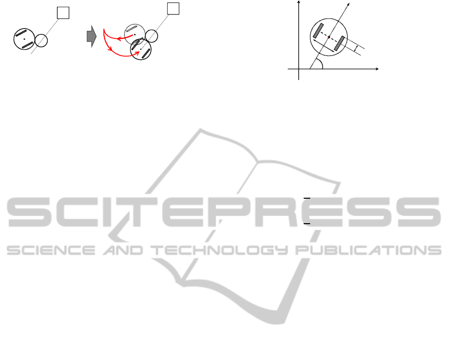
Pushing task by a mobile robot can be also re-
garded as a class of the hybrid dynamical system,
where the task can be divided into non-contact (ap-
proaching) mode and contact (pushing) mode. Some-
times it will be effective to replan the robot’s motion
to once leave contact mode for re-approach to the ob-
ject when displacement of the object is getting too
large as depicted in Fig. 1. Though there has been an
attempt to consider mode switching to manipulation
by a mobile robot (Sekiguchi et al., 2012), uncertainty
322
Saito T., Kobayashi Y. and Naruse T..
Planning of Pushing Manipulation by a Mobile Robot Considering Cost of Recovery Motion.
DOI: 10.5220/0005156203220327
In Proceedings of the International Conference on Neural Computation Theory and Applications (NCTA-2014), pages 322-327
ISBN: 978-989-758-054-3
Copyright
c
2014 SCITEPRESS (Science and Technology Publications, Lda.)
G
Object
Goal
Robot
G
Object
Goal
Robot
Figure 1: An example of re-pushing behavior.
in the process of pushing was not sufficiently consid-
ered. This paper presents a planning of pushing ma-
nipulation by a mobile robot including recovery mo-
tion (re-pushing) considering uncertainty of object’s
position.
In the remainder, Section 2 describes problem set-
tings of pushing manipulation. The proposed plan-
ning method is described in Sections 3 and 4, where
approaching behavior and re-pushing behavior are
considered, respectively. Evaluation by simulation is
described in Section 5, followedby conclusion in Sec-
tion 6.
2 PROBLEM SETTING
A task of pushing manipulation by a mobile robot
is considered. The mobile robot has two wheels, to
which rotational speed commands are sent. A circu-
lar object is located at an initial position that is apart
from the robot. The objective is to carry the object to
goal region in the shortest time.
If the robot fails to push the object to the goal re-
gion, it has to retry the task, which requires longer
time. Thus, the robot is required to consider risk of
failing to reach the goal region through the increase
of expected time for task completion. It can reduce
the risk by taking re-pushing action depending on sit-
uations. It is assumed that the robot can observe po-
sitions of the goal and the object and there are no ob-
stacles.
Fig.2 shows the model of two-wheeled robot.
Each variable is defined as follows.
• x, y : Coordinates of the point P [mm]
• θ : Orientation of robot to the x-axis [rad]
• ω
r
, ω
l
: Angular velocity of the wheel [rad/sec]
• R : Radius of the wheel [mm]
• L : Length of the axle [mm]
Kinematics of the forward motion of robot is ex-
pressed by the following equation.
Direction
of robot
y
x
P
L
R
l
ω
r
ω
θ
Figure 2: Model of two-wheeled robot
˙x
˙y
˙
θ
=
cosθ/2 cosθ/2
sinθ/2 sinθ/2
1/R 1/R
Rω
r
Rω
l
(1)
Position and orientation of the robot can be obtained
by integrating (1) as
x = x
0
+
R
2
Z
t
0
cosθ(t)(ω
r
+ ω
l
)dt (2)
y = y
0
+
R
2
Z
t
0
sinθ(t)(ω
r
+ ω
l
)dt (3)
θ = θ
0
+
Z
t
0
(ω
r
− ω
l
)dt, (4)
where x
0
, y
0
, θ
0
denote position and orientation of the
robot at time t = 0.
3 PLANNING OF APPROACHING
AND PUSHING BEHAVIORS
3.1 Motion Generation based on DP
Motion planning of each behavior is based on DP. Let
s ∈ S denote discrete state and a ∈ A denote action,
where S and A denote sets of states and actions, re-
spectively. Transition probability from state s to s
′
by taking action a is denoted by P
a
ss
′
, where s,s
′
∈ S
and a ∈ A . R
a
ss
′
denotes expected reward given to the
robot for state transition from s to s
′
with action a.
The objective of motion planning is to obtain a con-
trol policy a = π(s) which maximizes cumulated re-
ward
∑
∞
k=1
γ
k−1
R
a
ss
′
, where 0 < γ ≤ 1 denotes discount
factor.Discount factor is an index for evaluating by
discounting the reward obtained in the distant future.
The optimal Bellman equation is expressed by the fol-
lowing
V(s) = arg max
a
∑
a
π(s,a)
∑
s
′
P
a
ss
′
[R
a
ss
′
+ γV(s
′
)], (5)
where V(s) denotes state value function. By iterat-
ing update of the equation, called value iteration, for
all s ∈ S , value function of each state under the opti-
mal control policy is obtained. In this paper, motion
PlanningofPushingManipulationbyaMobileRobotConsideringCostofRecoveryMotion
323

planning with DP is used to obtain control policies for
approaching motion and pushing motion.
The value iteration algorithm is shown below,
where ε denotes a small positive value to judge con-
vergence.
Algorithm 1: Algorithm of Dynamic Programming.
The initialized with the value of any V.
V(s) ← 0
Repeat :
For each s ∈ S
v ← V(s)
V(s) ← max
a
∑
s
′
P
a
ss
′
[R
a
ss
′
+ γV(s)] (6)
∆ ← max(∆,|v−V(s)|)
∆ < ε
output the policy π
π(s) = arg max
a
∑
s
′ P
a
ss
′
[R
a
ss
′
+ γV(s)]
3.2 Generation of Approaching
Behavior
Model of two-wheeled robot for non-contact mode is
shown in Fig.3. Non-contact mode denotes a state
where the robot approaches the target. State of robot
in the non-contact mode, x ∈ R
3
, and control input
u ∈ R
2
are defined as
x = (x
r
,y
r
,θ)
T
,u = (ω
l
,ω
r
)
T
, (7)
where x
r
, y
r
are the position of the robot and θ is the
posture of the robot. ω
l
, ω
r
are the rotational speeds
of the left and right wheels, respectively.
The robot must reach an appropriate place to start
pushing the object. A point on the opposite side of the
line to the goal is target point.
3.3 Generation of Pushing Behavior
Model of two-wheeled robot for Contact mode is
shown in Fig.4. Contact mode is a state where the
robot pushes the object. State of the robot in the con-
tact mode, x ∈ R
4
, and control input u ∈ R
2
are de-
fined as,
x = (x
r
,y
r
,θ,φ)
T
,u = (ω
l
,ω
r
)
T
, (8)
where φ denotes the orientation of the object relative
to the robot. The target position of the object is de-
fined as (x
g
, y
g
). The target state for the pushing be-
havior is a state where center of the object is inside a
square with size R
g
[mm] at (x
g
, y
g
).
y
x
θ
r
ω
l
ω
Figure 3: Non-contact mode.
y
x
φ
θ
r
ω
l
ω
Figure 4: Contact mode.
X
2
Current
configuration
Non-contact
mode
Mode
transition
Contact
mode
X
1
X
3
Desired
configuration
Re-pushing
Figure 5: Planning space shift among different modes.
4 PLANNING OF RE-PUSHING
BEHAVIOR
4.1 Uncertainty in Pushing
Manipulation
If the robot could reach the desired position for push-
ing given in section 3.2 without any error, the object
would reach the goal position only with completely
straight locomotion of the robot. In the implementa-
tion of the approaching behavior, however, there is an
inherent error caused by discretization of the state. It
is required to consider deviation of object trajectory
even with the planned pushing behavior described in
section 3.3.
It will be better to stop continuing current pushing
motion and to take approaching behavior again when
deviation of the object it too large to safely move to
the goal region. This behavior is called re-pushing
in this paper. The core contribution of the paper is
to realize an appropriate planning when to take re-
pushing action. Since approaching behavior inher-
ently includes error at the destination, the re-pushing
behavior should be planned considering uncertainty
of position of the object.
The outline of mode transitions in pushing and re-
pushing behaviors is shown in Fig.5. After reaching
the contact mode, the robot proceeds toward the de-
sired configuration while keeping the contact mode.
But if necessary, it once switches to non-contactmode
not to fail to reach the goal region. This decision of
re-pushing can be made by considering both costs of
NCTA2014-InternationalConferenceonNeuralComputationTheoryandApplications
324
keeping current pushing behavior and switching to re-
pushing behavior. Note that ‘cost’ used in the follow-
ing has the same meaning as ‘reward’ with multipli-
cation of -1.
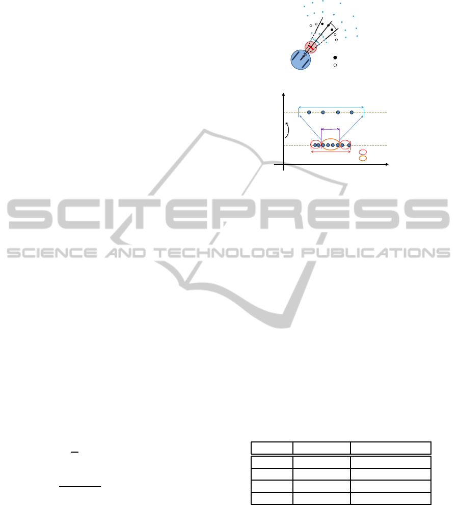
4.2 Planning of Re-pushing Behavior
Uncertainty of object behavior is considered using
particles (Thrun et al., 2005) that express various po-
sitions of the object. Initially, particles are located
randomly according to size of a discrete state used in
approaching behavior, as shown in Fig. 6. Variance
of the object position is expressed by range of distri-
bution of the particles. Let φ
j
, j = 1, ··· , M denote
j-th discretized range of the object position relative to
the goal direction, which corresponds to a state where
particles are distributed in interval of [−φ
j
φ
j
]. Dis-
tance of the robot to the goal is also discretized and
denoted by r
i
,i = 1,· ·· ,K. Thus, state of the robot
and the object with uncertainty is represented by dis-
crete state of (r
i
, φ
j
), i = 1,··· ,K, j = 1,··· ,M (see
Fig.7).
Decision of taking re-pushing action is expressed
by a threshold of φ, denotes by φ
a
, where re-pushingis
conducted if the relativeangle of the object to the goal
direction exceeds φ
a
. Expected cost for taking action
φ
a
in state (r
i
, φ
j
) can be estimated by the particles
that are located inside the region defined by φ
j
. Now
let N
1
particles are inside the region defined by φ
a
and
N
2
particles are outside. Expected cost for continuing
current pushing behavior can be estimated by eval-
uating the N
1
particles. N
2
particles can be utilized
to estimate expected reward for taking re-pushing be-
havior. Now let V(r
i
, φ
j
) denote value (expected cu-
mulated cost) at state (r
i
, φ
j
). The evaluation can be
done by applying the value iteration framework in the
following form:
V(r
i
,φ
j
) = min
φ
a
1
N
"
N
1
(φ
j
,φ
a
)
∆t +V(r
i−1
,φ
′
j
)
+N
2
(φ
j
,φ
a
)
1
N
2
(φ
j
,φ
a
)
N
2
∑
k=1
d(φ
k
) +V(r
i
,φ
0
)
#
,
(9)
where φ
k
denotes position of k-th particle and d(φ
k
)
denotes cost for re-approaching behavior starting
from state φ
k
. N
1
(φ
j
,φ
a
) and N
2
(φ
j
,φ
a
) denote num-
ber of particles inside and outside of region defined
by re-pushing threshold φ
a
in state φ
j
, respectively.
a
φ
: Re-pushing
: Continue pushing
Figure 6: Variation in the position of the object.
r
i
r
i-
1
: re-pushing
: continue pushing
φ
j
φ
a
φ
j
φ
′
t∆
Figure 7: The idea of re-pushing.
5 EXPERIMENT
5.1 Experimental Condition
To evaluate the effectiveness of the proposed method,
re-pushing behavior with fixed threshold values φ
a
=
10 and φ
a
= 20 were implemented. Performance of
each strategy was evaluated by repeated trials with
different initial positions of (x, y, θ, φ). Size of the
goal region was defined as 20 mm.
The specifications of the robot and the object used
in the simulation were given by the followings; radius
of the wheel 20mm, length of the axle of the robot
50mm, radius of the robot 25mm, radius of the object
15mm. Table 1 depicts the number of discretization
of the state space for the contact mode and the non-
contact mode.
Table 1: the number of divisions of the discretization.
State space Division number
x [mm] [0, 250] 26
y [mm] [0, 250] 26
θ [deg] [0, 360] 36
φ [deg] [-30, 30] 13
Initial configuration of the robot was fixed at (x, y,
θ)=(7,7,45) and initial position of the object was var-
ied from -10 to 10 degree with one degree intervals.
Discretization of action was given as 20 motions, 2
for turning to the left and the right, 9 for forward and
9 for backward locomotions.
PlanningofPushingManipulationbyaMobileRobotConsideringCostofRecoveryMotion
325
0 5 10 15 20 25
0
5
10
15
20
25
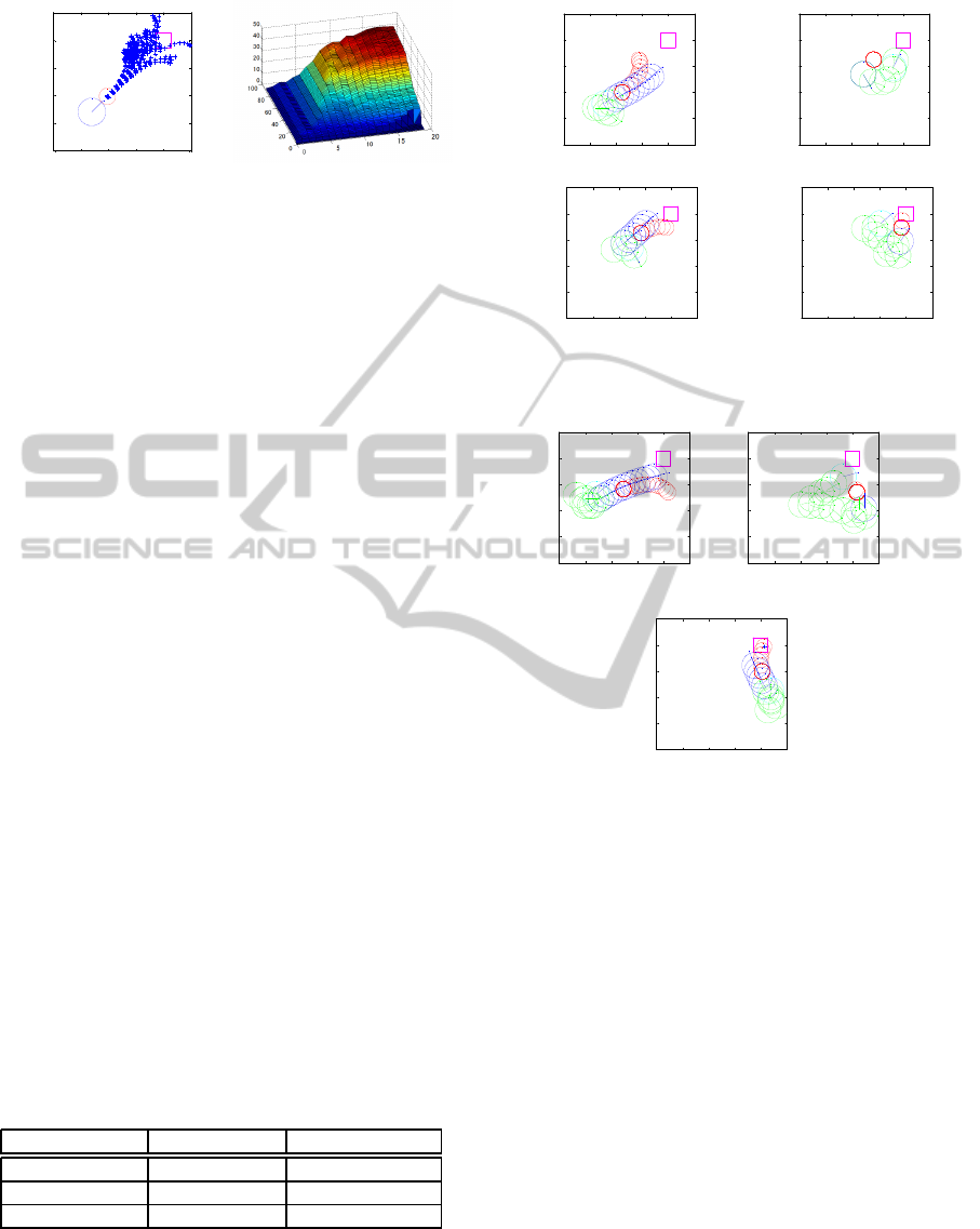
Figure 8: Prediction of
the position of a subject
with a particle.
j
φ
r
i
V
Figure 9: Value calculation
results for determining the
range.
5.2 Experimental Result
An example of particle simulation is shown in Fig.
8. ‘+’ in the figure depicts position (particle) of the
object. Initially particles were located in front of the
robot with a small variation. It can be seen that posi-
tions of the object diverged even with a small initial
variation.
The value calculation results by the dynamic pro-
gramming is shown in Fig.9. It can be seen that value
of state expected cost is higher when r
i
(distance to
the goal) is larger and φ
j
(variance of object position)
is larger. The obtained value function can be used to
plan re-pushing actions.
The result of comparison between the proposed
method and re-pushing strategy with fixed threshold
is depicted in Table 2. Success rate in the table de-
notes ratio of reaching inside the goal region. It can be
seen that proposed method realized the best success
ratio. Average steps required to reach the goal region
was also the best compared with the fixed threshold
strategies.
An example of trajectory realized by the proposed
re-pushing planning is shown in Fig. 10, where the
object is denoted by red circles. Blue circles de-
note the robot when it was pushing the object and
green circles denote the robot with approaching (non-
contact) mode. First it continued pushing motion until
the object turns away from the goal (a). The first re-
pushing was applied by re-approaching (b) and push-
ing (c). The robot finally moved the object to the goal
region after the second re-pushing (d).
Table 2: Experimental result.
Success rate Average of steps
Present method 71.4% (15/21) 50.4
φ
a
= 20 52.4% (11/21) 74.3
φ
a
= 10 57.1% (10/21) 52.2
There were failures of the pushing task both in the
proposed framework and the fixed re-pushing strate-
gies. They were caused by incompleteness of the
control policy obtained by DP. Discretization of the
state space was not sufficiently fine so as to enable
0 5 10 15 20 25
0
5
10
15
20
25
(a)
0 5 10 15 20 25
0
5
10
15
20
25
(b)
0 5 10 15 20 25
0
5
10
15
20
25
(c)
0 5 10 15 20 25
0
5
10
15
20
25
(d)
Figure 10: Trajectories of robot and object divided into four
phases.
0 5 10 15 20 25
0
5
10
15
20
25
(a)
0 5 10 15 20 25
0
5
10
15
20
25
(b)
0 5 10 15 20 25
0
5
10
15
20
25
(c)
Figure 11: An example which is larger number of steps as
compared to the fixed value.
the robot to take appropriate action at every discrete
state. Increasing the discretization number also for
the robot’s action will improve success rate of the
task.
An example of trajectory that took many steps to
reach the goal is shown in Fig. 11. In this case, the
robot decided to take re-pushing at the last frame in-
dicated in (a), but it took many steps to re-approach
the object. This inefficiency might have been caused
by the calculation of value function based on (9). In
the framework, distance of the robot from the goal
was considered in addition to the variance of the ob-
ject position φ. Taking distance of the object from
the goal into account will also contribute to improve
planning of the re-pushing.
NCTA2014-InternationalConferenceonNeuralComputationTheoryandApplications
326
6 CONCLUSIONS
In this paper, we presented a method of generating an
object-pushing manipulation for a two-wheeled robot
based on consideration of effectiveness of re-pushing
and idea of mode switching. The task of pushing ma-
nipulation was divided into two phases; approaching
and pushing, both which DP was applied to. Planning
frameworkunder the consideration of uncertainty was
proposed to find appropriate timing for re-pushing
action decision. Simulation results showed that the
proposed planning framework realized better perfor-
mance in comparison with a re-pushing strategy with
a simple rule. The proposed framework will be fur-
ther improved not only for taking recovery motion but
also expansion to manipulation problem under coop-
eration of multiple mobile robots.
ACKNOWLEDGEMENTS
This research was partly supported by Tateishi Sci-
ence and Technology Foundation and Research Foun-
dation for the Electrotechnology of Chubu.
REFERENCES
Bertsekas, D. (2005). Dynamic Programming and Optimal
Control. Athena Scientific.
Ghosh, A., Chowdhury, A., Konar, A., and Janarthanan, R.
(2012). Multi-robot cooperative box-pushing prob-
lem using multi-objective particle swarm optimization
technique. In Information and Communication Tech-
nologies, pages 272–277.
Kobayashi, Y. and Hosoe, S. (2010). Planning-space shift
motiongeneration : variable-space motion planning
toward flexible extension of body schema. In Journal
of Intelligent and Robotic Systems, volume 62, pages
467–500.
Kondo, T. and Ito, K. (2003). A study on designing con-
troller for peg-pushing robot by using reinforcement
learning with adaptive state recruitment strategy. In
SICE Annual Conference.
Mas, I. and Kitts, C. (2012). Object manipulation using co-
operative mobile multi-robot systems. In Proceedings
of the World Congress on Engineering and Computer
Science.
Morimoto, J. and Doya, K. (2001). Acquisition of stand-
up behavior bya real robot using hierarchical rinforce-
ment learning. In Robotics and Autonomous Systems,
volume 36(1), pages 37–51.
Mukai, T., Hirano, S., H.Nakashima, and Kato, Y. (2010).
Development of a nursing-care assistant robot riba
that can lift a human in its arms. In Intelligent Robots
and Systems.
Nagatani, K., Kiribayashi, S., and Tadokoro, S. (2011). Re-
design of rescue mobile robot quince. In Safety, Secu-
rity, and Rescue Robotics.
Sekiguchi, T., Kobayashi, Y., Shimizu, A., and Kaneko, T.
(2012). Online learning of optimal robot behavior for
object manipulation using mode switching. In Proc.
of IEEE Int. Symposium on Robotic and Sensors En-
vironments, volume 61-66.
Sutton, R. S. and G.Barto, A. (1998). Reinforcement Learn-
ing. MIT Press.
Theodorou, E., Buchli, J., and Schaal., S. (2010). Re-
inforcement learning of motor skills in high dimen-
sions:a path integral approach. In In International
Conference on Robotics and Automa-tion.
Thrun, S., Burgard, W., and Fox, D. (2005). Probabilistic
Robotics. The MIT Press.
Tribelhorn, B., Mudd, C. H., and Dodds, Z. (2007). Eval-
uating the roomba: A low-cost, ubiquitous platform
for robotics research and education. In Robotics and
Automation.
van der Schaft, A. and Schumacher, H. (2000). An intro-
duction to hybrid. In Dynamical Systems.
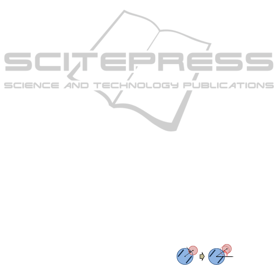
APPENDIX
Position of the Object at Impact
This section is describes behavior of the object when
the object and the circular robot collides. When the
robot has interfered to the object by distance d, the
object is moved to a position in contact with the robot
on an extended line connecting the centers of the ob-
ject and the robot. The position of the robot is not
changed by the interference. Let the previous position
of the object be denoted by (x
ob
,y
ob
), and the angle
between x-axis and line segment connecting the cen-
ters of the object and the robot be denoted by ψ. Then
position of the object after the collision (x
ob
,y
ob
) is
expressed by the following equation.
x
oa
= x
ob
+ d cosψ (10)
y
oa
= y
ob
+ d sinψ (11)
d
ψ
Figure 12: Position of the object after contact with the
robot.
PlanningofPushingManipulationbyaMobileRobotConsideringCostofRecoveryMotion
327
