
HiPro-CodeGen
Automatic Programming for Parallel Numerical Simulations
Liao Li, Jing Cuiping, Wang Wei, Zhang Aiqing and Yang Zhang
Institute of Applied Physics and Computational Mathematics, No. 2, East Fenghao Road, Beijing, China
Keywords: High Performance Computing, Source Code Generation, Graphical Programming, Parallel Programming,
Component-based Programming.
Abstract: HiPro-CodeGen is a code generation engine designed for numerical simulation development. Its central
objective is to produce a parallel software framework with standard structure for an application developed
on JASMIN, a domain-specific computational framework. The unique parallel part and all interfaces of the
application are generated and implementation of sequential subroutines is the only part of the code left to be
written manually for a programmer. The design and implementation of the code generation engine is
introduced which combines numerical mathematics with component-based programming to create
ontological models for parallel simulations. A hybrid programming method is proposed on the work
mechanism of the engine which combines graphical and textual approaches to hide parallel programming
and object-oriented programming from developers. A real application is presented to show the effectiveness
and efficiency of the engine.
1 INTRODUCTION
Numerical simulation is an important method to
explore the evolution of physical systems by
scientists in current age (Mo, Pei, 2009). With the
development of high performance computing,
simulation is leading to high accuracy and high
confidence in scientific study. Developing a
scientific simulation covers implementing scientific
methodology, algorithms, and programming models,
and virtually always each advance has been
accompanied by increases in the complexity of the
underlying software. At the same time, the computer
industry has continued to create ever larger and
more complex hardware in an attempt to satisfy the
increasing demand for simulation capabilities
(Benjamin, 2006). These architectures tend to
exacerbate the complexity of software running on
these systems. Modern programmers may repeatedly
rewrite applications to expose incrementally more
parallelism for each next generation of hardware. It
requests a programmer be knowledgeably aware of
new software and hardware. Admittedly, this is a
demanding task for current programmers most of
which are engaged in researching on physics and
mathematics, because they have been trained in
sequential programming. We are facing a fact that
difficulties on parallel programming embarrass the
development of high performance numerical
simulations.
To ease the coding issues many studies on
graphical programming and automated code
generation techniques have been given on
developing parallel applications. Boris etc. develop
an integrated development environment for visual
parallel programming (Boris, 2006). It is not
effective to develop complicated numerical
simulations because of limitation on graphical
operations. MatLab also gives some parallelism
capabilities with parallel computing toolbox while
the scalability and the performance of the program
are limited by its parallel computing mechanism.
Experience says that programming in graphic
form completely is embarrassed on solving the
problems especially developing numerical
simulations because of the complexities of
simulations and the limitations of the graphical
programming technology. Liao etc. propose a hybrid
programming approach which combines graphical
and textual programming to solve the problem by
shielding parallel programming details and object-
oriented programming languages for developing
scientific applications based on JASMIN.
125
Li L., Cuiping J., Wei W., Aiqing Z. and Zhang Y..
HiPro-CodeGen - Automatic Programming for Parallel Numerical Simulations.
DOI: 10.5220/0005089101250131
In Proceedings of the 9th International Conference on Software Engineering and Applications (ICSOFT-EA-2014), pages 125-131
ISBN: 978-989-758-036-9
Copyright
c
2014 SCITEPRESS (Science and Technology Publications, Lda.)

In this paper we present the design and
implementation of the code generation engine which
supply the automatic programming capabilities
given in HiPro (Liao,2013), originally named with
IDE-JASMIN. The content of this paper is organized
as follows. Section 2 analysis the features of parallel
programs developed on JASMIN. In section 3, the
design of the code generation engine which utilizing
the features to create topological model is presented
in detail. In section 4, we show the advantages of
using HiPro-CodeGen to develop a computational
fluid dynamic parallel numerical simulation program
in the system. Then we present our conclusion and
point to directions for future work.
2 FEATURE MODEL OF A
PARALLEL NUMERICAL
SIMULATIONS
JASMIN abstracts a general framework from
numerical simulation domain and provides large
granularity software reuse in scientific high-
performance computing (Mo, 2010). The framework
tends to isolate the increased complexity of the
software and operating environment from the
programmers and utilize state of art technologies to
extract the maximum possible performance. It
facilitates problem solving with encapsulation of
parallel computing and communication through
patch-based data structures and component-based
mechanism which shield data decomposition and
communication from the users. Generally numerical
simulations share many common features. These are
utilized in JASMIN to provide a more normative
architecture for developing a parallel program. We
define a feature model to illustrate a numerical
simulation developed based on JASMIN. It is used
to direct the design of the hybrid graphical
programming interface. The model includes five
parts which are described in the following
subsections.
Before we introduce the model, to describe the
construction features of a numerical simulation, we
give some key concepts:
Level strategy class: strategy class which is
responsible for dealing with the computation on
global region. Programmers must implement
some strategy procedures which are implicitly
called by JASMIN.
Patch strategy class: strategy class specially
serves for an integrator component. It is
responsible for dealing with the computation on
a patch domain which is part of the global
region. Programmers must implement some
strategy procedures which are implicitly called
by JASMIN.
Integrator component: a parallel computation
mode defined in JASMIN. It is invoked in a
level strategy class and implicitly calls
procedures defined in its registered patch
strategy class.
Numerical kernel: A kind of subroutine to
implement part of numerical computational
method. It is a sequential program.
2.1 Data Structure and Numerical
Algorithm
Generally numerical simulation is solving a system
of PDEs or ODEs with numerical methods on a
discrete grid. JASMIN supports development of
structured grid application of two types including
rectilinear and deforming grid (Mo, 2009). Figure 1
shows the two-dimensional example grids often-
used in numerical simulations. Data parallelism is
the main form of parallelization of computing. In the
kind of parallelism, as is showed in Figure 2, the
region is decomposed into many domains during the
process of the computation. Each domain is
extended with ghost zones to satisfy the need of
numerical scheme. In JASMIN, three kinds of
coordinate system are available: Cartesian,
cylindrical and spherical coordinates. Grid type and
coordinate system determine the mesh description
mode in a program.
A physical variable, which also named with field
variable, is defined on the special position of the
Figure 1: Rectilinear and deforming grid used in structured
appliations.
Figure 2: Domain decomposition for data parallelism.
ICSOFT-EA2014-9thInternationalConferenceonSoftwareEngineeringandApplications
126

Cell Node Side-X Side-Y Particle
Figure 3: Discretization types of variables in a numerical
simulation.
discretization grid, such as cell, node, side or face
etc., as illustrated in Figure 3.
The numerical algorithm usually involves time
iterations with given initial conditions, i.e. time
integration algorithm. A complex algorithm is
broken down into smaller and manageable parts.
These parts are arranged to be executed adhering to
some rules. Figure 4 shows the flowchart of a
general time integration algorithm. Generally the
algorithm involves four key modules which are
organized in a loop and the user provides parameters
to control the stop of it. All modules should be
implemented according to the concrete computation.
Start
Initialization
Evaluatetimeste
p
Advance1ste
p
Acce
p
tsolution
E
nd
Continue?
Figure 4: A general flowchart presenting time integration
algorithm.
Generally developers are used to programming
numerical subprograms in Fortran, which is a
conventional textual, linear programming language
that is familiar to programmers who engaged in the
sequential numerical simulation development.
Component architecture have been used for high
performance scientific computing for years(Parker,
2002). Parallel integrator components are proposed
to encapsulate parallel computing details on patch-
based data structure (Mo, 2009). Parallelism is
obtained by creating integrator components to
encapsulate sequential numerical subroutines.
Components encapsulate much of the complexity of
parallelism inside a black box such as invoking MPI
or OpenMP interfaces and utilizing multi or many-
cores CPU in modern machines. We support user to
implement his computational method in sequential
numerical subroutines while parallelism is
accomplished in integrator components. The
separation makes hybrid programming of combining
graphical and textual programming feasible.
2.2 Application Architecture and
Program Organization
Domain experts develop parallel numerical
applications by assembling configured parallel
integrator components in a flowchart of time
integrator algorithm. For each component carrying
on computation task a patch strategy must be
implemented and the object of it be registered to the
component. Some virtual interfaces must be
implemented in C++ language and in which, data of
field variables is fetched via patch object and passed
to a numerical kernel invoked. Therefore parallelism
for a computational module is achieved by
connecting the component with real numerical
kernels. These components provide interfaces or
ports to be invoked in level strategy. As is shown in
figure 5, the application architecture model includes:
Main program
A level strategy class which deals with
assembling components.
Patch strategy classes. For each component
some specific procedures must be implemented
in a patch strategy class to invoke sequential
numerical subroutines to accomplish numerical
computation. The number of the patch strategy
classes is determined by the number of the
components created.
Sequential numerical subroutines
MainProgram.C
VariableManager
TypeDefinations.h
AppLevelStrategy
AppFort.h
Comp‐1
Comp‐2
Comp‐n
ICPComp‐1
ICPComp‐2
ICPComp‐n
.
subprog‐1
subprog‐2
subprog‐n
.
subprog‐3
Subroutines
ProgramsandClasses
ofCommon
Archetecture
Component
Objectes
PatchStrategy
Classes
Figure 5: Architecture of an application and invoking
model.
3 DESIGN OF HiPro-CodeGen
To develop a parallel program of numerical
simulation the user must write program to:
HiPro-CodeGen-AutomaticProgrammingforParallelNumericalSimulations
127

Define variables.
Code sequential computation kernels.
Create parallel integrator components.
Assemble components in the time integration
algorithm to construct a parallel program.
Deal with physical model described in an input
file.
Output physical variables for visual analysis.
Create a main procedure to organize issues
listed above.
HiPro is designed to offer graphical
programming capability to develop parallel
numerical simulations. The system implements a
graphical domain-specific programming language
combined with textual editor to support parallel
programming. The idea of parallel design combined
with sequential coding is achieved in the visual
programming environment.
According to the application model described in
section 2, the programming task is classified into
two types: configured on GUI and processed
automatically. Upon this we shield most of them as
best as we can in the programming system.
Therefore to construct a numerical simulation
program only the first four things of those which are
mentioned at the beginning of this section left to the
programmer to deal with. The other issues are
handled automatically. This mechanism releases the
user from complex programming. HiPro-CodeGen is
the core of HiPro system which is responsible for
generating codes. Next we introduce the working
mechanism in HiPro-CodeGen according to the four
tasks separately.
3.1 Define Variables
Variables in a scientific numerical simulation are
classified into three categories according to their
functionality and source, they are: grid variables,
physical variables and grid independent ones. The
classification is used to standardize interface
definition for a procedure and build type match
filtering when the procedure is called. Three variable
databases are created to store the variables. They are
physical variable DB, general variable DB and input
parameter DB.
A grid variable gives the definition of a domain.
As noticed, no database is created for grid variables.
In fact, grid ones are created automatically. There
are two build-in grid variables in the system. One is
used to describe the patch domain and the other is
used to give the information of ghost zones. This is
vitally important for the system design because we
use them to normalize the interface definition of
numerical subroutines.
The type definition of rectilinear grid variable for
a patch domain in C and C++ is
Typedef struct {
int ilo[NDIM];
int ihi[NDIM];
double xlo[NDIM];
double dx[NDIM];
} geom_t
The definition of that for deforming grid is
similar with it which only needs the first two
parameters. Comparative definition of them in
Fortran shares the same form using derived types.
We leave it out here for simplicity. The type
definition for ghosts is
Typedef struct {
int ilo[NDIM];
int ihi[NDIM];
int btype;
int location;
int condition;
} ghost_t
For physical variables, we give a set of domain-
specific data types listed in Table 1.
Domain-specific data type: a kind of data type
used for describing the discretization form of a
physical variable specially defined in a
numerical simulation.
Table 1: Domain-specific data types.
Type Properties
Cell Element type, Depth, Ghost width
Node Element type, Depth, Ghost width
Side-X Element type, Depth, Ghost width
Side-Y Element type, Depth, Ghost width
Group
Cell
Element type, Depth, Ghost width, Number of
groups
Group
Node
Element type, Depth, Ghost width, Number of
groups
Table 2: Supplementary data type.
Type Properties
Generic Element type, Depth
To describe the general variables we supplement
the type list with a special one, as is shown in the
Table 2. Upon this we extend data types to cover all
variables in JASMIN. These extensions are
necessary to support full application development in
scientific and engineering computing.
ICSOFT-EA2014-9thInternationalConferenceonSoftwareEngineeringandApplications
128
Programmer defines a variable through graphical
user interfaces interactively while the system will
invisibly generates the corresponding source code of
it. For instance, the code of a physical variable of
Cell type for a two dimensional application is given
as below:
integer :: gw_varName(0:1)
ElementType [,IntentType]:: varName
(geom%ilo(0)-gw_varName(0) :
geom%ihi(0)+gw_varName(0),
geom%ilo(1)-gw_varName(1) :
geom%ihi(1)+gw_varName(1))
3.2 Program Sequential Numerical
Subroutines
In the system numerical subroutines are classified
into three categories:
(Sub I) Execute computation on a domain.
(Sub II) Fill physical boundary.
(Sub III) Process grid independent variables
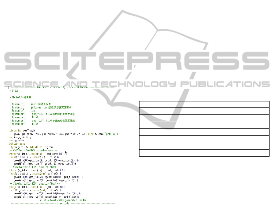
Figure 6: Generated code for a numerical kernel interface
in Fortran 90.
Requirements of dummy parameters are different
according to the classification. For example, no
dummy parameter of physical variable type is
permitted in the third category. A parameter of
geom_t is absolutely necessary in the first and
second category and ghost_t is mandatory in the
second one. There must be one and only one
parameter of such type. The classification is used to
build interface requirement match for integrator
component definition.
We use Fortran 2003 as the programming
language for coding numerical subroutines. The
code of interface definition is generated and inserted
into the beginning of the program file automatically.
This approach frees users from error-prone and
tedious type definitions and variable declarations.
Figure 6 shows an example code generated for a
subroutine. The code will be updated and replace the
older one when the user modify the definition
through GUI.
3.3 Create Parallel Integrator
Components
A type library of component is provided in the
system. Each type of components performs some
kind of well defined task and has specially designed
GUI. Available types of integrator components and
their functional properties are listed in Table 3. The
property specifies acceptable categories of
subroutines and whether this kind of component
needs to register patch data to accomplish memory
management or data communication.
Table 3: Integrator component types and functional
properties.
Type Properties
Initialize Sub I, RegisterPDI
Numerical Sub I+II, RegisterPDI
Dt Sub I, RegisterPDI
Reduce Sub I, RegisterPDI
Memory RegisterPDI
Copy RegisterPDI
ParticleComm RegisterPDI
In fact, creating and using a parallel integrator
component in HiPro needs only three simple steps:
Create a component from an appropriate
component model;
Configure necessary properties of it;
If necessary, select a proper numerical
subroutine and pass actual arguments to it.
3.4 Assembling Components in
Computational Flow Charts
Main concern of writing a program is how to
compose these components together to form
applications. A flow chart is the graphical
representation of control flow of an algorithm (Tia,
2004).
Predefined flowchart: expressing the general
numerical computation execution process of a
time integration algorithm.
A predefined flowchart, as is shown in figure 7
representing the time integrator algorithm is used to
HiPro-CodeGen-AutomaticProgrammingforParallelNumericalSimulations
129
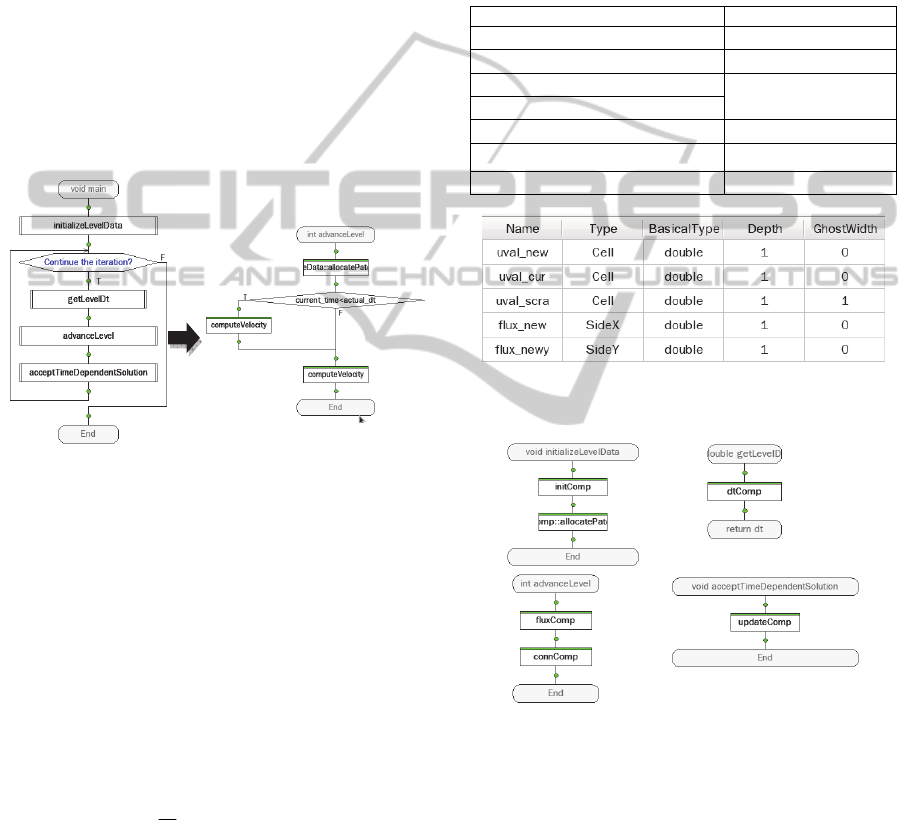
fit the need of rapid numerical integration algorithm
implementation. The main flowchart is composed of
some semi-predefined flowcharts which includes
initalizeLevelData, getLevelDt, advanceLevel and
acceptTimeDependentSolution. They are actually the
member procedures of the level strategy class. A
flowchart is semi-predefined means that the
interface of it is built-in defined and the body of it
need to be implemented by the user. In HiPro,
components are inserted into the flowchart to define
the implementation of the procedure. Loops,
conditional branches and other control structures can
be used to configure the execution logic of the
components. On the right of the Figure 7, part of
advanceLevel is illustrated, where some integrator
components are created and used to organize the
actual computation.
Figure 7: Assembling integrator components to implement
a procedure for the level strategy class.
Flowcharts and kernels as well as other data from
graphical input are stored into a database, which are
then feed into code generation engine to accomplish
automatic code generation using predefined code
templates.
4 APPLICATION
We give a test on developing a simulation program
for solving linear advection equation:
0)(
ua
t
u
The initial value is given by
)()0,(
0
xuxu
and
the boundary condition is set as
)(),( tutxu
.
The computation is decoupled into six numerical
subroutines. Six components are created to
implement parallel computing and communication.
The subroutines with category specification and
components are listed in Table 4. Generally there is
a one-to-one relationship between the subroutines
and the components. One exception is that a
subroutine of category Sub II must be assigned to a
component together with a subroutine of category
Sub I. The other exception is that a component of
Memory type must be created to allocate or
deallocate memory for physical variables.
Table 4: Subroutines and integrator components created
for the simulation.
Sequential Subroutines(Category) Component(Type)
initset(Sub I) initComp(Initialize)
getdt(Sub I) dtComp(Dt)
setphy(Sub II)
fluxComp(Numerical)
getflux(Sub I)
updateconser(Sub I)
connComp(Numerical)
acceptsolution(Sub I) updateComp(Copy)
allocComp(Memory)
Figure 8: Screenshot of physical variables created in HiPro
for solving the linear advection equation.
Figure 9: The four implemented semi-predefined
flowcharts.
Figure 8 shows the screenshot of physical
variables created in HiPro for the simulation. Four
semi-predefined flowcharts with components
inserted are shown in figure 9. As is presented in
Table 5, in this application it consists of 17 C++
program files, 2 files coded in C language, 7 Fortran
files and 1 CMake file. Among 1947 lines of source
code about 6 percent of them are coded by hand.
ICSOFT-EA2014-9thInternationalConferenceonSoftwareEngineeringandApplications
130
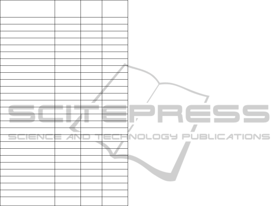
Table 5: Program files and ratio of auto-generated for the
simulation of solving linear advection equation.
Program files Language Lines
Ratio of
auto-
generated
Main.C C++ 237 100%
VariableManager.h C++ 59 100%
VariableManager.C C++ 152 100%
LinAdvLevelStrategy.h C++ 92 100%
LinAdvLevelStrategy.C C++ 99 100%
ICPInitComp.h C++ 33 100%
ICPInitComp.C C++ 58 100%
ICPDtComp.h C++ 42 100%
ICPDtComp.C C++ 90 100%
ICPFluxComp.h C++ 40 100%
ICPFluxComp.C C++ 106 100%
ICPConnComp.h C++ 40 100%
ICPConnComp.C C++ 90 100%
ICPUpdateComp.h C++ 40 100%
ICPUpdateComp.C C++ 86 100%
ICPAllocComp.h C++ 26 100%
ICPAllocComp.C C++ 35 100%
LinAdvFort.h C 33 100%
TypeDefs.h C 26 100%
typedef.f90 Fortran 29 100%
initset.f90 Fortran 42 50%
getdt.f90 Fortran 23 70%
setphy.f90 Fortran 59 50%
getflux.f90 Fortran 64 50%
updateconser.f90 Fortran 60 60%
acceptsolution.f90 Fortran 40 70%
CMakeLists.txt CMake 246 100%
5 CONCLUSIONS
Parallel programming usually involves tedious
amount of coding and often error-prone for domain
experts. HiPro-CodeGen, a powerful automatic code
generation engine, is developed to generate major
and tedious part of a JASMIN application. Plenty of
knowledge and technologies are shielded from the
programmers, including:
Object-oriented programming
C++ language
Hybrid programming with C++ and Fortran
Component-based programming
It frees users from unnecessary exposure to
complex features of programming issues of
languages and JASMIN interfaces together with the
application code organization. Users only need to
write body code for numerical kernels with well-
defined interface through GUI in Fortran which has
been used for scientific computing program
development for tens of years and is quite familiar to
them.
Practice demonstrates that non-programmers can
create fairly complex programs with little training. It
greatly reduces programming complexities and make
numerical application development easy and fast.
Real world applications show that HiPro-CodeGen
ensures high-performance and high-quality for
scientific numerical simulation.
ACKNOWLEDGEMENTS
This work is under the auspices of the National
Natural Science Foundation of China (61033009),
National Basic Key Research Special Fund
(2011CB309702) and National High Research and
Development Program of China (2012AA01A309).
REFERENCES
Benjamin A. A., Robert A.,David E. B.,etc. 2006. A
component architecture for high-performance
scientific computing. The International Journal of
High Performance Computing Applications,20(2):162-
202
Boris S.,Alexey S.,Vera I. Integrated Development
Environment for Visual parallel programming. In
Proceedings of the 10
th
Conference of Fruct
Association.
Liao L., Zhang A.Q., Yang Z., etc. IDE-JASMIN:An
Interactive Graphical Approach for Parallel
Programming in Scientific Computing. 8th
International Conference on Software Engineering
and Applications.
Mo Z.Y., Pei W.B., 2009. Scientific computing
application codes. Physics (in Chinese).
Mo Z.Y., Zhang A.Q., 2010. JASMIN: A parallel software
infrastructure for scientific computing. Front. Comput.
Sci. China.
Mo Z.Y., Zhang A.Q., 2009. User’s guide for JASMIN,
Technical Report. https://www.iapcm.ac.cn/jasmine.
Parker, S.G., 2002. A component-based architecture for
parallel multi-physics PDE simulation. In Proceedings
of the International Conference on Computational
Science-Part III. Springer-Verlag.
Pei W.B., Zhu S.P., 2009. Scientific computing in Laser
Fusion. Physics (in Chinese), 38(8): 559-568.
Tia W. 2004.The SFC Editor a graphical tool for
algorithm development. Jounal of Computing Science
in Colleges.
HiPro-CodeGen-AutomaticProgrammingforParallelNumericalSimulations
131
