
Enhanced Physical Interaction Performance for Compliant Joint
Manipulators using Proxy-based Sliding Mode Control
Navvab Kashiri
1
, Nikos G. Tsagarakis
1
,
Mich¨ael Van Damme
2
, Bram Vanderborght
2
and Darwin G. Caldwell
1
1
Department of Advanced Robotics, Istituto Italiano di Tecnologia, Genova, Italy
2
Department of Mechanical Engineering, Vrije Universiteit Brussel, Brussels, Belgium
Keywords:
Proxy-based Sliding Mode Control, Physical Human-robot Interaction, Flexible Joint Manipulators, Torque
Control, Compliant Joints, Linear-quadratic Optimal Control, Position Control, Underactuated Systems.
Abstract:
The use of typical position controllers for robots working around humans can involve some risks when
unintended physical human-robot interactions occur. In order to benefit from a proper tracking performance
during normal operations, and a smooth and damped recovery from position errors due to contacts with
external objects/agents, Proxy-based Sliding Mode Control was proposed. While the efficacy of this controller
in fully actuated manipulators was discussed, the employment of this controller in underactuated systems
has not been studied so far. This paper introduces a control scheme to implement this controller in a class
of underactuated systems. Specifically, the control of flexible joint manipulators possessing passive elastic
elements in series with motors is studied. The formulation of Proxy-based Sliding Mode Control is adopted
according to the stability requirements of this type of dynamic systems, and a torque controller required for
the regulation of the the output torque of actuation units is designed using the Feedback Linearization and
the Linear Quadratic optimal control approach. The performance of the proposed scheme is demonstrated in
dynamic simulation of an anthropomorphic compliant arm.
1 INTRODUCTION
The employment of robots for different purposes
and in various environments has attracted the
growing attention of researchers during the last
decade. The extension of robotic applications
beyond industrial environment requires robots
with intrinsic characteristics respecting the
prerequisites of tasks. However, traditional robots
are typically driven by actuators comprised of
position/velocity control systems with large gains
and high reduction transmission units which are quite
stiff and non-back-drivable. The output mechanical
impedance of robots driven by such actuation units
will be very high due to large reflected inertia of
drives and the rigidity of transmission elements. The
performance of these robots is therefore limited in
terms of mechanical robustness, and flexibility in
respecting the requirements of different tasks such as
interactions with external agents and objects. Hence,
the development of new actuation units for robotic
systems has been widely explored.
The incorporation of passive elastic elements
into the transmission system of traditional actuators
was proposed to suppress difficulties brought by
stiff actuation systems (Tsagarakis et al., 2009).
Adding flexibility to drive units reduces the output
impedance, amplifies the robustness, and enhances
the performance of the robot when it operates in
unstructured environments and when it interacts with
humans (Bicchi et al., 2001). The passive elasticity
can amplify the peak output torque (Paluska and Herr,
2006; Mathijssen et al., 2013) which can be also
exploited for explosive motions (Chen et al., 2013a;
Braun et al., 2013).
The incorporation of passive elastic elements into
the actuation units, however, increases the complexity
of the system, thereby sophisticating the control
scheme required for achieving a suitable tracking
performance. Hence, the control of flexible joint
robots has been widely studied (Ozgoli and Taghirad,
2006; Chen et al., 2013b), although a majority of
these methods are highly model-based and/or requires
high order derivatives resulting in implementation
175
Kashiri N., Tsagarakis N., Van Damme M., Vanderborght B. and Caldwell D..
Enhanced Physical Interaction Performance for Compliant Joint Manipulators using Proxy-based Sliding Mode Control.
DOI: 10.5220/0005063201750183
In Proceedings of the 11th International Conference on Informatics in Control, Automation and Robotics (ICINCO-2014), pages 175-183
ISBN: 978-989-758-040-6
Copyright
c
2014 SCITEPRESS (Science and Technology Publications, Lda.)
difficulties. These issues motivated roboticists to
develop variable impedance actuators (Vanderborght
et al., 2013) which can be typically considered in
two categories: variable stiffness actuators (Catalano
et al., 2011; Tsagarakis et al., 2011; Vanderborght
et al., 2011), and variable damping actuators (Garcia
et al., 2011; Laffranchi et al., 2011; Radulescu et al.,
2012).
A stable Proportional-Derivative (PD) based
controller plus off-line gravity compensation for
flexible joint manipulators was developed in (Tomei,
1991). The controller is relied upon the control of
desired motor position derived from the static motion
equations of links. An improvement to this approach
was proposed in (De Luca et al., 2005) by means
of the on-line compensation of gravity through a
‘gravity-biased’ modification of the motor position
feedback. A novel approach for the control of such
dynamic systems was proposed in (Albu-Sch¨affer
et al., 2012) that comes from the idea of controlling an
equivalent link position that approaches to the actual
state, and also compensating the gravitational torque
using the equivalent state.
In the way towards a safer and friendly
human-robot interaction (Bicchi et al., 2001),
Proxy-based Sliding Model Control (PSMC)
approach was introduced in (Kikuuwe and Fujimoto,
2006), which was employed for a pneumatic actuated
arm in (Van Damme et al., 2009; Beyl et al., 2009)
and an electro-pneumatic powered platform in (Prieto
et al., 2013). In (Kikuuwe et al., 2010), this control
approach was elaborated as a safer extension to the
conventional Proportional-Integral-Derivative (PID)
controller, and the corresponding stability proof was
shown. The performance of this efficacious approach
was presented for fully actuated manipulators;
however the employment of this method for passively
actuated manipulators has not been discussed so far.
This paper studies the PSMC approach for flexible
joint manipulators. The control scheme is developed
in joint space as it was shown that this controller
achieves a quite higher tracking performance when
implemented in joint space rather than that in task
space (Van Damme et al., 2009). The dynamic
equations of this class of underactuated systems is
first introduced. A position control approach for this
class of dynamic systems (Albu-Sch¨affer et al., 2012)
is presented, and the PSMC approach formulation
is adopted according to stability considerations in
passively actuated manipulators. A novel torque
controller required for the implementation of the
PSMC scheme is also designed based on the
Feedback Linearization approach and the use of
the Linear Quadratic (LQ) optimal method. The
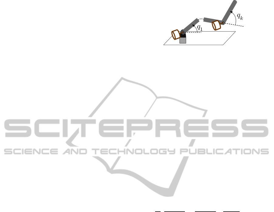
Figure 1: Schematic of a k−link serial manipulator.
performance of proposed scheme is evaluated in
dynamic simulations of a flexible joint arm.
The rest of this paper is structured as follows:
the dynamic modeling of aforesaid manipulators is
presented in Section 2. The control scheme including
position control, PSMC and torque control are
discussed in Section 3. The description of simulated
manipulator and simulation results presenting the
validity of proposed scheme are introduced in Section
4. Finally, section VI addresses the conclusion and
future works.
2 DYNAMIC MODELING
Given a k−link serial manipulator, shown in Fig. 1,
the dynamic equations of this nonlinear system can be
described using Euler-Lagrange method as (Ortega,
1998)
d
dt
(
∂L(x, ˙x)
∂˙x
) −
∂L(x, ˙x)
∂x
+
∂F (˙x)
∂x
= u, (1)
where x ∈ ℜ
n
shows the vector of generalized
coordinates (n ≥ k), u ∈ ℜ
n
is the vector of
generalized control input torques, F is the Rayleigh
dissipation function, and L(x, ˙x) symbolizes the
Lagrangian function which is defined by
L(x, ˙x) = T (x, ˙x) − U(x), (2)
where T (x, ˙x) shows the kinetic energy function and
U(x) is the potential energy function.
Manipulator fully powered by compliant actuators
possess as many passive degrees of freedom (DOFs)
(link positions q = [q
1
, .., q
k
]) as active ones (motor
positions θ = [θ
1
, .., θ
k
]), i.e. n = 2k. Fig. 2
demonstrates the mechanical model of an actuation
unit of such systems. Having defined the vector
of generalized coordinates as x = [q, θ], the control
input vector is presented by u = [0, τ
m
] in which
τ
m
= [τ
m,1
, .., τ
m,k
] is the vector of motor torques.
The dynamic equations of the system is therefore
expressed by
M(q)¨q+ c(q, ˙q) + g(q) = τ
t
(φ,
˙
φ), (3)
ICINCO2014-11thInternationalConferenceonInformaticsinControl,AutomationandRobotics
176
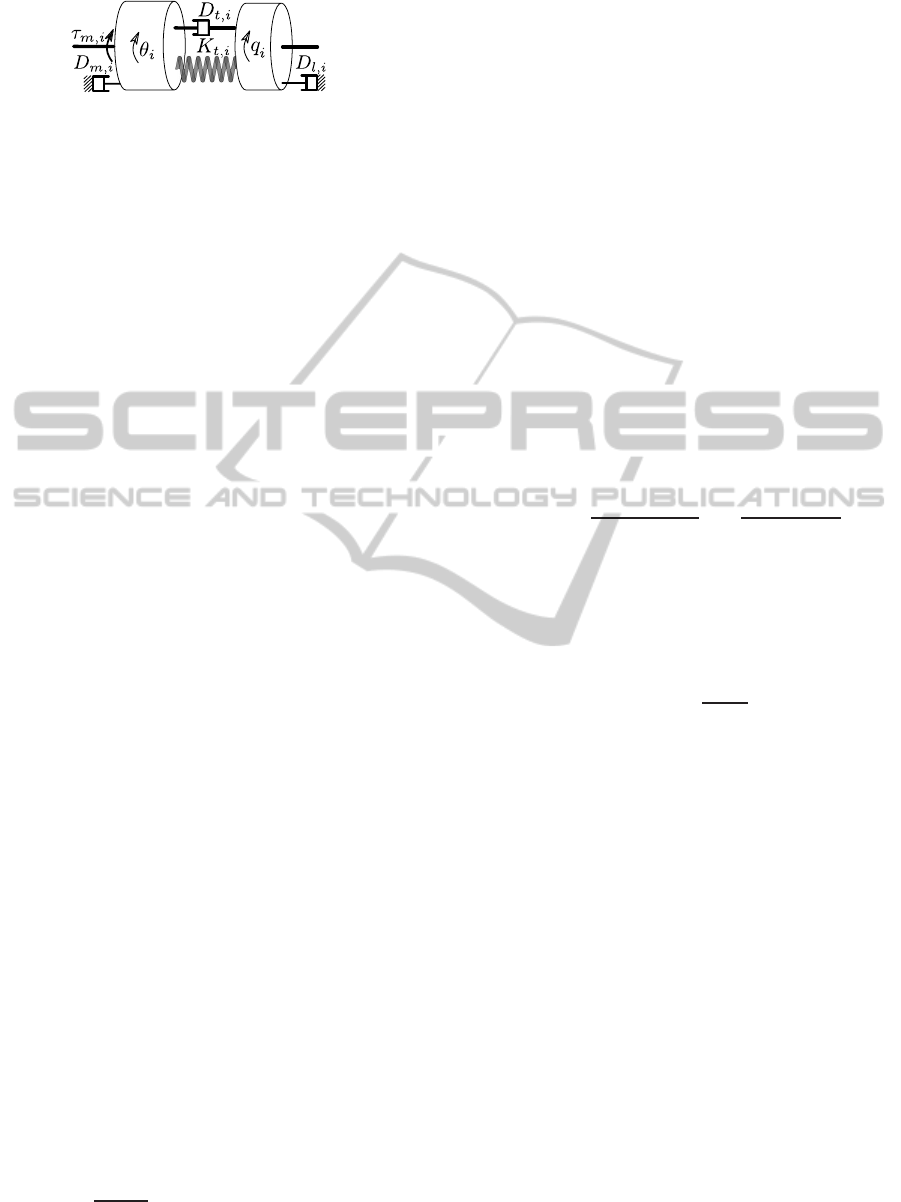
Figure 2: Mechanical model of i−th series viscoelastic
actuator.
B
¨
θ + D
m
˙
θ + τ
t
(φ,
˙
φ) = τ
m
, (4)
τ
t
(φ,
˙
φ) = K
t
φ + D
t
˙
φ, (5)
where φ = θ − q is the vector of transmission
displacements; B = diag(B
1
, ..., B
k
) is the inertia
matrix of motors; M(q) ∈ ℜ
k×k
is the inertia
matrix of links; c(q, ˙q) ∈ ℜ
k
denotes the vector
of Coriolis/centrifugal terms of links; g(q) ∈ ℜ
k
denotes the gravitational torque of links; D
m
=
diag(D
m,1
, ..., D
m,k
) presents the damping matrix
associated with motors; τ
t
= [τ
t,1
, .., τ
t,k
] is the vector
of transmission torques applied by passive elements
embedded in series with motors, with the constant
stiffness of K
t
= diag(K
t,1
, ..., K
t,k
) and damping of
D
t
= diag(D
t,1
, ..., D
t,k
).
3 CONTROL
The generic control task is the regulation of actuator
torques of the manipulator τ
m
in such a way that
the position of links q tracks a desired position q
d
=
[q
d,1
, .., q
d,k
] while large positional errors are damped
smoothly. First, the conventional position control of
SEA-based manipulators is discussed.
3.1 Position Control
The position control of fully actuated manipulators
can be done using a PID controller based on the
error between the desired link position and the actual
one, i.e. e = q
d
− q. It is principally feasible as
it is a collocated feedback measured from the same
DOF as the corresponding actuator. However, link
positions are non-collocated feedbacks in flexible
joint manipulators, and the control of these states
in this way can cause instabilities (Cannon and
Rosenthal, 1984). Hence, the stable link position
control of flexible joint robots has been widely
studied. A majority of these methods defines a set
point according to the dynamic equations of links in
static form
∂U(x)
∂q
= g(q) − K
t
φ = 0. (6)
The most conventional method for the definition
of control set point was introduced in (Tomei, 1991).
This method is based on deriving the desired motor
positions from the desired link positions using (6),
i.e. θ
d
= q
d
+ K
−1
t
g(q
d
), and controlling these states
using the corresponding collocated feedback θ, in
addition to the compensation of the gravitational
torque using a feedforward term. A more recent
method suggested in (Albu-Sch¨affer et al., 2012)
exploits the static link equations (6) to extract an
equivalent value for the non-collocated states (link
positions q) using the collocated feedbacks (motor
positions θ). For any given motor position θ, the
equivalent link position ¯q is numerically obtained
by solving (6), which was proved to have a unique
solution due to the convex nature of potential
energy function. Here, the Newton-Raphson method
(Ben-Israel, 1966) is employed to solve (6). The
equivalent link position ¯q is therefore iteratively
computed from
¯q
j
= ¯q
j−1
−
∂
2
U(¯q
j−1
, θ)
∂q
2
!
−1
∂U(¯q
j−1
, θ)
∂q
(7)
= ¯q
j−1
− J
−1
U
(¯q
j−1
)
g(¯q
j−1
) − K
t
θ − ¯q
j−1
,
where j = 1, .., r is the iteration index, and J
U
∈
ℜ
n×n
denotes the passive stiffness of links which is
obtained from
J
U
(q) = K
t
+
∂g(q)
∂q
. (8)
Having the equivalent link position calculated
after r−th iteration, i.e. ¯q = ¯q
r
, its derivative can be
also derived from
˙
¯q = J
−1
U
(¯q)K
t
˙
θ. (9)
Using the equivalent of link position instead of the
direct feedback, the potential instability issues caused
by the non-collocated feedback is avoided as the
equivalent value is obtained only from the collocated
motor position feedback. Having employed this
equivalent feedback, the proxy-based sliding mode
position controller is presented below to derive the
torque required to be applied on the manipulator links
through the transmission systems.
3.2 Proxy-based Sliding Mode Control
As an extension to conventional Sliding mode and
PID control methods, Proxy-based Sliding Mode
Control method was introduced in (Kikuuwe et al.,
2010) by exploiting the concepts of ‘Proxy’ and
‘Virtual’ Coupling from the haptic area. Fig. 3
EnhancedPhysicalInteractionPerformanceforCompliantJointManipulatorsusingProxy-basedSlidingModeControl
177
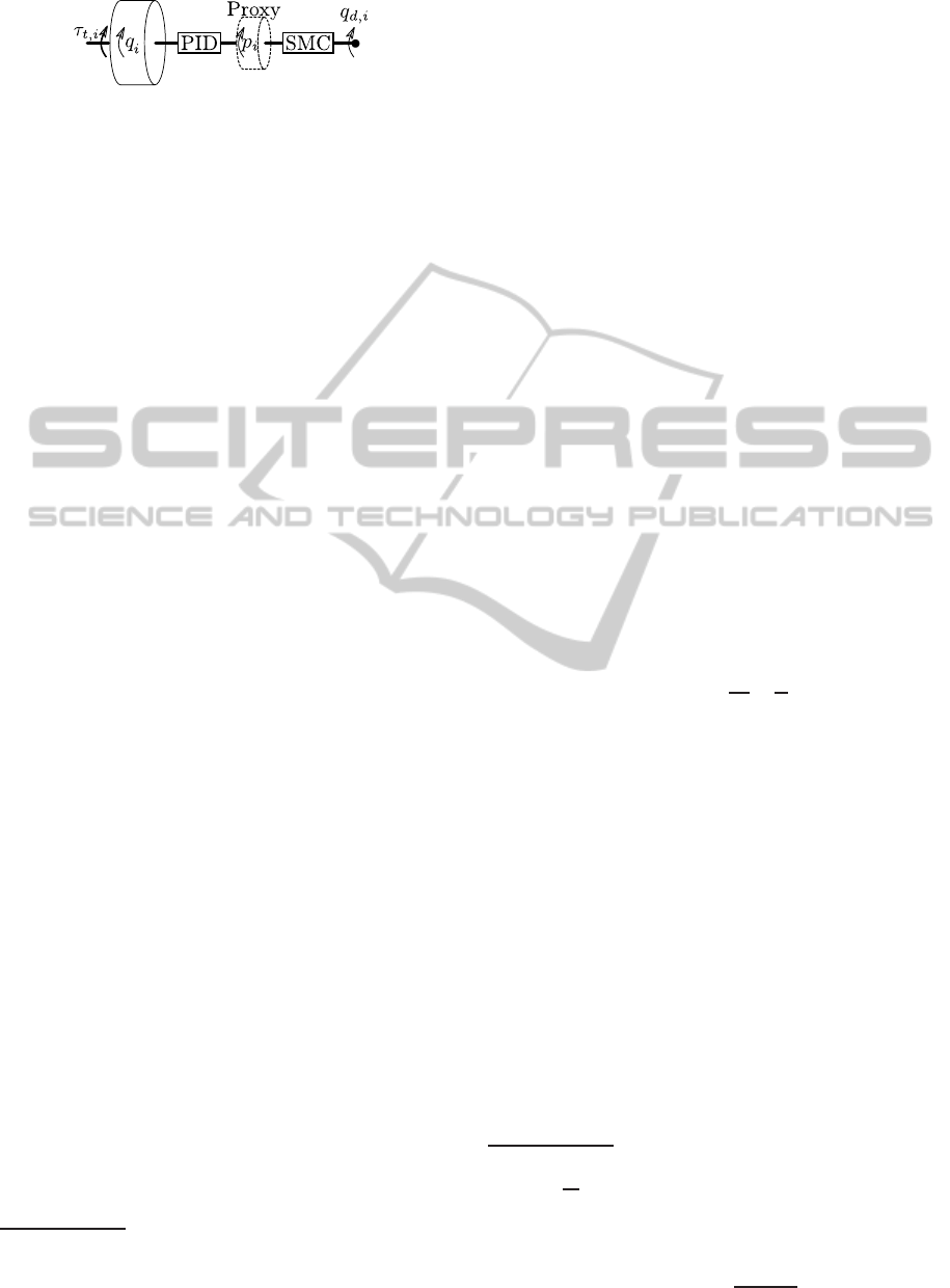
Figure 3: Physical interpretation of PSMC.
describes the physical idea behind this control
approach. It is based on the connection of a virtual
object, called proxy, to the output link by means
of a virtual coupling that is implemented through a
PID controller to maintain the link attached to the
proxy; and the position of proxy is controlled using
a Sliding Mode Controller (SMC) to track the desired
link position. The fundamental benefit taken from this
controller is the isolation of the ‘local’ and ‘global’
dynamics. While the local dynamics, i.e. the response
to small position errors, is defined through the virtual
coupling, the global dynamics, i.e the response to
large position errors, is specified by the sliding mode
controller. The PSMC approach can then provide
an accurate tracking during normal operations with
smooth recovery from large position errors resulting
from undesigned interactions
1
. The proxy receives
the torque from both the SMC controller and the
virtual PID coupling, and the latter is defined as the
reference torque τ
r
∈ ℜ
k
to be exerted to the link
through the motor.
By defining p = [p
1
, .., p
k
] as the vector of proxy
positions, the torque τ
PID
∈ ℜ
k
from the PID coupling
is determined by
τ
PID
= K
P
˙a+ K
I
a+ K
D
¨a, (10)
where K
P
, K
I
and K
D
∈ ℜ
k×k
are diagonal positive
definite matrices representing proportional, integral
and derivative gains of virtual coupling, respectively,
and a is the integral of the virtual coupling error.
While this error was defined based on the link position
for fully actuated manipulators, the equivalent link
position ¯q is used here for flexible joint robots. It is
then specified by
a =
Z
(p− ¯q)dt. (11)
The torque τ
SMC
∈ ℜ
k
produced by the sliding
mode controller, which is exploited for the control of
proxy, is defined as follows
τ
SMC
= Γsgn(s), (12)
where Γ ∈ ℜ
k×k
is a diagonal matrix defining the
torque limit of joints, sgn(.) symbolizes the Signum
1
This problem can be also solved using motion planning
provided that the system can sense ‘unforeseen’ events,
however the sensory information is not usually available.
function
2
acting on individual elements of the vector,
and the sliding manifold s ∈ ℜ
k
is
s = (q
d
− p) + Λ(˙q
d
− ˙p), (13)
where Λ = diag(λ
1
, .., λ
k
) is a positive definite matrix
specifying the time constant of the sliding surface of
joints.
By introducing the auxiliary vector σ as
σ = (q
d
− ¯q) + Λ(˙q
d
−
˙
¯q), (14)
the SMC torque τ
SMC
from (12) can be rewritten as
τ
SMC
= Γsgn(σ − ˙a− Λ ¨a). (15)
By setting the proxy mass to zero (Kikuuwe
and Fujimoto, 2006), the dynamics of the proxy
expresses the equality of torques from the SMC and
the virtual PID coupling; and since the latter specifies
the reference torque τ
r
, it can be expressed using (10)
and (15) as follows
τ
r
= τ
PID
= τ
SMC
(16)
= K
P
˙a+ K
I
a+ K
D
¨a
= Γsgn(ψ − Λ ¨a),
where ψ = σ − ˙a is an auxiliary vector. With
considering the mathematical relation
3
δ = β+ γsgn(ρ − κδ) (17)
= β+ γsat
ρ
κγ
−
β
γ
,
where δ, β, γ, ρ and κ are arbitrary variables, and
sat(.) symbolizes the Saturation function
4
, (16) can
be solved for ¨a as follows
¨a =− K
−1
D
(K
P
˙a+ K
I
a)+ (18)
K
−1
D
Γsat
Γ
−1
K
D
Λ
−1
ψ + K
P
˙a+ K
I
a
,
in which the saturation function acts on individual
elements of the given vector. By adding the gravity
compensation feed-forward torque, the reference
torque can therefore be obtained from
τ
r
= Γsat
Γ
−1
K
D
Λ
−1
ψ + K
P
˙a+ K
I
a
+ g(¯q).
(19)
In order to execute the proxy-based sliding mode
position controller, the above torque needs to be
exerted to links. Hence, a torque controller is
employed, which is expressed as follows.
2
The Signum of an arbitrary variable ξ is defined as
sgn(ξ) =
ξ
|ξ|
which is undefined at ξ = 0.
3
This relation can be simply proved from δ = sgn(ρ −
δ) ⇔ δ = sat(ρ).
4
The Saturation or Clipping function of an arbitrary
variable ξ is defined as sat(ξ) =
ξ
max(1,|ξ|)
.
ICINCO2014-11thInternationalConferenceonInformaticsinControl,AutomationandRobotics
178

3.3 Torque Control
A torque controller is designed in this section in order
to track the reference torque given by the Proxy-based
Sliding Mode Controller. (Vertechy et al., 2010)
studied a torque control approach for single flexible
joints based on the Linear-Quadratic optimal method,
and presented the tracking performance achieved
by the proposed scheme in comparison with other
approaches. A similar approach extended for flexible
joint manipulators is presented in this work.
By subtracting the angular acceleration of motors
¨q from that of links
¨
θ, using (3)-(5), it can be shown
that
¨
φ + B
−1
D
m
˙
θ − M
−1
(q)g(q) (20)
+
B
−1
+ M
−1
(q)
(K
t
φ + D
t
˙
φ) = B
−1
τ
0
,
where τ
0
∈ ℜ
k
is the motor torque associated with the
system dynamics when the Coriolis/centrifugal terms
are not considered. It is neglected on the basis that the
system is meant for human-robot interaction and the
fast motion of links is strictly avoided due to safety
requirements (Haddadin et al., 2009). Defining the
Feedback Linearization controller as
τ
0
= BM
−1
(q)
K
t
φ + D
t
˙
φ − g(q)
+ D
m
˙
θ + Bv,
(21)
the dynamic equation of the transmission (20) is
rewritten as
¨
φ +
ˇ
K
t
φ +
ˇ
D
t
˙
φ = v, (22)
where v ∈ ℜ
k
is the new control input for the linear
dynamic system (22),
ˇ
K
t
= B
−1
K
t
and
ˇ
D
t
= B
−1
D
t
.
The control problem is then to design v ∈ ℜ
k
in a way that the transmission torque τ
t
tracks the
reference value τ
r
given by the PSMC. By defining
a new state vector w = [φ,
˙
φ] ∈ ℜ
2k
, the linear system
(22) can be expressed in state-space form as follows
˙w = Aw+ Fv
τ
t
= Cw
, (23)
where A = [[0
k×k
, −
ˇ
K
t
]
T
, [I
k
, −
ˇ
D
t
]
T
] ∈ ℜ
2k×2k
is the
state matrix in which 0
k×k
and I
k
symbolize the zero
and the identity matrices with the dimension of k× k,
F = [0
k×k
, I
k
]
T
∈ ℜ
2k×k
is the input matrix, and C =
[K
t
, D
t
] ∈ ℜ
k×2k
is the output matrix. The control law
is chosen as (Astr¨om and Murray, 2010)
v = v
f f
+ v
fb
, (24)
where v
f f
∈ ℜ
k
and v
fb
∈ ℜ
k
are the feedforward and
feedback part of the controller. The feedforward term
does not change the stability of the system, although
it can affect the steady-space solution. This term is
then derived by setting the desired output value to the
steady state output for the close-loop system. Given a
constant torque reference, this is defined by
v
f f
= B
−1
τ
r
. (25)
The feedback term is designed using a LQ optimal
controller based on the described system augmented
with the integral of the tracking error which is defined
by
˜τ
I
=
Z
(τ
r
− τ
t
)dt. (26)
The augmented system can then be described by
˙
¯w =
¯
A¯w+
¯
Fv− Hτ
r
τ
t
=
¯
C¯w
, (27)
where
¯
A = [[A
T
, −C
T
]
T
, [0
k×3k
]
T
] ∈ ℜ
3k×3k
, ¯w =
[w, ˜τ
I
] ∈ ℜ
3k
,
¯
F = [F
T
, 0
k×k
]
T
∈ ℜ
3k×k
and H =
[0
k×2k
, I
k
]
T
∈ ℜ
3k×k
. The feedback control law is then
defined by
v
fb
= −K
LQ
¯w. (28)
where K
LQ
∈ ℜ
3k×3k
is the gain matrix designed using
the LQ optimal method. It is based on finding the
control feedback v
fb
that minimizes the performance
index J
LQ
which is expressed by
J
LQ
=
Z
∞
0
e
2µt
¯w
T
(t)Q ¯w(t) + v
T
fb
(t)Rv
fb
(t)
dt
(29)
where Q ∈ ℜ
3k×3k
and R ∈ ℜ
k×k
are positive definite
matrices defining the weights of states and the
feedback control inputs, respectively; and µ > 0 is a
constant specifying the degree of stability. By finding
the matrix P ∈ ℜ
3k×3k
from the algebraic Riccati
equation
¯
A
T
P+ P
¯
A+ 2µP+ Q = P
¯
FR
−1
¯
F
T
P, (30)
the gain matrix is obtained as K
LQ
= R
−1
¯
F
T
P. Due
to decoupling characteristic of the linear dynamic
system (22), it can be shown that the gain K
LQ
is a
diagonal matrix and it can be expressed as K
LQ
=
diag(K
φ
, K
˙
φ
, K
˜τ
I
) in which K
φ
, K
˙
φ
and K
˜τ
I
∈ ℜ
k×k
are auxiliary diagonal matrices corresponding to φ,
˙
φ
and ˜τ
I
, respectively.
By adding the active damping D
a
∈ ℜ
k×k
on
the motion of motor, and using the equivalent link
position instead of the actual one in order to avoid
using the non-collocated feedback, the overall torque
control law can accordingly be expressed by
τ
m
=τ
r
+ (D
m
− D
a
)
˙
θ − BK
˜τ
I
˜τ
I
+ (31)
BM
−1
(¯q)
K
t
φ + D
t
˙
φ − g(¯q)
− BK
φ
φ − BK
˙
φ
˙
φ,
in which τ
r
is the reference torque givenby the PSMC
approach (19).
EnhancedPhysicalInteractionPerformanceforCompliantJointManipulatorsusingProxy-basedSlidingModeControl
179
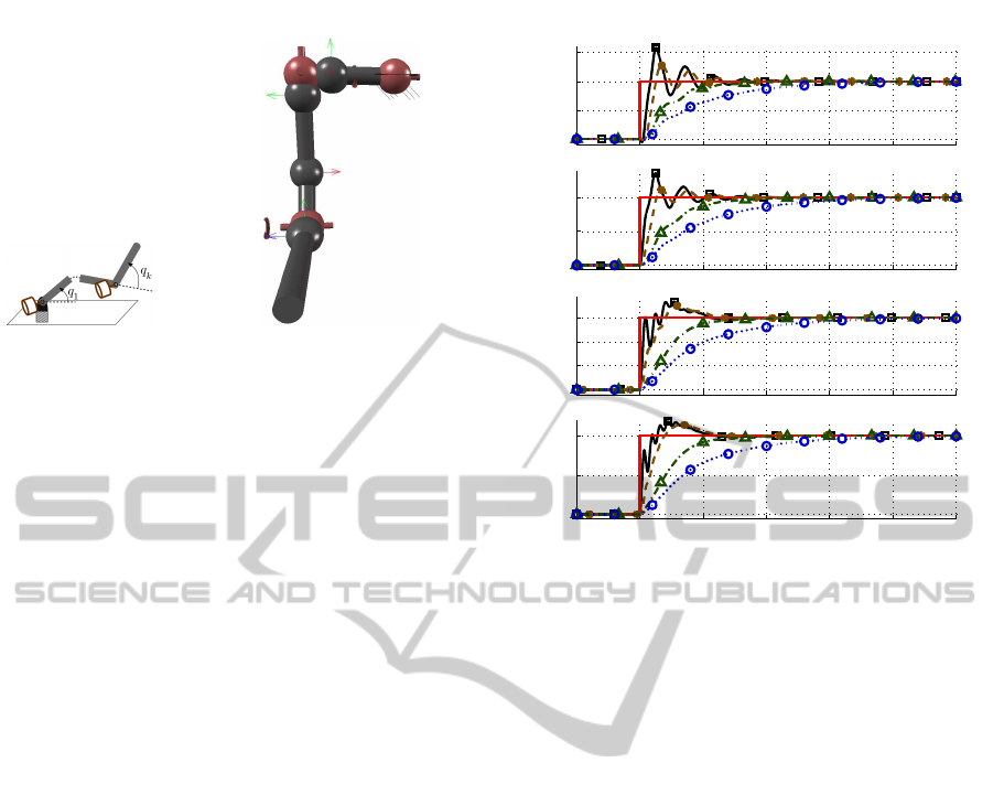
(a) (b)
Figure 4: The arm employed for simulations (a) the real
hardware (b) MapleSim model.
4 SIMULATIONS
4.1 System Description
The manipulator simulated to evaluate the
performance of presented approach is an
anthropomorphic arm introduced in (Laffranchi
et al., 2013; Kashiri et al., 2013a), powered by
compliant actuators benefiting from variable physical
damping in parallel with series elasticity (Laffranchi
et al., 2011), see Fig. 2. The physical damping of this
system is generated using a clutch mechanism driven
by a set of four piezo-electric actuators. Having
controlled the clutch force (Lee et al., 2014), a target
viscous damping behavior can be replicated (Kashiri
et al., 2014a), or a mechanical fuse can be executed
to provide both accuracy and safety (Kashiri et al.,
2014b). An image of the real manipulator beside that
of the MapleSim model employed for simulations
is illustrated in Fig. 4. The stiffness of joints are
specified using the approach proposed in (Kashiri
et al., 2013b); setting that of first two joints to 188
N.m/rad, and that of last two joints to 103 N.m/rad.
4.2 Simulation Results
In this section, the performance of the presented
control scheme is demonstrated in two simulations
in comparison with the PD controller proposed in
(Albu-Sch¨affer et al., 2012). The PID control gains of
PSMC are chosen as K
P
= diag(200, 200, 100, 100)
and K
D
= diag(50, 50, 20, 20) while the position
integrator is not considered, i.e. K
I
= diag(0, 0, 0, 0),
to present a plausible comparison with the aforesaid
existing method. The torque controller gains
K
LQ
are obtained based on the choice of Q =
diag(10
3
K
t
, 10
2
D
t
, 10I
4
), R = I
4
and µ = 1. The
0 1 2 3 4 5 6
0
0.05
0.1
0.15
q
1
[rad]
0 1 2 3 4 5 6
0
0.1
0.2
q
2
[rad]
0 1 2 3 4 5 6
0
0.1
0.2
0.3
q
3
[rad]
0 1 2 3 4 5 6
0
0.2
0.4
q
4
[rad]
t [s]
Figure 5: Step response of the system with different values
of the time constant: λ = 0.1 in (
—∗), λ = 0.5 in (-.-△),
λ = 1.0 is in (
---). The reference position is in red line
(
—), and the response of the system using the PD controller
is in (
—).
active damping of the torque controller is also
selected as D
a
= diag(20, 20, 10, 10). The homing
position of the arm at rest (zero velocity) is considered
as the initial state of the system.
4.2.1 Step Response
The first simulation presents the step response of
the manipulator when it is controlled using the
PSMC, and it is compared with the PD controller.
This test was carried out considering different time
constant values of Λ = λI
4
with λ = 0.1, λ = 0.5
and λ = 1 to present the effect of the sliding mode
parameter on the response of the system. Fig. 5
demonstrates changes in link positions versus time.
The improvement achieved by the PSMC scheme in
compared to PD controller can be clearly seen as the
system tracks the desired position with a smooth and
over-damped behavior. It can be seen that the growth
of the factor λ amplifies the damping behavior of
the system, although it also reduces the settling time
of the system. Hence, the maximum value of this
factor should be specified according to the minimum
bandwidth required for the response of the system.
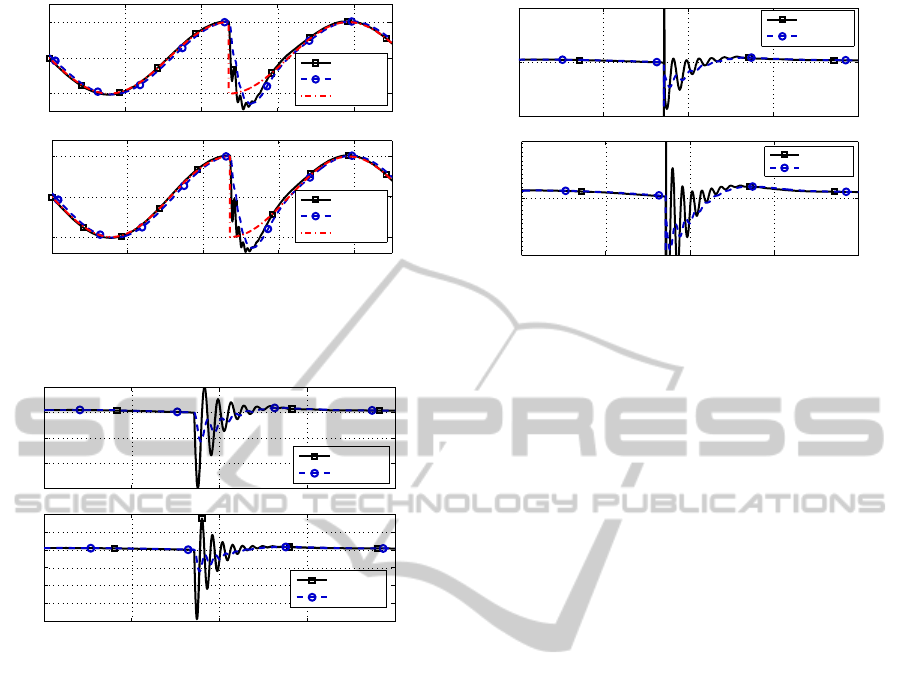
4.2.2 Sinusoidal Trajectory Tracking
This simulation is carried out to show the tracking
performance achieved by the controller. The
ICINCO2014-11thInternationalConferenceonInformaticsinControl,AutomationandRobotics
180
0 2 4 6 8
−0.1
0
0.1
q
3
[rad]
0 2 4 6 8
−0.2
0
0.2
q
4
[rad]
t [s]
PD
PSMC
q
d,3
PD
PSMC
q
d,4
Figure 6: Time history of link positions; desired values in
compared to actual ones when the system is controlled by
PSMC and PD.
3 4 5 6 7
−3
−2
−1
0
1
˙q
3
[rad/s]
3 4 5 6 7
−8
−6
−4
−2
0
2
4
˙q
4
[rad/s]
t [s]
PD
PSMC
PD
PSMC
Figure 7: Time history of link velocities when the system is
controlled by PSMC in compared to that by PD.
task considered for this simulation is to track a
sinusoidal reference in elbow joints (i = 3, 4) while
a discontinuity in desired position is imposed in
order to evaluate the response of the system to large
positional errors. For the sake of clarity, only a time
constant of λ = 0.1 is considered for this simulation.
Fig. 6 illustrates changes in link positions versus
time when the systems is controlled by PSMC in
compared to that by PD. It can be seen that the PSMC
approach represents a tracking performance quite
similar to the conventional PD controller when the
reference trajectory is continuousand smooth, and the
use of PSMC hardly affect the control performance;
however, in the case of unforeseen events leading to
a large positional discontinuity, the conventional PD
controller shows considerable oscillations while the
PSMC recovers smoothly, although the increase of
the time constant λ can amplify the damping behavior
achieved by the PSMC (as shown in previous
simulation). The difference in performance of these
controllers can be seen more clearly in link velocities
and motor torques which are illustrated in Fig. 7 and
Fig. 8, respectively. When the reference position
3 4 5 6 7
−50
0
50
τ
m,3
[N.m]
3 4 5 6 7
−50
0
50
τ
m,4
[N.m]
t [s]
PD
PSMC
PD
PSMC
Figure 8: Time history of motor torques when the system is
controlled by PSMC in compared to that by PD.
changes smoothly, change in the motor torques and
the link velocities resulting from both controllers are
also quite smooth and reasonable. However, large
positional errors (shown in Fig. 6 at t = 2.7s) in a
torque-limited PD controller result in very high motor
torques with substantial changes leading to significant
oscillations in link velocities; while the employment
of the PSMC moves the proxy in such a way that the
target position of the PSMC’s PD controller moves
gently. This provides a plausible change in motor
torques and a smooth damping of the link motion.
It should be noted that the increase of the derivative
action, i.e. D-gains of the PID controller, would
theoretically replicate the same behavior; however
it is not practically feasible due to typical noise in
velocity feedbacks.
5 CONCLUSIONS
In the trend towards friendly human-robotinteraction,
Proxy-based Sliding Model Control approach was
introduced to maintain proper tracking performance
in normal operations while showing a smooth and
safe response to undesigned interactions. However,
the study of this approach for flexible joint robots
had not been discussed. This paper proposed a
control scheme to exploit this method for this class
of underactuated systems. The PSMC approach
formulation was adopted according to stability
requirements of flexible joint manipulators; and
in order to implement this controller on flexible
joint robots, a novel torque controller based on
the Feedback Linearization approach and the Linear
Quadratic Optimal control method was presented.
Finally, the performance of the proposed scheme was
demonstrated in dynamic simulations of a flexible
joint manipulator to represent the improvement
EnhancedPhysicalInteractionPerformanceforCompliantJointManipulatorsusingProxy-basedSlidingModeControl
181

achieved by this controller in compared to a
conventional PID approach. The future work of
the authors will include the implementation of the
proposed approach on the real arm to validate the
performance of this scheme in experimental results.
ACKNOWLEDGEMENTS
This work is supported by the European Research
Council under EU FP7-ICT projects SAPHARI no.
287513 and WALKMAN no. 611832.
REFERENCES
Albu-Sch¨affer, A., Petit, F., and Ott, C. (2012). Energy
Shaping Control for a Class of Underactuated
Euler-Lagrange Systems. In Petrovic, I. and Korondi,
P., editors, 10th IFAC Symposium on Robot Control,
Dubrovnik, Croatia.
Astr¨om, K. J. and Murray, R. M. (2010). Feedback systems:
an introduction for scientists and engineers. Princeton
university press.
Ben-Israel, A. (1966). A Newton-Raphson method for
the solution of systems of equations. Journal
of Mathematical analysis and applications,
15(2):243–252.
Beyl, P., Van Damme, M., Van Ham, R., Vanderborght, B.,
and Lefeber, D. (2009). Design and control of a lower
limb exoskeleton for robot-assisted gait training.
Applied Bionics and Biomechanics, 6(2):229–243.
Bicchi, A., Rizzini, S. L., and Tonietti, G. (2001).
Compliant design for intrinsic safety: General issues
and preliminary design. In Intelligent Robots
and Systems, 2001. Proceedings. 2001 IEEE/RSJ
International Conference on, volume 4, pages
1864–1869. IEEE.
Braun, D. J., Petit, F., Huber, F., Haddadin, S., Van
Der Smagt, P., Albu-Schaffer, A., and Vijayakumar,
S. (2013). Robots driven by compliant actuators:
Optimal control under actuation constraints. IEEE
Transactions on Robotics, 29(5):1085–1101.
Cannon, R. H. and Rosenthal, D. E. (1984). Experiments
in control of flexible structures with noncolocated
sensors and actuators. Journal of Guidance, Control,
and Dynamics, 7(5):546–553.
Catalano, M. G., Grioli, G., Garabini, M., Bonomo,
F., Mancini, M., Tsagarakis, N., and Bicchi, A.
(2011). VSA-CubeBot: A modular variable stiffness
platform for multiple degrees of freedom robots.
In Proceedings - IEEE International Conference on
Robotics and Automation, pages 5090–5095.
Chen, L., Garabini, M., Laffranchi, M., Kashiri, N.,
Tsagarakis, N. G., Bicchi, A., and Caldwell, D. G.
(2013a). Optimal Control for Maximizing Velocity
of the CompAct Compliant Actuator. In Robotics
and Automation (ICRA), 2013 IEEE International
Conference on, pages 516–522, Karlsruhe (Germany).
Chen, L., Laffranchi, M., Lee, J., Kashiri, N., Tsagarakis,
N. G., and Caldwell, D. G. (2013b). Link
position control of a compliant actuator with unknown
transmission friction torque. In Intelligent Robots
and Systems (IROS), 2013 IEEE/RSJ International
Conference on, pages 4058–4064. IEEE.
De Luca, A., Siciliano, B., and Zollo, L. (2005). PD control
with on-line gravity compensation for robots with
elastic joints: Theory and experiments. Automatica,
41(10):1809–1819.
Garcia, E., Ar´evalo, J. C., Mu˜noz, G., and Gonzalez-de
Santos, P. (2011). Combining series elastic actuation
and magneto-rheological damping for the control of
agile locomotion. Robotics and Autonomous Systems,
59(10):827–839.
Haddadin, S., Albu-Sch¨affer, A., and Hirzinger, G. (2009).
Requirements for safe robots: Measurements, analysis
and new insights. The International Journal of
Robotics Research, 28(11-12):1507–1527.
Kashiri, N., Laffranchi, M., Lee, J., Tsagarakis, N. G.,
Chen, L., and Caldwell, D. (2014a). Real-time
damping estimation for variable impedance actuator.
In Robotics and Automation (ICRA), 2014 IEEE
International Conference on, pages 1072–1077.
IEEE.
Kashiri, N., Laffranchi, M., Tsagarakis, N. G., Margan, A.,
and Caldwell, D. G. (2014b). Physical Interaction
Detection and Control of Compliant Manipulators
Equipped with Friction Clutches. In Robotics
and Automation (ICRA), 2014 IEEE International
Conference on, pages 1066–1071. IEEE.
Kashiri, N., Laffranchi, M., Tsagarakis, N. G., Sardellitti,
I., and Caldwell, D. G. (2013a). Dynamic
modeling and adaptable control of the CompAct arm.
In Mechatronics (ICM), 2013 IEEE International
Conference on, pages 477–482.
Kashiri, N., Tsagarakis, N. G., Laffranchi, M., and
Caldwell, D. G. (2013b). On the stiffness design
of intrinsic compliant manipulators. In Advanced
Intelligent Mechatronics (AIM), 2013 IEEE/ASME
International Conference on, pages 1306–1311.
IEEE.
Kikuuwe, R. and Fujimoto, H. (2006). Proxy-based sliding
mode control for accurate and safe position control.
In Robotics and Automation, 2006. ICRA 2006.
Proceedings 2006 IEEE International Conference on,
pages 25–30. IEEE.
Kikuuwe, R., Yasukouchi, S., Fujimoto, H., and Yamamoto,
M. (2010). Proxy-based sliding mode control: a safer
extension of PID position control. Robotics, IEEE
Transactions on, 26(4):670–683.
Laffranchi, M., Tsagarakis, N., and Caldwell, D. G.
(2011). A compact compliant actuator (CompAct)
with variable physical damping. In Robotics
and Automation (ICRA), 2011 IEEE International
Conference on, pages 4644–4650. IEEE.
Laffranchi, M., Tsagarakis, N. G., and Caldwell, D. G.
(2013). CompAct Arm: a Compliant Manipulator
ICINCO2014-11thInternationalConferenceonInformaticsinControl,AutomationandRobotics
182

with Intrinsic Variable Physical Damping. Robotics:
Science and Systems VIII, page 225.
Lee, J., Laffranchi, M., Kashiri, N., Tsagarakis, N., and
Caldwell, D. (2014). Model-Free Force Tracking
Control of Piezoelectric Actuators: Application to
Variable Damping Actuator. In Robotics and
Automation, 2014. ICRA’14. IEEE International
Conference on, pages 2283–2289.
Mathijssen, G., Brackx, B., Van Damme, M., Lefeber, D.,
and Vanderborght, B. (2013). Series-Parallel Elastic
Actuation (SPEA) with intermittent mechanism
for reduced motor torque and increased efficiency.
In Intelligent Robots and Systems (IROS), 2013
IEEE/RSJ International Conference on, pages
5841–5846. IEEE.
Ortega, R. (1998). Passivity-based Control of
Euler-Lagrange Systems: Mechanical, Electrical and
Electromechanical Applications. Communications
and Control Engineering. Springer.
Ozgoli, S. and Taghirad, H. D. (2006). A survey on the
control of flexible joint robots. Asian Journal of
Control, 8(4):332–344.
Paluska, D. and Herr, H. (2006). The effect of
series elasticity on actuator power and work output:
Implications for robotic and prosthetic joint design.
Robotics and Autonomous Systems, 54(8):667–673.
Prieto, P. J., Rubio, E., Hern´andez, L., and Urquijo, O.
(2013). Proxy-based sliding mode control on platform
of 3 degree of freedom (3-DOF). Advanced Robotics,
27(10):773–784.
Radulescu, A., Howard, M., Braun, D. J., and Vijayakumar,
S. (2012). Exploiting variable physical damping
in rapid movement tasks. In Advanced Intelligent
Mechatronics (AIM), 2012 IEEE/ASME International
Conference on, pages 141–148. IEEE.
Tomei, P. (1991). A simple PD controller for robots with
elastic joints. Automatic Control, IEEE Transactions
on, 36(10):1208–1213.
Tsagarakis, N. G., Laffranchi, M., Vanderborght, B., and
Caldwell, D. G. (2009). A compact soft actuator unit
for small scale human friendly robots. In Robotics
and Automation, 2009. ICRA’09. IEEE International
Conference on, pages 4356–4362. IEEE.
Tsagarakis, N. G., Sardellitti, I., and Caldwell, D. G.
(2011). A new variable stiffness actuator
(CompAct-VSA): Design and modelling. In
Intelligent Robots and Systems (IROS), 2011
IEEE/RSJ International Conference on, pages
378–383. IEEE.
Van Damme, M., Vanderborght, B., Verrelst, B., Van
Ham, R., Daerden, F., and Lefeber, D. (2009).
Proxy-based sliding mode control of a planar
pneumatic manipulator. The International Journal of
Robotics Research, 28(2):266–284.
Vanderborght, B., Albu-Schaeffer, A., Bicchi, A., Burdet,
E., Caldwell, D. G., Carloni, R., Catalano, M.,
Eiberger, O., Friedl, W., Ganesh, G., Garabini, M.,
Grebenstein, M., Grioli, G., Haddadin, S., Hoppner,
H., Jafari, A., Laffranchi, M., Lefeber, D., Petit,
F., Stramigioli, S., Tsagarakis, N., Van Damme, M.,
Van Ham, R., Visser, L. C., and Wolf, S. (2013).
Variable impedance actuators: A review. Robotics and
Autonomous Systems, 61:1601–1614.
Vanderborght, B., Tsagarakis, N. G., Van Ham, R., Thorson,
I., and Caldwell, D. G. (2011). MACCEPA 2.0:
Compliant actuator used for energy efficient hopping
robot Chobino1D. Autonomous Robots, 31:55–65.
Vertechy, R., Frisoli, A., Solazzi, M., Dettori, A., and
Bergamasco, M. (2010). Linear-quadratic-Gaussian
torque control: Application to a flexible joint
of a rehabilitation exoskeleton. In Robotics
and Automation (ICRA), 2010 IEEE International
Conference on, pages 223–228. IEEE.
EnhancedPhysicalInteractionPerformanceforCompliantJointManipulatorsusingProxy-basedSlidingModeControl
183
