
The Results of Gas Dynamic and Strength Improvement of
Turbocharger TK-32 Axial Turbine
Valery N. Matveev, Oleg V. Baturin, Grigorii M. Popov and Daria A. Kolmakova
Department of Theory of Engine for Flying Vehicles, Samara State Aerospace University (SSAU), 34,
Moskovskoye shosse,Samara, Russia
Keywords: Axial Turbine, Turbocharger, Gas Dynamic, Plastic Deformation, Efficiency, Blade, Strain-Stress State
Analysis.
Abstract: The results of strength and gas dynamic improvement of turbocharger TK-32 axial turbine are presented.
Turbocharger was manufactured by LLC “Penzadieselmash” (Penza, Russian) and is used as unit boost for
diesel locomotive. The goal of this work was to ensure turbine work capacity when rotor speed is increased
by 10% without efficiency reduction. The strain-stress state analysis indicated the region of high stresses on
rotor blade body at the level of 2/3 of root. These stresses exceed allowable values when rotor speed is
increased. The variant of peripheral rotor blade section tangential displacement, allowing to reduce the level
of stresses by 20%, was found. Gas dynamic calculation showed that variant of rotor blade modernization
results in an increase of efficiency by 0.4%. Also it was shown that the increase in turbine efficiency by 1%
can be reached if the number of rotor blades is reduced by 13%. This recommendation was implemented
and confirmed experimentally on a mass turbocharger TK-32.
1 INTRODUCTION
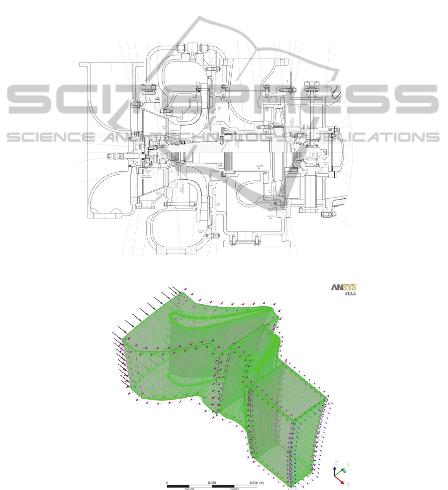
Turbocharger TK-32 (Figure 1) was developed at
LLC “Penzadieselmash” (Penza, Russian
Federation) for use on diesel generator 1А-9DG
manufactured by LLC “Kolomensky Zavod”.
During turbocharger’s operation there was a
necessity of engine forcing. As a result the
turbocharger operating condition was modified. In
particular, the rotor speed of the turbocharger
increased from 25500 to 28000 revolutions per
minute (rpm). In this regard LLC "Penzadieselmash"
applied for SSAU to assess the forcing effect on the
stress strain state of the turbine TK-32 and its gas-
dynamic efficiency, and make recommendations for
their improvement (Tikhonov, Matveev, 1982).
2 GAS DYNAMIC
CALCULATION OF TURBINE
BASIC DESIGN
Three-dimensional computational model of the flow
in the turbine stage, which includes zone of flow
around the nozzle guide vane (NGV), zone of flow
around the rotor wheel (RW) and free flow area at
the outlet of the turbine, was developed in Ansys
CFX program (ANSYS - Simulation Driven Product
Development, 2014). This model was used for
investigation of gas dynamic performances of the
existing turbocharger’s axial turbine. The flow
models of NGV and RW contain only one blade
passage for reducing required computer resources
and calculation time (Bonh, Heuer, Kusterer, 2005).
Therefore, the periodic boundary conditions were
implemented on lateral boundaries of the
computational domain (Figure 2).
Finite element mesh was created such as to
provide a value of y + no more than three. The total
number of elements was 250000 in the NGV mesh,
and 500000 elements in RW mesh. Tip clearance
was simulated when the RW mesh were created. The
value of tip clearance was taken as 1 mm in
accordance with the engineering drawing.
The following boundary conditions were set
during calculation:
mass flow rate (G = 5,34 kg/s), total
temperature (T* = 773 K) and flow direction
(perpendicular to the face) were set at the
computational domain’s inlet (NGV inlet);
595
Matveev V., Baturin O., Popov G. and Kolmakova D..
The Results of Gas Dynamic and Strength Improvement of Turbocharger TK-32 Axial Turbine.
DOI: 10.5220/0005042105950600
In Proceedings of the 4th International Conference on Simulation and Modeling Methodologies, Technologies and Applications (SIMULTECH-2014),
pages 595-600
ISBN: 978-989-758-038-3
Copyright
c
2014 SCITEPRESS (Science and Technology Publications, Lda.)
outflow boundary was set constant adjustment
of the flow static pressure (p = 105000 Pa)
constant at all channel height was set at the
computational domain’s inlet (RW outlet);
to account for the RW rotation, this area was
calculated in the rotating reference frame with
rotor speed n = 25500 rpm (nominal
conditions), n = 28000 rpm (forced mode);
The model of turbulence was SST k-
. The
calculation was performed in a stationary
formulation (Bochkarev, Dmitriev, Kulagin,
Makeenko, Mosoulin, Mossoulin, 1993). Flow
parameters at RW inlet and outlet were averaged in
the circumferential direction (Mixing Plane
approach).
The flow pattern, as well as flow parameters in
all points of considered flow region at nominal mode
(n=25500 rpm) and forced conditions (n=28000
rpm) were obtained. Analysis of the flow structure in
the turbine blade passage found no areas with
unfavorable flow pattern. Some flow parameters
distribution fields at turbine nominal mode
(n=25500 rpm) are given at Figure 3 and 4.
Predicted value of turbine efficiency at this mode
was
т
=83,6%.
Figure 1: Turbocharger TK-32.
Figure 2: Computational model of the flow in turbocharger TK-32 turbine.
SIMULTECH2014-4thInternationalConferenceonSimulationandModelingMethodologies,Technologiesand
Applications
596
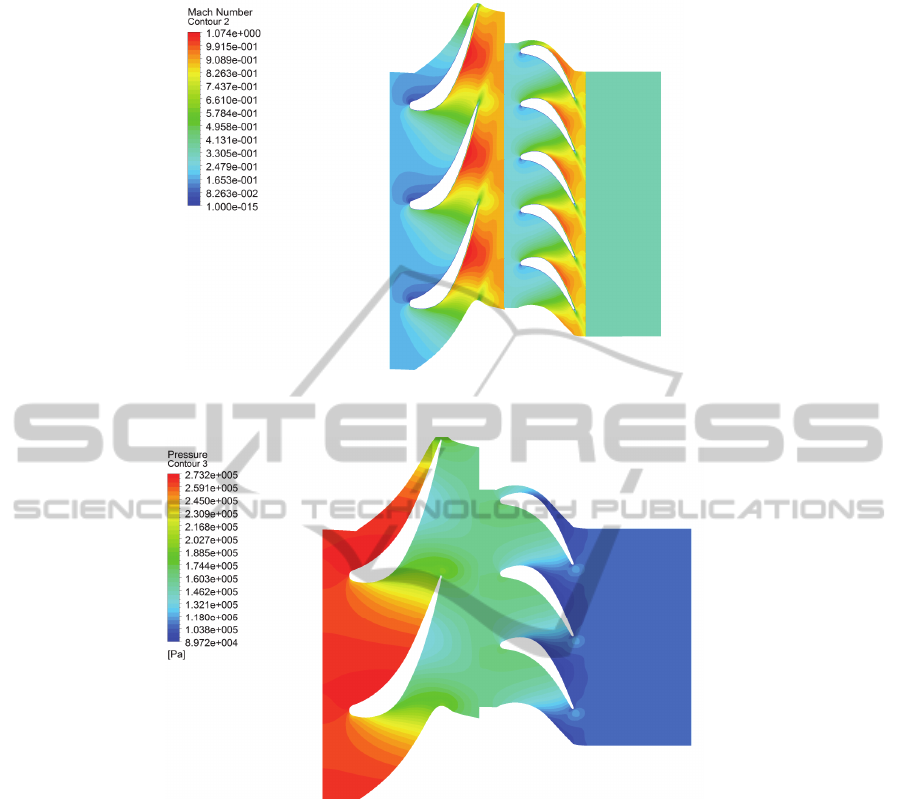
Figure 3: The field of Mach number’s value distribution in absolute reference frame at turbine middle diameter.
Figure 4: The field of static pressure distribution at turbine middle diameter.
3 THE STRENGTH ANALYSIS
OF TURBINE
The pressure and temperature fields at blades
surfaces obtained from gas dynamic calculation
were used as boundary conditions in turbine rotor
wheel’s static strength calculation by means of
Ansys Mechanical program. The modal for strength
calculation contained a whole rotor wheel,
consisting of a disc, blade attachment and blade
aerofoil. Since the computational model had cyclic
symmetry, then only the sector containing one blade
was modelled during the research. The periodic
boundary condition was implemented on its lateral
surfaces (Figure 5).
The computational model was loaded with gas
(obtained earlier in the Ansys CFX program) and
centrifugal forces. Disk temperature was adopted by
the thermometry data provided by LLC
"Penzadieselmash". Since the turbine disk is welded
to the shaft, the RW calculation model was fixed by
the front and rear flanges.
The computational model was divided by mesh
of Solid 185 and Solid 186 finite elements. Special
contact elements, limiting the movement of parts,
were used in areas of fir-tree root teeth contact with
disk slot.
Stress-strain state was evaluated at two modes:
nominal mode (n = 25500 rpm) and forced
conditions (n = 28000 rpm).
TheResultsofGasDynamicandStrengthImprovementofTurbochargerTK-32AxialTurbine
597
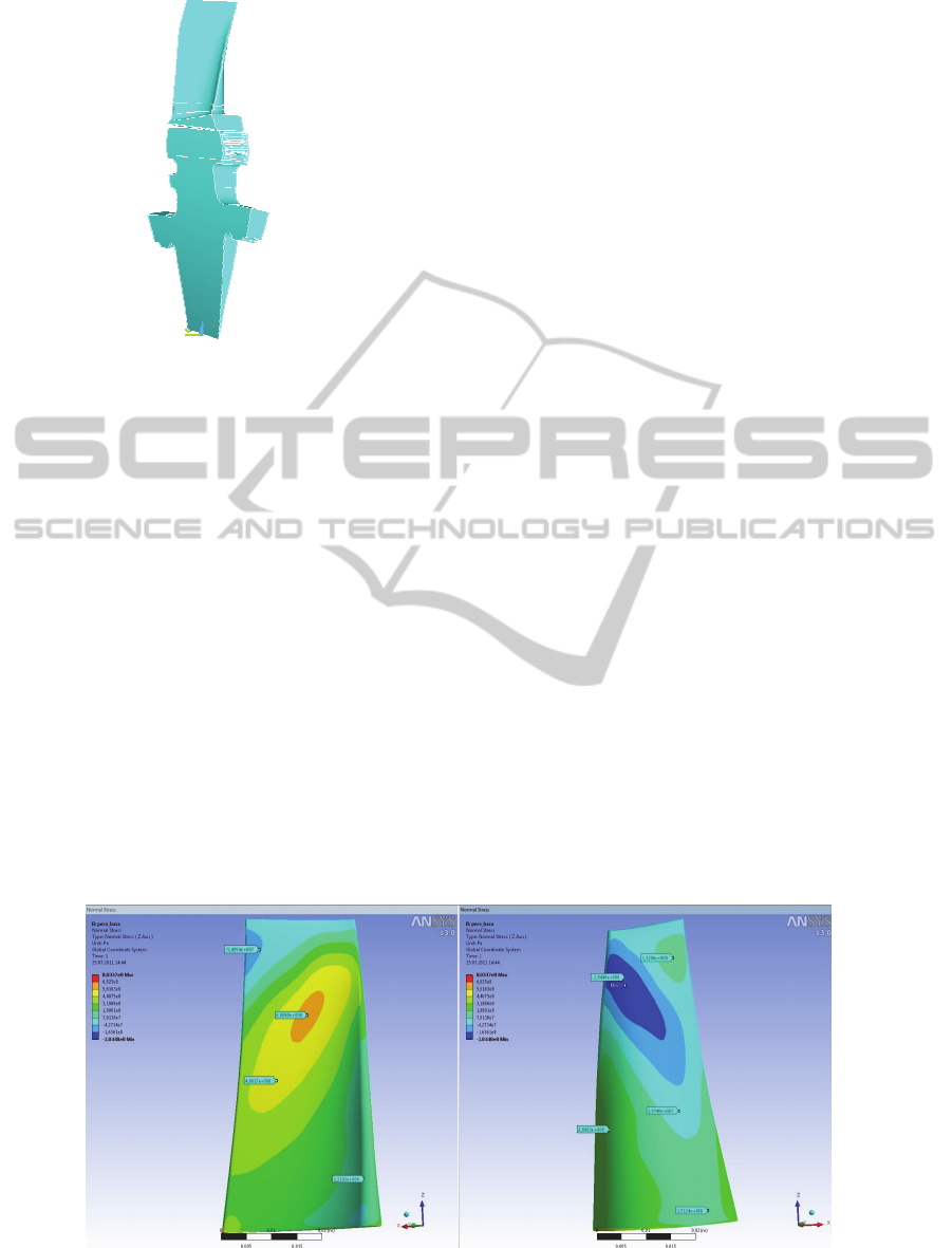
Figure 5: Computational model for turbocharger TK-32
turbine rotor wheel’s strength analysis.
The results obtained in the computation indicated
that turbocharger’s basic turbine satisfies the
strength conditions at the nominal mode (n = 25500
rpm) as a whole. However it should be noted that the
derived load factors are dangerously close to the
minimum value. Equivalent stress maximum value
was 600 MPa at forced mode (n=28000 rpm), which
corresponds to a load factor of 1.25. This value is
below the allowable value (permissible value of 1.3).
It was also revealed that there is plastic deformation
in footing parts of disc and blade.
Noteworthy is the fact that the maximum value
of stresses can be evidenced in the upper part of the
blade body at the level of two thirds from the root
(Figure 6), which indicates that stresses are caused
by the blade bending. This conclusion is supported
by the fact that compression stresses acts on the
suction side area, located beyond the region of
maximum stress. This conclusion is indirectly
confirmed by the cases of the upper third turbine
blades shedding of the turbocharger available in use.
4 THE MODERNIZATION OF
TURBINE
Elevated bending stresses are the result of a specific
form of the rotor blade body. Its top sections are
greatly expanded relatively bottom ones, violating
the sections centring on height. As a result,
centrifugal forces acting on the periphery part, cause
the increased torque, that bends the blade body.
To reduce bending stresses peripheral sections of
the blade have to be “shifted”. Hereinafter the term
"shift" means the displacement of blade body
sections of the pen in the circumferential direction.
To reduce the bending stresses in turbocharger
TK-32 turbine rotor blade body peripheral sections
have to be shifted in the circumferential direction
toward the suction side.
The effect of shift of three peripheral sections in
circumferential direction on the rotor wheel blades’
stress strain state was investigated. The variant
allowing to reduce the maximum value of stress up
to 506.8 MPa (18%) (peripheral section shifted by
the value of 0.05h towards the suction side) (Figure
7) at forced mode, which corresponds to the factor
load 1.49 (Figure 8), was found. It should be noted
that derived value of the load factor at the forced
mode (n = 28000 rpm) does not exceed the value of
the basic turbine version load factor at nominal
conditions (n = 25500 rpm). The flow in the
modernized turbine was investigated using Ansys
CFX.
Figure 6: Normal stress distribution on the basic blade body at n=28000 rpm (pressure side – on the left; suction side – on
the right).
SIMULTECH2014-4thInternationalConferenceonSimulationandModelingMethodologies,Technologiesand
Applications
598
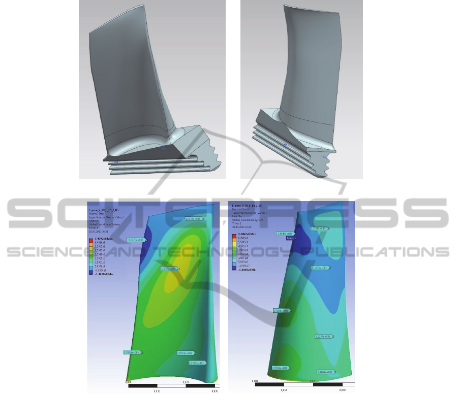
Figure 7: The appearance of modernized blade version.
Figure 8: Normal stress distribution on the modernized blade body at n=28000 rpm (pressure side – on the left; suction side
– on the right).
It was found that recommended variant of the
peripheral sections slope at the mode with n = 25500
rpm increases the turbine efficiency by 0.4%
(absolute).Modernization of Blade Attachment and
Blade Number Selection.
Alternative larger typical size of fir-tree root for the
elimination of plastic deformation in blade
attachment’s was selected. This in turn required
reduction the number of blades from 49 to 43 by
allocation on disk conditions.
The effect of rotor blades number on the
efficiency value was carried out in Ansys CFX in
order to evaluate the impact of this decision on the
turbine efficiency. The resulting dependence is
shown in Figure 9. The number of nozzle guide
vanes was not changed.
From the Figure it can be seen that the reduction
of RW blade number increases the turbine efficiency
by more than 1% for all versions of blade body. It is
related to the reduction of skin friction, number of
edged wakes decreasing and relative size of the
secondary vortices reduction. The value of
efficiency begins to drop again if the number of
blades more than 40 due to the reduction of torque
on RW blades.
Noteworthy the fact that blade version with
peripheral sections shift exceeds the base variant in
the gas-dynamic efficiency.
Analysing the diagram in Figure 9 it can be
concluded that the decrease of RW blades number
from initial 49 to 43...41 does not worsens the gas
dynamic turbine efficiency, but also improves it to
0.8...1.0%.
TheResultsofGasDynamicandStrengthImprovementofTurbochargerTK-32AxialTurbine
599
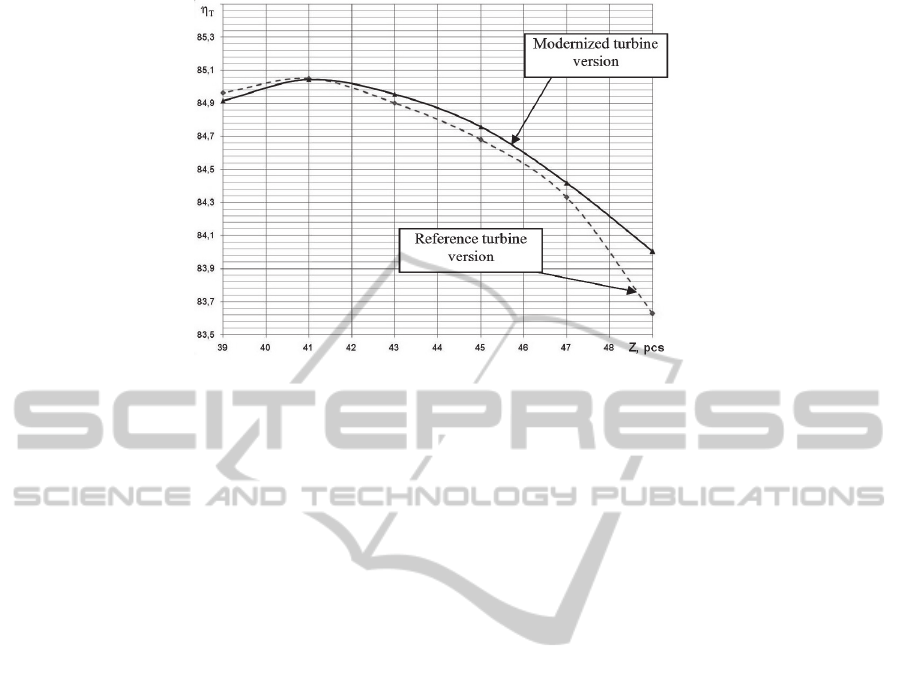
Figure 9: The turbine efficiency from number of RW blades dependence with constant number of NGV blades (dashed line
– basic blade version; solid line – blade with sections removal).
5 CONCLUSIONS
As the result of calculation research it was found
that turbine rotor blade of turbocharger TK-32,
manufactured by LLC "Penzadieselmash", will not
meet the strength conditions in case of engine
forcing up to n = 28000 rpm. The trouble spots of
the design are the blade bode and blade attachment.
In the course of the research it was found that
stress in the blade can be significantly reduced
through shifting of the three upper sections on 0,05h
in the circumferential direction towards the suction
side, replacing the blade attachment to another from
industry-specific standard (OST 1.10975-81) with an
opening angle
= 30 °, tooth pitch S = 3.2 mm, as
well as reducing the number of RW blades to 43
units, while maintaining the number of NGV.
The recommended variant of the basic blade
body modernization allows to satisfy the strength
conditions at all modes and to increase turbine
efficiency by 1%.
Turbocharger with number of rotor blades 43
was made and tested. The blade attachment and
blade body form was basic. The experiment showed
an increase in turbine efficiency by 1%, which fully
confirms the conclusions drawn by the authors.
ACKNOWLEDGEMENTS
The authors gratefully acknowledge the
comprehensive support of LLC “Penzadivelmash”
development design office staff, as well as staff of
SSAU department of Structure and Designing of
Engine for Flying Vehicles.
This work was financially supported by the
Ministry of education and science based on the
Government of the Russian Federation Decree of
09.04.2010 № 218 (code theme 2013-218-04-4777)
and in the framework of the implementation of the
Program of increasing the competitiveness of SSAU
among the world’s leading scientific and educational
centers for 2013-2020 years.
REFERENCES
Tikhonov, N.T., Matveev, V.N. 1982. Rational application
of microturbines with working fluid readmission. In
Soviet Aeronautics (English translation of Izvestiya
VUZ, Aviatsionnaya Tekhnika), vol. 25(3), pp. 93-98.
ANSYS - Simulation Driven Product Development
[Online], Available: http://www.ansys.com/ [10 Aug
2011].
Bohn, D., Heuer, T., Kusterer, K. 2005. Conjugate flow
and heat transfer investigation of a turbo charger. In
Journal of Engineering for Gas Turbines and Power,
vol. 127(3), pp. 663-669
Bochkarev, S.K., Dmitriev, A.Ya., Kulagin, V.V.,
Makeenko, S.V., Mosoulin, V.V., Mossoulin, A.A.
1993. Experience and problems of computer aided
thermogasdynamic analysis of testing results for gas-
turbine engines with complex schemes. In Izvestiya
Vysshikh Uchebnykh Zavedenij. Aviatsionnaya
Tekhnika, vol. 2, pp. 68-70.
SIMULTECH2014-4thInternationalConferenceonSimulationandModelingMethodologies,Technologiesand
Applications
600
