
Discrete Event System Based Pyroprocessing
Modeling and Simulation
Hyo Jik Lee, Won Il Ko, Sung Ki Kim, Seong Yeol Choi, Han Soo Lee,
Geun Il Park and In Tae Kim
Department of Nuclear Fuel Cycle System Development, Korea Atomic Energy Research Institute,
989-111 beon-gil Daedoekdaero, Yuseong, Daejeon, 305-353, Republic of Korea
Keywords: Discrete Event System, Pyroprocessing, Material Flow, Material Balance, Operation Model.
Abstract: The pyroprocessing operation-modelling is characterized as complicated batch type operation and tangled
material flow logic, and handling many numbers of chemical elements. Discrete event system modeling was
performed to build an integrated operation model, a simulation of which showed that a dynamic material
flow was implemented. All data related to a dynamic material flow were recorded in database tables, and
used for verification and validation in terms of material balance. Compared to equilibrium material balance,
dynamic mass balance showed that the amount of material transported upstream and downstream in the unit
process satisfied the mass balance equation at every batch operation. This study also showed that a dynamic
material flow, which is a basic framework for an integrated pyroprocessing simulator, was well working.
The integrated model built thus far will be improved in a few years toward an integrated simulator with
safeguards assessment, technical feasibility, and economic feasibility modules.
1 INTRODUCTION
The Korea Atomic Energy Research Institute
(KAERI) has been developing pyroprocessing
technologies, which can reduce the increasing
amount of spent nuclear fuel (SNF) and dramatically
decrease the disposal load, through recycling and
destroying toxic waste such as long-life fission
products in the SNF. Pyroprocessing technology has
not been fully demonstrated in terms of
commercialization and technology maturity. To
navigate the right direction of pyroprocessing
technology development, a demonstration in an
integrated facility is certainly a tangible solution, but
it is too costly and time consuming to construct a
fully integrated facility including all unit processing
and remote handling equipment. Actually, modelling
and simulation enhance an understanding of known
systems, provide qualitative and quantitative insight
and guidance for experimental work, and produce
quantitative results that replace difficult, dangerous,
or expensive experiments (DePaoli, 2011).
Therefore, a technology assessment and
breakthrough by modelling and simulation would be
preferable even in pyroprocessing technology
development. In this study, the main concern is to
build a consolidate framework able to describe the
material flow of an integrated pyroprocessing
facility and to build a model on that. This study is
on-going mid-term research to aim at a multi-
purpose integrated pyroprocessing simulator. As a
basic frame of the simulator, the material flow
modelling and mass balance management were
carefully designed and applied to the simulator.
Mass balancing model was studied about iron ore
terminal example by using mixed discrete and
continuous model (Béchard, 2013). In this study, a
discrete event based system (DES) appropriate to
build a model of a batch type process is applied to
the configuration of the pyroprocessing material
flow. Dynamic in-out material balance in the unit
process is managed in the database whenever events
according to the material flow occur. The progress
on the simulator was verified in terms of rigorous
implementation of operation logic and mass balance.
2 PYROPROCESSING
An integrated pyroprocess is under consideration to
590
Jik Lee H., Il Ko W., Ki Kim S., Yeol Choi S., Soo Lee H., Il Park G. and Tae Kim I..
Discrete Event System Based Pyroprocessing Modeling and Simulation.
DOI: 10.5220/0005010005900596
In Proceedings of the 11th International Conference on Informatics in Control, Automation and Robotics (ICINCO-2014), pages 590-596
ISBN: 978-989-758-039-0
Copyright
c
2014 SCITEPRESS (Science and Technology Publications, Lda.)
process the spent oxide fuel discharged from PWRs
and fabricate metallic fuel containing transuranic
(TRU) elements for a future sodium cooled fast
reactor (SFR) (Yoo et al., 2008). The process
includes head-end process, electrolytic reduction,
electro-refining, electro-winning, and a salt waste
treatment system.
The pyroprocessing also includes many complex
recycling flows. Since it almost consists of batch-
type processes even though some are more like
continuous processes, a discrete event system is
preferred to model it. A lot of effort has been put
into an investigation of principle (Song et al., 2010;
Lee et al., 2011). Since current experimental studies
focus on the unit process technology, and not an
integrated process, it is hard to predict the overall
behaviour and mutual influence. However, modeling
and simulation can make it possible to see
unforeseeable behaviour.
3 MODELING AND SIMULATION
3.1 Operation Model
3.1.1 Discrete Event and Hybrid System
The operation model in the pyroprocessing simulator
is located between the process model and facility
model (Lee et al., 2013). Although the process
model is involved in a pyrochemical reaction within
a batch, the operation model is engaged in states in
border of batch, that is, states driven by the start and
end of the batch operation. The state transition
driven by event in the operation model is what the
DES modeling describes the best. On the other hand,
a time-dependant state in the process model can be
well described in a continuous variable dynamic
system (CVDS). This is why the pyroprocessing
simulator is a hybrid system. In this paper, the
operation model is focused more than in the process
model because the process modelling and hybrid
system modelling was explained in a previous study
(Lee et al., 2013).
3.1.2 Operation Procedures
We do not have as much information on the
pyroprocessing operation as a real existing facility
operation. Therefore, gathering the operation
information is limited. However, baseline operation
procedures for a rational process operation can be
drawn by professionals involved in the process
development. Since pyroprocessing often has
recycling and complex operations, to build an
operation model to meet such requirements is not
that simple.
For example, the oxide reduction process (Karell
and Gourishankar, 2001; Herrmann et al., 2005; Hur
et al., 2008) includes three unit processes such as
electrolytic reduction (P2-1), cathode processing
(P2-2), and LiCl purification (W4-1) as shown in
Figure 1. P2-1 converts two types (pellet and
fragment) of oxide fuels into metal ones by
electrolytic reduction, P2-2 evaporates and recovers
entrained salt in a cathode product carried from P2-1,
and then recycles the recovered salts during the first
campaign (1st through 40th batch) but sends them to
W4-1 after the first campaign (41st batch ~ ). The
recovered salt is added in P2-1 every other batch
(3rd, 5th, 7th, … 39th batch) operation during the
first campaign. The recovered salt is regenerated in
W4-1 to be recycled to P2-1 from the third campaign
(81st batch ~). During the second campaign (41st
batch through 80th batch), P2-1 needs new salt to
compliment insufficient salt corresponding to
entrained salt accompanied by a cathode product,
and P2-2 holds the recovered salt until it reaches an
amount sufficient to feed W4-1. From the third
campaign, P2-1 receives the regenerated salt during
every other batch operation, and new fresh salt can
then be added if it is insufficient.
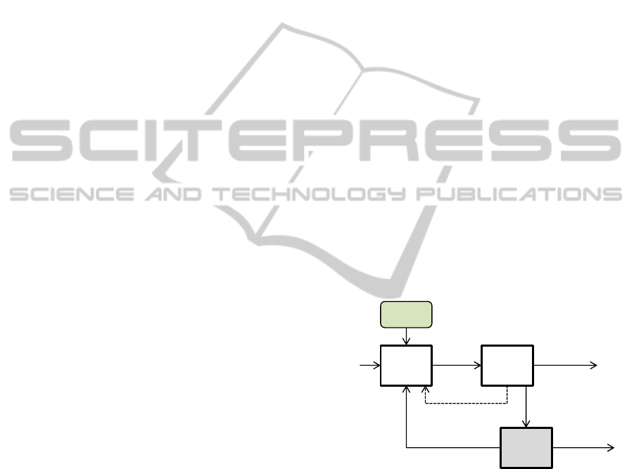
Figure 1: Material flow diagram for oxide reduction.
The above operation requirement is changed
according to the batch operation number.
Consequently, the material flow direction changes.
To reflect such complex flow change in a model, a
well-designed logic based model should be built.
3.1.3 Operation Modeling
Operation logic in 3.1.1 was implemented in an
ExtendSim
TM
v8. Routing modeling is built based on
DES, as shown in Figure 2, as a feed material for
one batch is considered to be an item. The oxide
reduction model begins with the transport block that
P2‐1
Electrolytic
Reduction
P2‐2
Cathode
Processing
W4‐1
LiCl
Purification
Newsalt
(LiCl,Li
2
O)
Reduced
metal
withsalt
RecoveredSalt
(1
st
campaign)
RegeneratedSalt
(from3
rd
campaign)
Reducedmetal
Pellet,
fragment
ConcentratedSalt
DiscreteEventSystemBasedPyroprocessingModelingandSimulation
591
Figure 2: Logic model of feed material receipt in P2-1.
Figure 3: Blocks needed for operation logic.
represents three types of feed material (SNF,
recovered salts, and regenerated salts) receipt. SNF
is always needed for every batch operation.
However, the recovered salts and regenerated salts
can be received or not according to the batch
operation number. Such routing logic is
implemented by an equation block and batch blocks,
as shown in Figure 3.
Equation block includes complex logic
behaviour describing the operation condition, for
example, whether the current batch operation
requires the addition of new, recovered, or
regenerated salt. If an addition is needed, a
corresponding batch quantity in the batch block is
set to TRUE. The pseudo-code for the equation
block is as follows:
// Batch #: 1
if(BatchNum == TRUE)
addNewSalt = TRUE;
addRecycledSalt = FALSE;
addRegenSalt = FALSE;
// Batch #: 3, 5, 7, ... ,39
else if((BatchNum <= 40) &&
(Realmod(BatchNum-1, 2) == 0))
{
addNewSalt = FALSE;
addRecycledSalt = TRUE;
addRegenSalt = FALSE;
}
// Batch #: 2, 4, 6, ... ,40
else if((BatchNum <= 40) &&
(Realmod(BatchNum, 2) == 0))
{
addNewSalt = FALSE;
addRecycledSalt = FALSE;
addRegenSalt = FALSE;
}
// Batch #: 41, 43, 45, ..., 79
else if(BatchNum >= 41 && BatchNum <=
80 && Realmod(BatchNum, 2) == 1)
{
addNewSalt = TRUE;
addRecycledSalt = FALSE;
addRegenSalt = FALSE;
}
// Batch #: 42, 44, 46, ..., 80
else if(BatchNum >= 41 && BatchNum <=
80 && Realmod(BatchNum, 2) == 0)
{
addNewSalt = FALSE;
addRecycledSalt = FALSE;
addRegenSalt = FASLE;
ORF eedInORF eedIn
RecSaltInRecSaltIn
0
D U
BatchNum
y=f(x)
1
1
D U
y=f(x)
{...}
0
0
1
2
demand
AD
addRegenLiCl
RegenSaltInRegenSaltIn
1
1
D U
0
0
1
2
addRegenLiCl
addRegenLiCl
i
rL
#
addNewLi2O
addNewLiCl
addRecycledLiCl
addRecycledLiCl
VesselRegLiCl
FeedFormOR
0
TR U
BB RegLiCl
Stats
Calculate
P1-3-ORf eed
Stats
Calculate
P2-2-toORRecLiCl
i
r L
#
Stats
Calculate
W4-1-RegenSalt
i
r L
#
G_O pen
demand
AD
i
r L
#
BatchNum
ORFeedInORFeedIn
0
D U
RecSaltInRecSaltIn
0
D U
RegenSaltInRegenSaltIn
0
D U
InCNT
y=f(x)
addRegenLiCl
addNewLi2O
addNewLiCl
addRecycledLiCl
0
0
1
2
addRecycledLiCl
0
0
1
2
addRegenLiCl
Transport block
Equation block
Batch Blocks
ICINCO2014-11thInternationalConferenceonInformaticsinControl,AutomationandRobotics
592
Figure 4: Mass composition calculation of feed (input) and product materials (output) in P2-1.
}
// Batch #: 81, 83, ....
else if(BatchNum >= 81 &&
Realmod(BatchNum, 2) == 1)
{
if(ReqSalt > RegSalt)
addNewSalt = TRUE;
else
addNewSalt = FALST;
addRegenSalt = TRUE;
addRecycledSalt = TRUE;
}
The first inputs of two batch blocks are for the
receipt of pellet/fragment, which starts from the
ORFeedIn connector. The batch blocks merge the
first and second input items into one new item. The
second input item number is controlled by the
equation block to be set to 0 (FALSE) or 1 (TRUE).
In the case of FALSE, the batch block converts only
the first item into one new item.
A receipt of regenerated and recycled salt means
the P2-1 process has a recycling material flow from
another unit process. In this way, complex recycling
is easily incorporated into a routing model through
equation and batch blocks.
3.1.4 Material Flow Management
Material dealt with in the pyroprocessing simulator
consists of 52 elements for SNF and 23 elements for
chemical additives needed for pyroprocessing. A
total of 75 elements are calculated and written in a
record of the database table whenever each event
occurs. To access ExtendSim’s internal database
table, equation blocks for the mass balance
calculation are inserted at an appropriate position in
the model. The first equation block in Figure 4,
which is an item equation block different from the
equation block in Figure 3, calculates the salt
composition in a bath when an item passes through
the equation block after receiving and merging a
pellet/fragment with recovered or regenerated salt,
and the item then passes through pre-process,
process, and post-process sequentially. Because an
electrolytic reduction generates two types of
products such as O
2
and cathode product, the
material should be separated into two products. An
unbatch block plays a role of an item separation and
each equation block actually calculates each product
composition, as shown in Figure 4.
Figure 5: Blocks for mass calculations and process
operation delay.
Figure 5 shows equation blocks to calculate an in-
bath salt composition after receiving the feed
material, and product composition after process
operation. The codes in the equation blocks for mass
composition calculation directly access the database
tables to write, read, delete, and create data. The
equation blocks in Figures 4 and 5 are item blocks
and are able to be located anywhere in the item flow.
Therefore, a mass composition can be timely
calculated according to the material flow and event
driven modelling for a material flow to be possible.
0
D F
preprocess
0
D F
process
0
D F
postprocess
y=f(x)
NewCampaign?
O2
CathodeDeposit
i
r L
#
i
r L
#
Pretime
Posttime
addRegenLiCl
addNewLi2O
addRecycledLiCl
addNewLiCl
y=f(x)
Cathode Deposit
y=f(x)
O2
i
r L
#
y=f(x)
AddedLiCl
AddedLi2O
ReqLiCl
ReqLi2O
Pretime
Posttime
Proctime
Proctime
y=f(x)
O2
y=f(x)
Cathode Deposit
addRegenLiCl
addNewLi2O
addRecy cledLiCl
addNewLiCl
y=f(x)
AddedLiCl
AddedLi2O
ReqLiCl
ReqLi2O
Product
Reaction
Salt addition
D F
preproces s
D F
process
D F
postprocess
Pretime
PosttimeProctime
DiscreteEventSystemBasedPyroprocessingModelingandSimulation
593

Process operation (electro-chemical reaction) is
simply modelled with three activity blocks so that
each activity (pre-processing, processing and post-
processing) consume each specific time. In this part,
the processing activity block can be replaced with a
process model if it exists.
3.2 Material Balance
3.2.1 Equilibrium Material Balance
The integrated pyroprocessing simulator is designed
on a basis of dynamic material balance. On the other
hand, a flowsheet study (Lee et al., 2012) is based on
equilibrium mass balance at a specific time, for
example, at the end of year. Since equilibrium
material balance simply indicates the accumulation
of material transported through steam at a specific
time, the calculation of equilibrium mass balance
after a long period has an average effect such that
transient changes are diminished over time. An
equilibrium material balance represents the overall
static characteristic, but a dynamic one shows the
exact material balance change at any specific
instance in time. An equilibrium mass balance in
process P2-1 is shown in Table 1. This result is
obtained from the accumulated transported mass via
input and output streams after 200 batch operations,
which correspond to 10 tons/year of annual
throughput, have finished.
Table 1: Equilibrium material balance in P2-1.
Material via Stream type SNF mass (kg)
new salt feed -
pellet/fragment feed 11,331
recovered salt feed 5
regenerated salt feed 6
Input Sum 11,341
cathode product product 9,997
O
2
product 1,331
Output Sum 11,328
remaining salt hold-up 13
Since equilibrium mass balance shows accumulated
results over numerous batches, a difference of each
batch is ignored. Process P2-1 has a total of four
inputs and two outputs. Sums of inputs and outputs
are not the same. However, considering that process
P2-1 can hold a small amount of SNF in its bath, the
mass balance is satisfied. We cannot predict from
the equilibrium mass balance any result affected by
the operation procedure described in section 3.1.1.
3.2.2 Dynamic Material Balance
Table 2 represents the mass of inputs and outputs
calculated whenever every process batch operation
is completed. Process P2-1 receives 50 kgHM/batch
from a previous process. The second column in
Table 2 represents the mass of pellet/fragment oxide.
Excluding the oxide weight, it becomes 50
kgHM/batch. The operation procedure in sections
3.1.1 and 3.1.2 indicates that the recovered salt is
added at every other batch during the first campaign,
and the third batch operation expects a receipt of the
recovered salt from P2-2. However, in the third
batch operation, P2-1 does not receive the recovered
salt because P2-2 has not prepared another recovered
salt by then. Such a dedicate behaviour cannot be
estimated in the equilibrium mass balance.
Table 2: Dynamic material balance in P2-1.
batch # fragment/
pellet (kg)
recovered
salt (kg)
regenerated
salt (kg)
remaining
salt (kg)
cathode
product (kg)
O2
(kg)
1 56.67 - - 0.28 49.72 6.67
2 56.67 - - 0.54 49.73 6.67
3 56.59 0.02 - 0.83 49.74 6.59
4 56.67 - - 1.08 49.75 6.67
5 56.59 - - 1.33 49.75 6.59
6 56.67 - - 1.57 49.76 6.67
7 56.59 0.05 - 1.85 49.77 6.59
8 56.67 - - 2.08 49.77 6.67
9 56.59 0.08 - 2.38 49.78 6.59
…
41 56.59 - - 10.25 49.97 6.59
42 56.67 - - 10.27 49.98 6.67
43 56.59 - - 10.30 49.97 6.59
44 56.67 - - 10.32 49.98 6.67
45 56.59 - - 10.35 49.97 6.59
46 56.67 - - 10.37 49.98 6.67
47 56.59 - - 10.40 49.97 6.59
…
81 56.59 - 0.08 11.03 49.99 6.59
82 56.67 - - 11.04 50.00 6.67
83 56.59 - 0.08 11.13 49.99 6.59
84 56.67 - - 11.13 50.00 6.67
85 56.59 - 0.08 11.21 49.99 6.59
86 56.67 - - 11.22 50.00 6.67
87 56.67 - 0.08 11.30 49.99 6.67
…
194 56.67 - - 13.30 50.05 6.67
195 56.67 - 0.11 13.37 50.04 6.67
196 56.67 - - 13.32 50.05 6.67
197 56.67 - 0.12 13.39 50.04 6.67
198 56.67 - - 13.34 50.05 6.67
199 56.67 - 0.12 13.41 50.04 6.67
200 56.67 - - 13.36 50.05 6.67
sum 11,331 5 6 13.36 9,997 1,331
ICINCO2014-11thInternationalConferenceonInformaticsinControl,AutomationandRobotics
594

It shows that regenerated salt is provided at every
other batch operation from the third campaign (81th
batch ~) in the 4th column in Table 2, as expected in
section 3.1.1. Since the remaining salt always exists
in the bath of P2-1, the 5th column in Table 2
indicates the current accumulated state in the bath.
The amount of products increases as the campaign
increases because a small amount of SNF elements
accompanied by regenerated salts is added in P2-1
from the 3rd campaign. A summation of the input
and output materials over 200 batch operations in
Table 2 means accumulated transported mass
through input and output streams. The accumulation
of each batch operation results is exactly the same as
the equilibrium mass balance in Table 1. Compared
to the equilibrium mass balance, the dynamic mass
balance gives a lot of information on the state at a
specific instance in time, i.e., how much material has
been processed, how many products have been
produced, how much of the material has been held
up, and how much material remains in temporary
storage while waiting for the next process.
4 VERIFICATION
AND VALIDATION
4.1 Models & Codes
Logics and models for operation modeling are
verified from a material flow point of view. Many
debugging tools and utility blocks support the
building of an integrity model. Debugging the item
flow and equation are necessary to detect problems
and fix them to accomplish the completeness of a
model. In the model level, a pausesim block is
located anywhere and stops the simulation progress
at a user intended point. In the code level, a set break
point will stop the programming code in the
equation block running at a user intended point. The
integrated pyroprocessing model includes a very
complicated item flow, and thus a debugging
process is needed to guarantee item flow logic. It
also includes many equation blocks to build a
complicated operation procedure and calculate the
mass composition. Therefore, to debug such
equations is also necessary. Whenever a unit process
model is developed, not only is the model itself
debugged, the integrated operation model is also
verified.
Validation is quite difficult to perform at this
moment because there is no existing integrated
facility using SNF. However, lab-scale based
experimental results using simulated fuels, which are
not real SNF but are able to simulate real SNF to a
certain degree, can be validation data. Such results
have already been used in the model to obtain
material composition of the product. Therefore, the
material composition of every product should be
checked at every batch operation to satisfy the
separation factor as obtained in the experiment.
4.2 Material Balance
Once the unit process is modelled, the mass balance
equation must be satisfied for every batch operation
through an investigation into the related database
tables.
,
,
(2)
where is the number of inputs, is the number of
outputs, is the current number of batch operations,
,
is the k-th input amount of mass transported
through the i-th upstream,
,
is the k-th output
amount of mass transported through the i-th
downstream, and
is the hold-up until the k-th
batch.
The bracket in equation (2), which represents the
difference between the current and previous hold-up,
means the contribution by only the current batch
operation because a hold-up inherently involves
accumulation. For example, for the 9th batch
operation in Table 2, the mass balance equation (2)
is satisfied as follows:
Table 3: Mass balance equation in the 9th batch operation.
9-th
inputs
9-th outputs 8-th hold-
up
9-th hold-up
56.59
0.08
0.00
49.78
6.59
2.08
2.38
56.67 = 56.37 + 0.30
After the current batch (9th batch), an operation
hold-up represents 2.38 kg, but the contribution by
the current batch operation is exactly 0.30 kg. Any
other batch operation satisfies the mass balance
equation as the result of the 9th batch operation. The
above results must also be satisfied even though a
gross mass decomposes into the type and element
level. The proof is skipped in this paper due to
limitations.
DiscreteEventSystemBasedPyroprocessingModelingandSimulation
595

5 CONCLUSIONS
The integrated pyroprocessing features are a batch
type operation, complicated recycling, and tangled
operation logic. An item flow model based on DES
enables a flow control, mass balance calculation, and
basic framework of an integrated pyroprocessing
simulator. Compared to a static or equilibrium
material flow, a model-based dynamic material flow
provides detailed information and thus a careful
analysis of every batch is necessary to confirm the
mass balance results. Verification and validation
regarding the model built thus far has been
performed in terms of the mass balance calculation,
and shows the completeness of the model. However,
the modeling has not been finished but is still under
progress.
To improve the operation model toward a multi-
purpose integrated pyroprocessing simulator, various
modules must be incorporated at a facility level. One
of the issues on a new recycling process such as
pyroprocessing is to guarantee integrated safeguards
in terms of material accountancy and security. Mass
tracking is the most fundamental requirement for a
model to cope with for safeguards assessment. Since
the material flow framework in the current model
can support a perfect mass tracking on an element
basis, a safeguards module is expected to be
developed without difficulty and to be added in an
integrated simulator. Technical feasibility can also
be supported by an integrated simulator to determine
or recommend process operation conditions by
adding an optimization module. Compared to other
reprocessing technologies, economic feasibility must
be tested in a simulation by developing a cost
evaluation module. It is expected that an integrated
pyroprocessing simulator fulfilling the above
described functions by add-on modules will be
released in a few years.
ACKNOWLEDGEMENTS
This work was supported by Nuclear Research and
Development Program of National Research
Foundation of Korea (NRF) funded by Ministry of
Science, ICT and Future Planning (MSIP).
REFERENCES
DePaoli, D., 2011. Modeling and simulation of nuclear
fuel recycling systems, short course of “Introduction to
nuclear chemistry and fuel cycle separations.”
Bechard, V., 2013. Simulation of mixed discrete and
continuous systems: an iron ore terminal example, In
Proceeding of the 2013 Winter Simulation Conference,
1167-1178.
ExtendSim Simulation Software. Imagine That Inc, 2014.
Web. 24 Jun 2014. <http://www.extendsim.com>
Lee, H. J. et al., 2012. Pyroprocessing baseline flowsheet
v4.0, talks in KAERI.
Lee, H. J. et al., 2013. Design for integrated
pyroprocessing plant level simulator, Annals of
Nuclear Energy, 60, 316-328.
Phongikarron, S., Herrmann, S., Simpson, M., 2011.
Diffusion model for electrolytic reduction of uranium
oxides in a molten LiCl-Li2O slat, Nuclear
Technology, 174, 85-93.
Yoo, J. H. et al., 2008. A conceptual study of
pyroprocessing for recovering actinides from spent
oxide fuels. Nucl. Eng. Technol. 40, 581–592.
Song, K. C., Lee, H., Hur, J. M., Kim, J. G., Ahn D. H.,
and Cho, Y. J., 2010. Status of pyroprocessing
technology development in Korea, Nuclear
Engineering Technology, 42(2), 131-144.
Lee, H., Park, G. I., Kang, K. H., Hur, J. M., Kim, J. G.,
Ahn, D. H., Cho, Y. J., and Kim, E. H.,
Pyroprocessing Technology Development at KAERI,
Nucl Eng Tech, 43(4), 317-328.
Karell, E. J., and Gourishankar, K. V., 2001. Separation of
Actinides from LWR Spent Fuel Using Molten Salt
Based Electrochemical Process, Nucl. Tech., 136, 342.
S. D. Herrmann, S. X. Li, and M. F. Simpson, 2005.
Electrolytic Reduction of Spent Oxide Fuel – Bench-
Scale Test Results, Proc. Global 2005, No. 488,
Tsukuba, Japan, October 9-October 13.
J. M. Hur, I. K. Choi, S. H. Cho, S. M. Jeong, C. S. Seo,
2008. Preparation and Melting of Uranium from U3O8
J of Alloys and Compounds, 452, 23.
ICINCO2014-11thInternationalConferenceonInformaticsinControl,AutomationandRobotics
596
