
Development of Training Simulator for Sway Suppression Skills on
Shipboard Rotary Cranes
Yusaku Matsuda, Shoma Fushimi and Kazuhiko Terashima
Toyohashi University of Technology, The Mechanical Engineering Department,
System and Control laboratory, Hibarigaoka 1-1, Tempaku town, Toyohashi city, Japan
Keywords:
Ship control, Training, Industrial control, Human-machine interface, Teaching, Virtual reality.
Abstract:
In this paper, we develop the operational training system by teaching control input to crane operators. In
particular, it is applied to the sway suppression control of load, by utilizing optimal control input. If crane op-
erators can replicate its control input, they can operate crane suppressing the load sway, and hope the advance
of training effect. Firstly, we build a shipboard rotary crane simulator, and verify the validity of the training
simulator by transfer simulation. Nextly, it presents a sway suppression control method to obtain control input
for crane operators, and proposes the training system to teach its control input to operators. Finally, the crane
simulator integrates this training system, and the proposed training system verifies the validity by subjects
experiments.
1 INTRODUCTION
A shipboard crane that is equipped on the ship is
widely used for cargo work in harbors or construc-
tion sites. Many kinds of shipboard crane are such as
small crane salvage barge that is several hundred tons;
bucket dredger that is used for digging or removing
mud and sand; and large non-sailing crane barge that
is thousands of tons. Recently, shipboard crane have
become larger for construction of pipeline, installa-
tion of caisson or offshore work in harbor or seacoast.
Generally, large shipboard crane had no rotary func-
tion. However, rotary shipboard crane that is effec-
tive for work has also become larger recently. Large
shipboard crane is required quick working, because
you must pay out very expensive anchorage charges.
So, it is required that the sway of the load is sup-
pressed and you transport it quickly. However, these
were depended heavily on the technique of skilled
operator. Additionally on the shipboard, ship sway
is also generated by wave and crane motion. Thus,
operators must consider these matters and operation
is very difficult. On the other hand, operation work
of a crane is considered to be typical one of heavy,
dirty and dangerous work. So, shortages of skilled
operator have become serious problem. As solution
of these problems, in this study, a training assist sys-
tem for novice operator is proposed. The training us-
ing real machine has the risk of serious accident. In
addition, acquisition of safety and quick transporta-
tion technique is required a certain level of experi-
ence. So, safety environment for operation training
required. As alternative method of training using
real crane, crane simulators have been actively devel-
oped(Jiung Yao Huang, 2003)(Mohammed F.Daqaq,
2003). If you use these simulators, you can safely
and easily train without accident by the operating mis-
take. Currently, various realistic crane simulators that
are reappeared real work environment have been de-
veloped(R.Ito, 2009)(K.Watanuki, 2007). However,
many simulator cannot contribute to reduction of the
training time, because try and error exercise are re-
quired. In this study, the training assist system that
applies a human sense is developed. The purpose of
our study is development of the simulator such that
novice operator can efficiently master complex oper-
ation technique of the shipboard rotary crane. And we
discuss construction of better control system.
2 THE SYSTEM CONSTRUCTION
This system is comprised of shipboard rotary crane
training simulator and operating interface. Proposed
shipboard crane simulator is used existing graphics li-
brary (OpenGL) of highly-portable. Active-joystick
is employed as operating interface. Trainees operate
shipboard crane on the simulator while seeing display
433
Matsuda Y., Fushimi S. and Terashima K..
Development of Training Simulator for Sway Suppression Skills on Shipboard Rotary Cranes.
DOI: 10.5220/0005008104330440
In Proceedings of the 11th International Conference on Informatics in Control, Automation and Robotics (ICINCO-2014), pages 433-440
ISBN: 978-989-758-039-0
Copyright
c
2014 SCITEPRESS (Science and Technology Publications, Lda.)
monitor and using active joystick.
2.1 Graphics Library
3D graphics library of the simulator is using OpenGL.
OpenGL have functions such as 3D display, control of
the colors or pattern, geometric transform and shading
compensation. So, OpenGL is a simple graphics free
software. In addition, OpenGL can develop a system
without dependence for operating system.
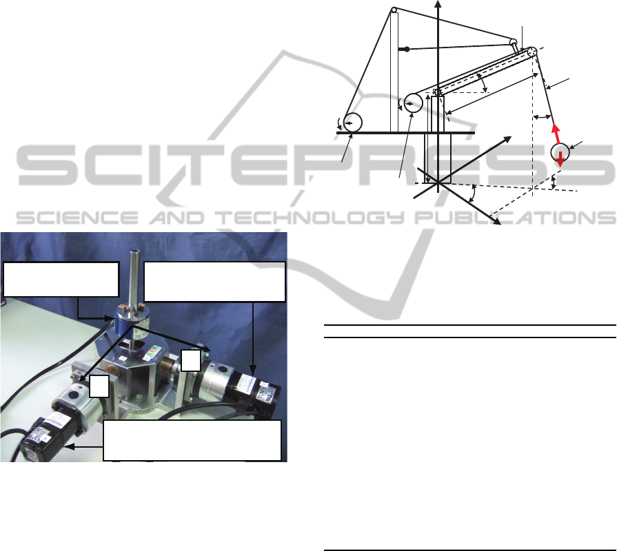
2.2 Interface for Operation - Active
Joystick
Operating interface employs active-joystick devel-
oped in our laboratory (Fig.1). This active-joystick
has 6-axis force sensor, and X and Y-axis AC servo
motor. Firstly, force sensor feels operator’s force.
Second, AC servo motor is driven depending on oper-
ator’s force. AC servo motor realizes smooth motion
of the active-joystick, because of the compliance con-
trol.
AC servomotor
(Boom-hoistingref erence)
AC servomotor
(Rotaryreference)
Force/Torque sensor
J
X
J
Y
AC sevomoter
(Rotary reference)
AC sevomoter
(Boom-hoisting reference)
Force / Torque
sensor
Y
J
X
J
Figure 1: Experimental equipment of active joystick.
3 SHIPBOARD ROTARY CRANE
MODEL
In this study, shipboard rotary crane model is con-
structed of both the rotary crane model and a brief
ship model.
3.1 Rotary Crane Model
Schematic diagram of the target rotary crane is shown
in Fig. 2 and its parameter is shown in Table 1. In or-
der to simplify the system, the following assumption
is summarized:
• A crane is a rigid body.
• The load is a mass point.
• The rope’s weight, deflection and elasticity are ig-
nored.
• The friction and backlash for the power transmis-
sion device are inored.
m
φ
B
L
1
r
m
l
2
r
Y
θ
α
~
β
~
X
H
l
Boom
Rope
Load
Dram Boom
Dram Rope
Z
mg
F
z)y,(x,
)z
~
,y
~
,x
~
(
φ
Figure 2: Schematic diagram of rotary crane for a load po-
sition model.
Table 1: Parameter of a load position model.
Symbol Unit Appellation
θ rad rotary angle
φ rad boom angle
l m length of the rope
L
B
m length of the boom
H m height of the turn table
m
L
kg mass of the suspended load
m
B
kg mass of the boom
m
S
kg mass of the ship
g m/s
2
gravity
F N tension of the rope
v
W
m/s wind velocity
˜
α rad swing angle on the horizontal surface
˜
β rad swing angle from the vertical direction
α rad swing angle on the X-axis direction
β rad swing angle on the Y-axis direction
( ˜x, ˜y, ˜z) m position of the crane tip
(x,y,z) m position of the load
(v
Wx
,v
Wy
,v
Wz
) m/s wind velocity of each axis direction
The motion of a rotary crane is different from the
linear motion of an overhead crane or a gantry crane.
In the case of a rotary crane, the motion of the load
has an arc-like trajectory, and considering the effect
of centrifugal force, it is necessary to model the load
sway as a circular cone pendulum. A diagrammatic
illustration of a rotary crane is shown in Fig 2. In
addition, the system is simplified by the following
assumption. By seeing Fig.2, the boom tip position
in the crane coordinate ( ˜x
′
, ˜y
′
, ˜z
′
) is calculated using
ICINCO2014-11thInternationalConferenceonInformaticsinControl,AutomationandRobotics
434

Eqs.(1)-(3) as follows:
˜x
′
= L
B
cosφcosθ (1)
˜y
′
= L
B
cosφsinθ (2)
˜z
′
= H + L
B
sinφ (3)
Coordination transformation from Σ
′
to Σ is done us-
ing Eq.(4).
˜
X = T
xyz
˜
X
′
(4)
d
˜
X
dt
=
dT
xyz
dt
˜
X + T
xyz
d
˜
X
′
dt
(5)
d
2
˜
X
dt
2
=
d
2
T
xyz
dt
2
˜
X
′
+ 2
dT
xyz
dt
d
˜
X
′
dt
+ T
xyz
d
2
˜
X
′
dt
2
(6)
,where
˜
X,
˜
X
′
and T
xyz
are as follows:
˜
X = [
˜x ˜y ˜z 1
]
T
,
˜
X
′
= [
˜x
′
˜y
′
˜z
′
1
]
T
,
T
xyz
=
C
z
C
y
C
z
S
y
S
x
− S
z
C
x
C
z
S
y
C
x
+ S
z
S
x
D
l
C
z
C
y
S
z
C
y
S
z
S
y
S
x
+C
z
C
x
S
z
S
y
C
x
−C
z
S
x
D
l
S
z
C
y
−S
y
C
y
S
x
C
y
C
x
−D
l
S
y
0 0 0 1
,
C
i
= cosρ
i
, S
i
= sinρ
i
, (i = x,y,z).
The load position (x, y, z) in the coordinate Σ is calcu-
lated by using sway angle (α,β), boom tip position in
the Σ ( ˜x, ˜y, ˜z) and Eq. (7).
x = ˜x + l sin
˜
βcos(θ+
˜
α) (7)
y = ˜y+ l sin
˜
βsin(θ+
˜
α) (8)
z = ˜z− l cos
˜
β (9)
The dynamics of the rotary crane is calculated by us-
ing lope’s tension F and Eqs. (11)-(12).
m¨x = −F sin
˜
βcos(θ+
˜
α) (10)
m¨y = −F sin
˜
βsin(θ +
˜
α) (11)
m¨z = F cos
˜
β− mg (12)
3.2 Brief Ship Model
A brief ship model is easily built as 2nd order trans-
fer function using Computational Fluid Dynamics
(CFD), Flow-3D. The derivation process of the brief
ship model is shown in literature(N.Yong Jian, 2011).
When ship sway angle ρ
i
is output and torque added
to ship T
i
is input, transfer function G
ρx
(s) and G
ρy
(s)
can be respecting presented as follows:
G
ρ
x
(s) =
K
x
ω
nx
s
2
+ 2ζ
x
ω
nx
s+ ω
2
nx
(13)
G
ρ
y
(s) =
K
y
ω
ny
s
2
+ 2ζ
y
ω
ny
s+ ω
2
nx
(14)
Now, damping ratio ζ
i
, natural frequency ω
ni
, and
gain K
i
must be identified (i = x,y). Conventionally,
these parameters must be identified by experiments,
but in this research, parameters can be identified by
computer simulation using a virtual plant comprised
of CFD model (Flow 3D) and rotary crane model.
This is a large advantage in this research. Concretely,
while transfer of rotary crane is executed using a vir-
tual plant, inclination angle of shipboard is calculated.
Parameter identification is carried out by Least Square
Method using Simplex Method such that inclination
angle of shipboard by brief model matches with that
of a virtual plant. The parameter values obtained by
this method are as follows:
Table 2: Parameters of the shipboard crane.
Symbol Appellation Value
m
L
Mass of the load 17000 [kg]
L
B
Length of the boom 37 [m]
H
c
Height of the turn table 3.0 [m]
l Length of the rope 30 [m]
m
S
Mass of the ship 1500000 [kg]
L
S
Length of the shipboard 52 [m]
B
S
Width of the shipboard 19 [m]
H
S
Height of the shipboard 3.3 [m]
D
l
Distance from center of 20 [m]
the ship to the crane
K
x
= 2.177× 10
−9
, ζ
x
= 0.0677, ω
nx
= 2.597
K
y
= 2.364× 10
−10
, ζ
y
= 0.0764, ω
ny
= 1.964
Furthermore, sway angle is resolved x, y component
and these are added to the boom tip position of the
rotary crane model. In this way, the shipboard crane
model is obtained.
3.3 Simulation
For the validation of the shipboard rotary crane
model, its behavior was compared with virtual plant
using Flow-3D. Parameters of the shipboard rotary
crane are shown in Table 2. Transform pattern is
shown in Table 3.
Table 3: Rotary transfer pattern using simple mathematical
model.
Slew velocity Initial slew angle Target slew angle
[rad/s] [rad] [rad]
Pattern 1 0.05 π π/2
Figure. 3 shows the transportation trajectory of
the suspended load of the constructed model and the
virtual plant. By these results, reproducibility for
using training simulator was well achieved and this
model was employed for training simulator.
DevelopmentofTrainingSimulatorforSwaySuppressionSkillsonShipboardRotaryCranes
435

Figure 3: Comparison between Virtual plant and training
simulator.
4 CONTROL INPUT
In this section, sway suppression input for teach-
ing to operator is explained. The characteristics
of optimal input for teaching operator are shown
as follows(T.Iwasa and Y.Noda, 2010),(A.Tsutsui,
1998),(M.Kurimoto, 2009):
• Operation method can master as a formal knowl-
edge.
• Operator can estimate operating timing or operat-
ing quantity from motion of a crane or suspended
load.
• Operating method is simple.
Formal knowledge is technique or knowledge such as
anyone can deduce to only one answer from some
rule. On the other hand, implicit knowledge is tech-
nique or knowledge which must rely on so-called
”hunch” or ”experience”, and this knowledge com-
plicates acquirement of crane operation. So, implicit
knowledge must be removed from training system. In
this paper, a preshaping method and a Straight Trans-
fer Transformation (STT) are proposed as operating
method satisfying these conditions.
4.1 Preshaping Method
Preshaping method(N.Yong Jian, 2011)(T.Sasaki and
K.Terashima, 2013) is well-known vibration suppres-
sion method that input opposite signal for the first in-
put signal. In Fig. 4, solid line shows response with-
out second input signal, while dotted line shows re-
sponse with second input signal. Dotted line is the
suppressed vibration by second input signal and ar-
rows show impulse input signal.
-0.075
0
0.075
0 10 20
Output
Time
without Control
with Preshaping Method
∆
T
1/(A+1)
A/(A+1)
Figure 4: Principle of preshaping method.
4.2 Straight Transfer Transformation
The present transfer using a rotary crane in actual sites
mainly uses rotary motion. However, because cen-
trifugal force is generated due to the rotary motion,
load is largely swayed, and it takes a long time to sup-
press the load’s sway. On the other hand, by using
simultaneous control of rotary and luffing motion, a
Straight Transfer Transformation (STT) method (see
K. Terashima, et al.[2007] and Y. Shen et al.[2004])
where a load is carried out straightly on X-Y plane
from a start point to end was proposed. By using
this transfer method, load’s sway is restricted in the
straight direction only which is the transfer direction.
Thus, design of an anti-sway control for transfer is
made easier. In this paper, the STT method is adopted.
The control velocity reference for STT is calculated
along the straight transfer from start to end. Then,
its reference on straight line is respectively decom-
posed to each velocity reference of X-axis direction
and Y-axis direction. Furthermore, using Jacobi Ma-
trix which is derived from the relation between tip po-
sition of boom, and rotary and luffing angle of crane,
each velocity is transformed into rotary velocity and
luffingvelocity of rotary crane, which finally becomes
the control input of the rotary crane. The detail is de-
scribed in the literature (see Y. Shen et al.[2003] , K.
Terashima, et al.[2007] and Y. Shen et al.[2004]).
4.3 Transport Simulation
For the validation of controlled performance, we have
done transportation simulation. Control aim is to con-
verge within 0.3 m sway. Transportation trajectory,
velocity reference, rotary and luffing velocity input,
residual sway and ship sway are shown in Fig. 6. By
seeing transportation trajectory, you know that sus-
pended load is rectilinear transported and sway of sus-
pended load is suppressed within amplitude of 0.3 m
ICINCO2014-11thInternationalConferenceonInformaticsinControl,AutomationandRobotics
436
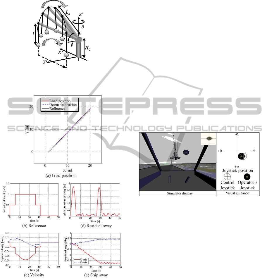
at the target position. By the result, it is clean that
control is well successful.
Figure 5: Concept of Straight Transfer Transformation
(STT).
Figure 6: Simulation result of STT with preshaping.
5 TEACHING TYPE TRAINING
SYSTEM BY INFORMATION
GUIDANCE
In this section, teaching method of sway suppression
proposed in last section is presented. In particular, we
have developed simulator as target that is an efficient
teaching for implicit knowledge.
5.1 Visual Information Teaching
In this section, a training system that converts control
input information to visual information and teaches it,
is proposed(Attir, 2006)(M.Radjaipour, 2005). This
system uses simulator display. We have paid attention
to the position of the joystick, and operating position
of the joystick is shown as a filled circle on the simula-
tor display (Fig. 7). In addition, a cross cursor shows
ideal position trajectory of the joystick. A horizontal
axis shows rotary angular velocity input and vertical
axis shows the boom luffing angular velocity. Con-
sidering the state of the load swing and rope motion
leads in the field of view, the visual guidance infor-
mation was arranged near the suspended load. Oper-
ator operates the joystick as tracking a filled circle to
a cross cursor. So, operator can easily replicate the
sway suppressing input.
Figure 7: Visual guidance training system.
The flow of this system is shown in Fig. 8. Block
diagram of the joystick maneuvered by operator is
shown the above diagram in Fig. 8. Diagram of the
joystick controlled is shown in the below side. Firstly,
the velocity input signal that is given by maneuver-
ing of operator is converted to angle information for
joystick. Next, angle information for joystick is con-
verted to visual information and it is outputted on the
simulator display. Indicating operation of the sway
suppressing, the information is outputted as joystick
that is maneuvered by operator. By outputting the
both simultaneously, training system by visual teach-
ing is built.
5.2 Haptic Information Teaching
In this part, haptic information teaching system using
active joystick is proposed. If operating angle of the
joystick deviates from ideal angle over certain angle,
active joystick feeds back force of correct angle to op-
DevelopmentofTrainingSimulatorforSwaySuppressionSkillsonShipboardRotaryCranes
437
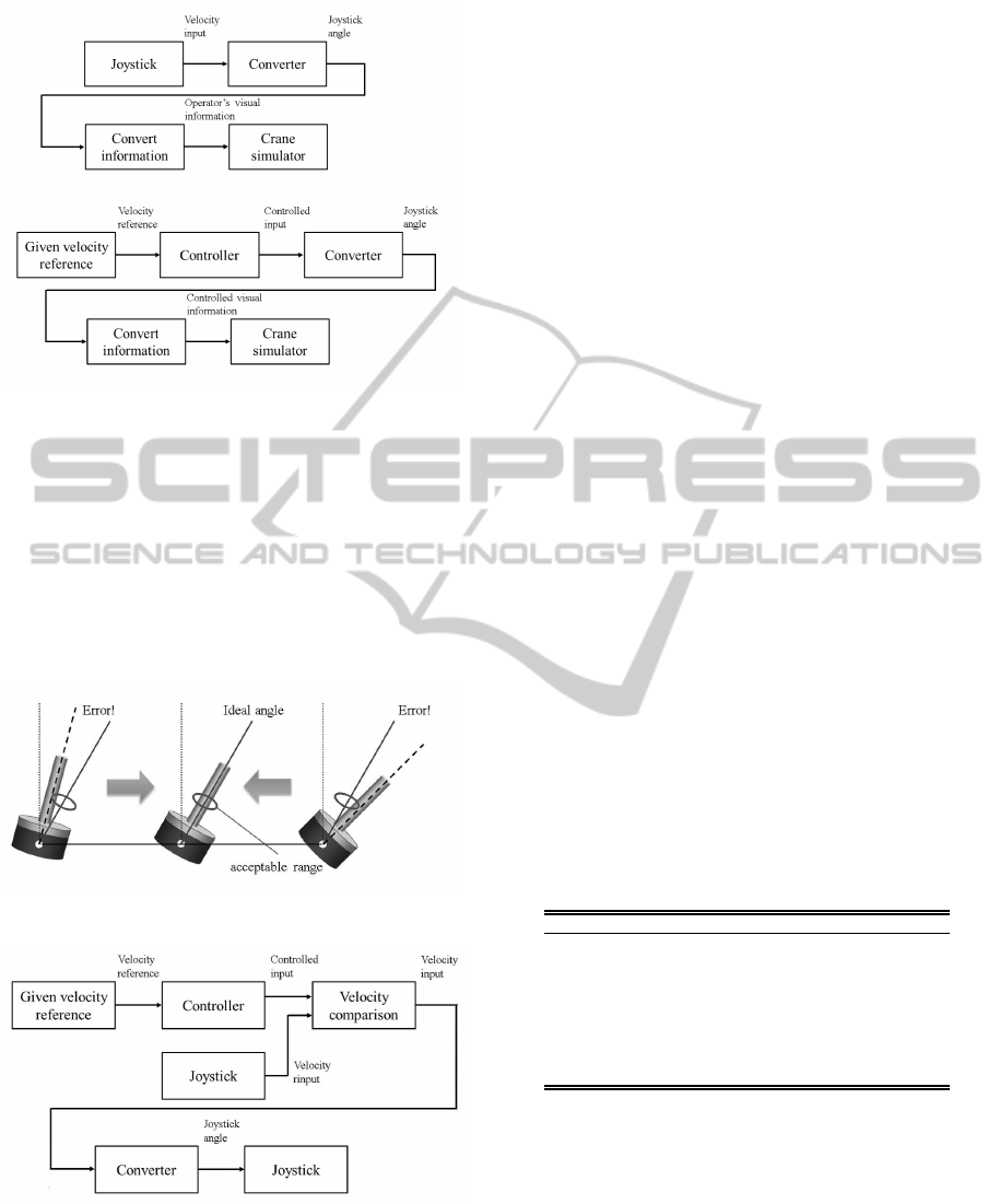
Figure 8: Block diagrams of visual teaching system.
erator’s hand (Fig. 9). Operator can spontaneously
train, when operated joystick receive force.
The flow of this system is shown in Fig. 10.
Firstly, sway suppression input that is obtained in ad-
vance and velocity input signal of the joystick that is
maneuvered by operator are compared. The force is
returned to operator by depending on the result of the
comparison. If needed, joystick angle is outputted and
force information is fed back to the joystick.
Figure 9: Active joystick motion of haptic teaching system.
Figure 10: Block diagram of haptic teaching system.
6 SIMULATION EXPERIMENTS
OF TRAINING
In this section, experiments for validity verification of
the training system are presented. In the experiments,
it conducted that transportation test in condition with-
out any teaching after training by the simulator.
6.1 Method of Experiment and
Evaluation
Simulation experiments were conducted for human
subjects of the following three groups. In addition,
human subjects were selected such as that initial op-
erating skill is almost equal condition.
• Group A (n = 3): Self training
• Group B (n = 3): Visual information teaching
• Group C (n = 3): Haptic information teaching
Here, parameter n is the number of human subject.
Firstly, transport test without teaching is conducted 3
times. Next, transport test is conducted 3 times after
3 times trainings and these are configured as 1 set.
Moreover, 1 set is conducted. Total 9 times trans-
port tests and 6 times trainings were conducted. Crane
specifications in the simulation are shown in Table 4.
Experimental content is transport to the target posi-
tion within 1.0 m with sway suppression. Considering
result of STT simulation (in section 4.3) and human
operating, and transport time in set to 35.0 sec. Eval-
uation items set as the absolute value of the residual
sway within allowable target position.
Table 4: Parameters of a crane for training use.
Parameter Symbol Value Units
Rope length l 30.0 m
Boom length L
B
37.0 m
Initial slew angle θ π rad
Initial Boom angle φ π/3 rad
Slew velocity input
˙
θ 0.00.1 rad/s
Boom velocity input
˙
φ 0.00.1 rad/s
Initial load position X,Y 1.5, 0.0 m
Target position X,Y 20.01.0, 18.51.0 m
6.2 Experimental Result
The mean of residual sway of each human subject is
shown in Fig. 11. Furthermore, result of subject (1)
of Group A in the 3rd set is shown in Fig. 12, result
of subject (4) of Group B in the 3rd set is shown in
Fig. 13 and result of subject (7) of Group C in the
3rd set is shown in Fig. 14. Residual sway of Group
A shows the increasing tendency or the decreasing
ICINCO2014-11thInternationalConferenceonInformaticsinControl,AutomationandRobotics
438
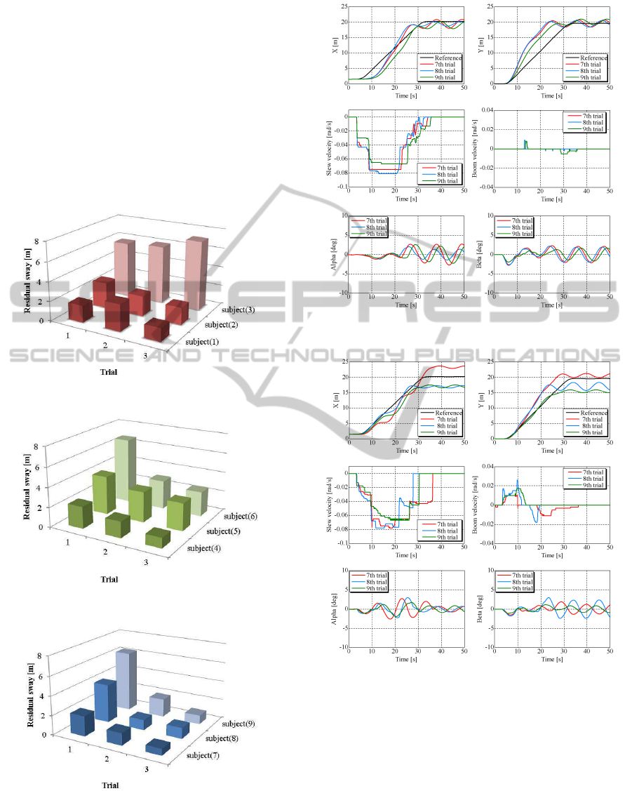
tendency. Self training doesn’t make constant train-
ing effect, because results of residual sway were var-
ied. On the other hand, all results of residual sway of
Group B and C are the decreasing tendency. Train-
ing effect is advanced by teaching system, and profi-
ciency of operating skill is notably appeared. In par-
ticular, haptic teaching system is the highest training
effect, because the mean of reduction rate of residual
sway is 70% in Group C. The reason is that operator is
sensuously able to acquire the operation of joystick by
active training, because both visual and haptic sense
are used in Group C.
(a) Group A
(b) Group B
(c) Group C
Figure 11: Training result of transfer process.
Figure 12: Training result of subject(1) in Group A.
Figure 13: Training result of subject(4) in Group B.
7 CONCLUSIONS
In this study, we built a virtual simulator to train sway
suppression skill in shipboard rotary crane. The re-
sults are as follows.
1. Movement of suspended load was reproduced by
3D model of shipboard rotary crane based on the
mathematical model.
2. Shipboard rotary crane was built by active joy-
DevelopmentofTrainingSimulatorforSwaySuppressionSkillsonShipboardRotaryCranes
439

Figure 14: Training result of subject(7) in Group C.
stick for the operation interface and 3D simulator.
3. Sway suppression control was adopted by pre-
shaping method, because control calculation is
simple.
4. Training system for teaching the operator was pro-
posed. The system presents operator both visual
information and haptic force for sway suppres-
sion.
5. Effectiveness of the training system was verified
by the results of training experiments using the
simulator.
REFERENCES
A.Tsutsui, M. (1998). Swing control for trolley cranes on
reclaiming ships. KOBE STEEL ENGINEERING RE-
PORTS, Vol.48(No.2):pp.18–21.
Attir (2006). Human operator performance testing using
an input-shaped bridge crane. Journal of Dynamics,
Measurement, Vol.8:pp.835–841.
Jiung Yao Huang, C. Y. G. (2003). Modelling and de-
signing a low-cost hight-fidelity mobile crane sim-
ulator. Int. Journal of Human-Computer Studies,
Vol.58(No.2):pp.151–176.
K.Watanuki, K.Kojima, K. (2007). Knowledge transfer
of crane operating skill on creating a mold using
portable vr system and force feedback device. Trans-
actions of the Japan Society of Mechanical Engineers
C, Vol.73(No.725):pp.53–58.
M.Kurimoto, H. (2009). Antisway control considering
phase of vibration of suspended load of a crane. Trans-
actions of the Japan Society of Mechanical Engineers
C, Vol.75(No.752):pp.858–864.
Mohammed F.Daqaq, A. H. (2003). Virtual reality simula-
tion of ships and ship-mounted cranes. Master thesis
of Virginia Polytechnic Institude and State University.
M.Radjaipour (2005). Human operator performance test-
ing using an input-shaped bridge crane. International
Journal of Occupational Medicine and Environmental
Health, Vol.8:pp.357–365.
N.Yong Jian, Y.Noda, K. (2011). Simulator building for
agile control design of shipboard crane and its appli-
cation to operational training. 18th World Congress of
the International Federation of Automatic Control.
R.Ito, K. (2009). Development of innovative integrated sim-
ulator on shipboard crane considering ship sway and
transfer control. Transactions of the Society of Instru-
ment and Control Engineers, Vol.45(No.12):pp.654–
663.
T.Iwasa, K.Terashima, N. and Y.Noda (2010). Operator as-
sistance system of rotary crane by gain-scheduled h-
inf controller with reference governor. 2010 IEEE
International Conference on Control Applications,
pages pp.1325–1330.
T.Sasaki, S.Fushimi, Y. J. N. and K.Terashima (2013).
Novel virtual training system to learn the sway sup-
pression of rotary crane by presenting ideal opera-
tion of joystick or visual information. 10th Interna-
tional Conference on Informatics in Control, Automa-
tion and Robotics.
ICINCO2014-11thInternationalConferenceonInformaticsinControl,AutomationandRobotics
440
