
Customised 3D Tooth Modeling by Minimally Invasive Imaging
Modalities
Sandro Barone, Alessandro Paoli and Armando Viviano Razionale
Department of Civil and Industrial Engineering, University of Pisa, Largo Lucio Lazzarino 1, 56126, Pisa, Italy
Keywords: Customised Tooth Reconstruction, Panoramic Radiograph, Discrete Radon Transform, Digital Cast.
Abstract: Dental panoramic tomography represents a standard imaging modality in dentistry since it provides a
convenient and inexpensive method to visualize anatomic structures and pathologic conditions with low
radiation doses. However, this technique does not provide comprehensive 3D geometries of dental shapes
which are conventionally demanded to computerised tomography (CT) techniques. In this paper, a tooth
reconstruction process is presented by integrating patient-specific information with general dental templates.
A 2D panoramic radiograph and the digitised patient plaster cast are used to customise both shape and
orientation of teeth templates thus allowing a consistent 3D tooth reconstruction with minimally invasive
imaging modalities. The proposed methodology does not make any assumption about the tomographic
device used to collect the panoramic radiograph.
1 INTRODUCTION
Orthodontics is the branch of dentistry concerned
with the study and treatment of irregular bites and
deals with the practice of manipulating patient
dentition in order to provide better functionalities
and appearances.
Detection and correction of malocclusion
problems caused by teeth irregularities and/or
disproportionate jaw relationships represent the most
critical aspects within an orthodontic diagnosis and
treatment planning. The most common
methodologies for non-surgical orthodontic
treatments are based on the use of fixed appliances
(dental brackets) or removable appliances (clear
aligners) (Kuncio et al., 2007). In clinical practice,
the conventional approach to orthodontic diagnoses
and treatment planning processes relies on the use of
plaster models of the patient’s mouth which are
manually analyzed and modified by clinicians in
order to simulate and plan corrective interventions.
These procedures however require labour intensive
and time consuming efforts which are mainly
restricted to highly experienced technicians. Recent
progresses in three-dimensional surface scanning
devices as well as CAD (Computer Aided
Design)/CAM (Computer Aided Manufacturing)
technologies have made feasible the complete
planning process within virtual environments and its
accurate transfer to the clinical field. In particular,
orthodontic alignment procedures greatly benefit
from the combined use of CAD/CAM
methodologies which are used to produce custom
tight-fitting devices worn by the patients (Boyd,
2007). In this context, the accurate and automatic
reconstruction of individual tooth shapes obtained
from digital 3D dental models is the key issue for
planning customized treatment processes. Optical
scanners may be used to digitize plaster models thus
providing geometric representations of tooth crowns.
However, even if both clear aligners and brackets
accomplish the treatment plan only by acting onto
the tooth crown surfaces, a correct orthodontic
treatment should also take into account tooth roots in
terms of position, shape and volume. In particular,
position and volume of dental roots may cause
dehiscence, gingival recession as well as root and
bone resorption when teeth undergo movements
during therapy. Cone beam computed tomography
(CBCT) can provide comprehensive 3D tooth
geometries. However, concerns about radiation
doses absorbed by patients are raised. For this
reason, the use of computed tomography as a routine
in orthodontic dentistry is still a matter of
discussion. Even if CBCT has greatly reduced the
dose of absorbed x-rays, compared to traditional
computed tomography (CT), it still produces a
greater x-ray dose than a panoramic radiograph
70
Barone S., Paoli A. and Razionale A..
Customised 3D Tooth Modeling by Minimally Invasive Imaging Modalities.
DOI: 10.5220/0004912400700075
In Proceedings of the International Conference on Bioimaging (BIOIMAGING-2014), pages 70-75
ISBN: 978-989-758-014-7
Copyright
c
2014 SCITEPRESS (Science and Technology Publications, Lda.)
(PAN).
2-D panoramic radiographs are a routine
approach in the field of dentistry since they
represent an important source of information. In
particular, they are able to inexpensively record the
entire maxillomandibular region on a single image
with low radiation exposure for the patient.
However, they are also characterised by several
limitations such as: lack of any 3D information,
magnification factors which strongly vary within the
image thus causing distortions, patient positioning
which is very critical with regard to both sharpness
and distortions. As a result, not only 3D
measurements are impaired, but also reliable 2D
dimensions cannot be retrieved.
The present paper is aimed at investigating the
possibility to recover 3D geometry of individual
teeth by customising general templates over patient-
specific dental anatomy. Information about patient
anatomy is obtained by integrating the optical
acquisition of plaster casts with 2D panoramic
radiographs. Even if the reconstruction of patient-
specific 3D dental information from 2D radiographs
and casts represents a challenging issue, very few
attempts have been made up to now within the
scientific community (Pei et al., 2012, Mazzotta et
al., 2013). Moreover, these studies greatly rely on
the knowledge of the specific tomographic device
used to acquire the PAN image. The present study is
focused on the formulation of a general solution
which could infer tooth roots shape without any
assumption on the specific hardware as well as
parameters used to collect patient data anatomy.
2 MATERIALS AND METHODS
In this paper, whole 3D teeth shapes are
reconstructed by integrating template models with
3D crowns data deriving from the optical acquisition
of plaster casts and 2D data deriving from PAN
radiographic images.
An optical scanner based on a structured light
stereo vision approach has been used to reconstruct
both template dental models and patient’s dental
casts.
Panoramic radiographs have been captured by
using a Planmeca ProMax unit (Planmeca Oy,
Helsinki Finland); whose data are stored and
processed in DICOM format.
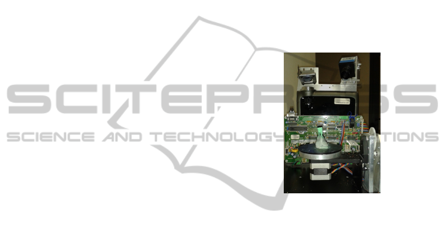
2.1 3D Data Acquisition System
The optical scanner (Figure 1) is composed of a
monochrome digital CCD camera (1280 × 960
pixels) and a multimedia white light DLP projector
(1024 × 768 pixels) which are used as active devices
for a stereo triangulation process. In this paper, a
multi-temporal Gray Code Phase Shift Profilometry
(GCPSP) method is used for the 3D shape recovery
through the projection of a sequence of black and
white vertical fringes whose period is progressively
halved (Barone et al., 2013). The methodology is
able to provide n
p
= l
h
× l
v
measured points (where l
h
is the horizontal resolution of the projector while l
v
is the vertical resolution of the camera) with a spatial
resolution of 0.1 mm and an overall accuracy of 0.01
mm.
Figure 1: Optical scanner during the acquisition process of
a tooth template.
The optical devices are integrated with two
mechanical turntables (Figure 1) which allow the
automatic merging of different measurements
collected from various directions conveniently
selected.
2.2 Input Data
The methodology requires three different input data:
1) general dental CAD templates, 2) dental crowns
shape and 3) a PAN image. Crowns shape and PAN
image are patient-specific data while teeth templates
can be obtained from existing libraries.
2.2.1 Dental CAD Templates
Teeth template models are composed of complete
teeth crowns and roots and are placed in adequately
shaped holes within transparent plastic soft tissue
reproduction (Figure 2). Teeth can be easily
removed from their housing in order to allow full
reconstructions through the 3D scanner without
optical occlusions.
Customised3DToothModelingbyMinimallyInvasiveImagingModalities
71
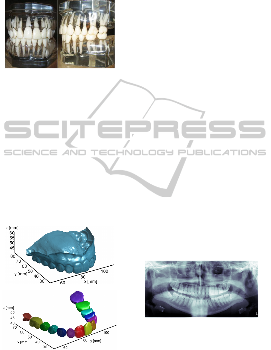
Figure 2: Example of superior and inferior dental arch
templates.
2.2.2 Patient Crowns Reconstruction
The patient dental crowns geometry can be acquired
by scanning the plaster cast. Figure 3a shows the
final digital reproduction of the patient tooth crowns
with surrounding gingival tissue (digital mouth
model) as obtained by merging twelve acquisitions
of the superior plaster cast captured by different
views. Tooth crown regions are segmented and
disconnected from the oral soft tissue by exploiting
the curvature of the digital mouth model. This model
contains ridges and margin lines, which highlight the
boundaries between different teeth, and between
teeth and soft tissue. Regions with abrupt shape
variations can be outlined by using curvature
information (Barone et al., 2013). Segmented crown
shapes are finally closed by using computer-based
filling tools (Figure 3b).
(a)
(b)
Figure 3: (a) Reconstruction of the superior plaster cast as
obtained by the optical scanner and (b) segmented patient
crowns geometries.
2.2.3 Panoramic Radiograph
Dental panoramic systems provide comprehensive
and detailed views of the patient maxillo-mandibular
region by reproducing both dental arches on a single
image film (Figure 4).
A panoramic radiograph is acquired by
simultaneously rotating the x-ray tube and the film
around a single point or axis (rotation centre). This
process, which is known as tomography, allows the
sharp imaging of the body regions disposed within a
3D horseshoe shaped volume (focal trough or image
layer) while blurring superimposed structures from
other layers. The rotation centre changes as the film
and x-ray tube are rotated around the patient’s head.
Location and number of rotation centres influence
both size and shape of the focal through which is
therefore designed by manufacturers in order to
accommodate the average jaw.
2.3 Methodology
The proposed methodology is based on scaling the
tooth CAD template models accordingly to the
information included within the patient segmented
tooth crowns shape and the PAN image.
Segmented crown models are used to determine
the axis of each patient tooth. Teeth templates are
then linearly scaled by using non-uniform scale
factors along three different dimensions (Figure 5).
In particular, the tooth width (taken along the
mesiodistal line) and the tooth depth (taken along
the vestibulo-lingual direction) values are directly
determined from the patient crown geometries. The
tooth height (taken along the vertical direction of the
panoramic radiograph) is rather estimated by using
the PAN image.
Figure 4: Panoramic (PAN) radiograph.
The height estimation process, which represents the
core of the proposed method, is based on the
reconstruction of a synthetic PAN image from the
3D patient crowns geometries. A panoramic
radiograph essentially represents the sum of x-ray
attenuation along each ray transmitted from the
BIOIMAGING2014-InternationalConferenceonBioimaging
72
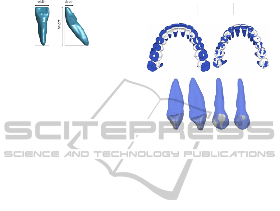
Figure 5: Tooth dimensions used to scale CAD templates.
source to the film (Tohnak et al., 2006). The
attenuation is due to the x-ray absorption by tissues
along the ray. For this reason, it is possible to
emulate a panoramic radiograph by taking 2D
projections through a data volume. In this paper, the
Discrete Radon Transform (DRT) is used to
calculate finite pixel intensity sums along rays
normal to a curve which approximate the medial
axis of the crowns arch.
The whole methodology can be summarized in
the following steps:
Uniform scaling of the complete dental
template arch by using the patient digitised
cast (Figure 6a);
Alignment of each tooth template on the
corresponding patient tooth crown geometry
in order to determine the orientation and
position with respect to the bone structure;
Non-uniform scaling by using the tooth width
and depth values (Figure 6b);
Tooth height estimation from the PAN image
by simulating the panoramic radiograph
process through the Discrete Radon
Transform applied on the reconstructed patient
crowns model.
The first three steps are quite straightforward and
can be accomplished by using any CAD software.
The last step is fully detailed in the following
section.
2.3.1 Tooth Height Estimation
The 3D patient crowns model must be spatially
oriented, by a rigid motion, in order to make its
projection consistent with the corresponding crowns
region in the PAN radiograph.
A set of n corresponding markers [P
i
PAN
(x
i
PAN
, y
i
PAN
,
z
i
PAN
), P
i
cr
(x
i
cr
, y
i
cr
, z
i
cr
)] is interactively selected on
crown regions of both PAN image and segmented
crowns model. A rigid motion, applied to the 3D
model and described by a rotation matrix (R) and a
translation vector (T), is then determined by
minimising an objective function defined as:
2
1
(,)
n
ii
P
AN cr
i
fRT z z
(1)
(a)
(b)
Figure 6: (a) Uniform scaling of the complete dental
template arch and (b) two examples of non-uniform tooth
scaling by using width and depth values.
This transformation guarantees the alignment
between the 3D patient crowns model and the
radiograph along the z-direction (Figure 7). A
further transformation is then required in order to
project the 3D model onto the panoramic image.
This process is accomplished by computing multiple
parallel-beam projections, from different angles,
using the DRT. In particular, a 2D image is firstly
created by projecting the crowns model onto the X
cr
-
Y
cr
plane (Figure 8). A fourth order polynomial
curve (
) is then determined by interpolating the
projection of the selected P
i
cr
(x
i
cr
, y
i
cr
) points.
The 3D model is vertically sliced with the same
vertical resolution of the PAN image. For each
horizontal slice, crown contours are projected along
the direction normal to
in correspondence of each
curve point by using the DRT (Figure 8). The curve
point sampling (s
i
) is piecewisely estimated by
matching the number of samples between two
consecutive P
i
cr
points with the number of pixels
along the X
PAN
direction between the corresponding
P
i
PAN
points. Figure 9a shows the DRT results for the
projection of the crowns model illustrated in Figure
3b, while Figures 9b and 9c show its
superimposition on the original PAN image.
Tooth heights are then extracted from the PAN
image by the selection of root tips which are back-
projected onto the 3D model. This back-projection is
performed by considering the coordinates of the root
tip in the PAN image. The z-coordinate, up to a scale
Customised3DToothModelingbyMinimallyInvasiveImagingModalities
73
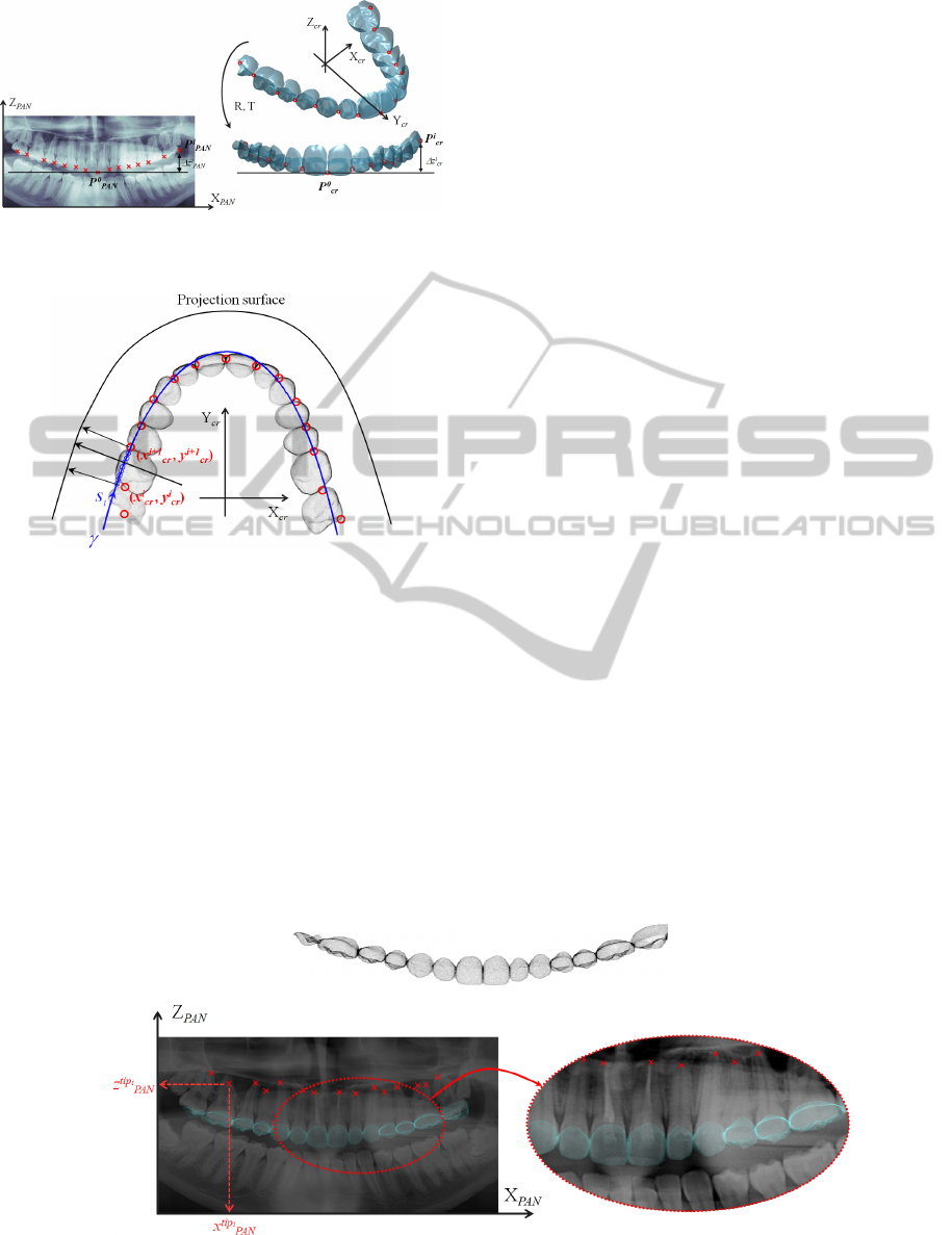
Figure 7: Alignment between 3D crowns model and PAN
image along the z-direction.
Figure 8: Projection scheme of the 3D patient crowns
model.
factor, is used to identify the slice to which the 3D
root tip belongs:
i
i
tip
tip
cr z
PAN
zscalez
(2)
The x-coordinate is instead used to retrieve the
curvilinear coordinate along the
curve by:
i
i
tip
tip
PAN
sx
(3)
The line normal to
and passing from s
tip
i
describes the projection ray through the root tip. It is
then possible the spatial identification of a direction
on which the 3D root tip must certainly lie
(constraint line). The template tooth model, already
scaled by considering width and depth values can
then be finally scaled along the height direction in
order to approach the above outlined constraint line.
Clearly, an indetermination about the root
inclination still remains since the tooth root could be
indifferently oriented to the buccal or lingual side of
dentition. However, the preventive alignment of the
tooth template on the patient crown model should
guarantee the correct orientation of the reconstructed
tooth.
3 PRELIMINARY RESULTS
The feasibility of the proposed methodology has
been verified by reconstructing some teeth of a
female patient superior dental arch. Figure 10 shows
two views of the CAD templates aligned and scaled
(using tooth width and depth values) on the crowns
model, along with the directions on which respective
root tips should lie. CAD templates are then further
scaled along the tooth heights while tooth axes are
oriented in order to intersect the respective
constraint lines (Figure 11). Crown geometries,
acquired by the optical scanner, and root geometries,
estimated by scaling CAD templates, are then
merged together thus creating the final digital tooth
model (Figure 12).
The reconstructed tooth shapes can be compared
to those obtained by processing volumetric data
from patient CBCT scans. In this case, segmented
tooth geometries from CBCT data (Figure 13a) can
be used as ground truth to assess the accuracy of 3D
models reconstructed by using minimally invasive
imaging modalities (Figure 13b,c).
(a)
(b) (c)
Figure 9: (a) DRT projection of the 3D patient crowns model, (b) superimposition of the projection on the PAN image
along with a detail (c). The crowns model projection is highlighted with a transparent cyan colour.
BIOIMAGING2014-InternationalConferenceonBioimaging
74
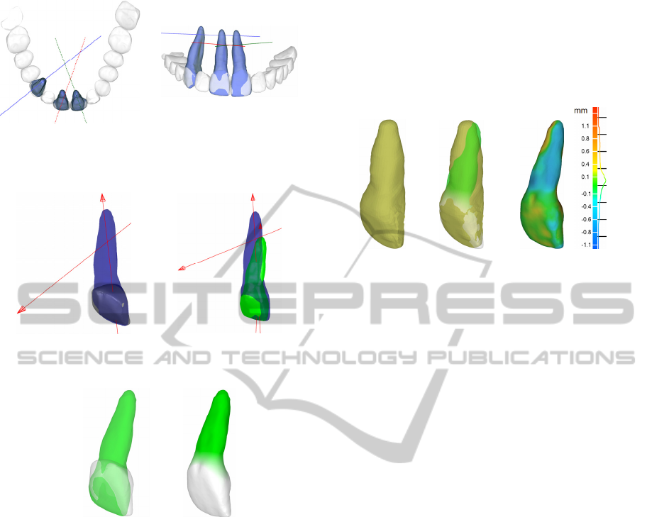
Figure 10: CAD templates aligned and scaled on the
crowns model with the respective constraint lines for root
tips.
Figure 11: Final height scaling and orientation (green
model) of the tooth CAD template (blue model).
Figure 12: Merging between crown geometry (gray
model) and scaled tooth CAD template (green model).
4 CONCLUSIONS
In the field of orthodontic dentistry, one of the main
challenges relies on the accurate determination of
3D dentition geometries by exposing the patient to
the minimum radiation dose. In this context, the
present paper outlines a methodology to infer 3D
shape of tooth roots by combining the patient digital
plaster cast with a panoramic radiograph. The
method investigates the possibility to adapt general
dental CAD templates over the real anatomy by
exploiting geometrical information contained within
the panoramic image and the digital plaster cast. The
proposed modelling approach, which has showed
encouraging preliminary results, allows a
generalised formulation of the problem since
assumptions about the tomographic device used for
radiographic data capturing are not required.
Many are the variables involved in the adopted
formulation. In particular, key issues are represented
by the optimization of the
curve, whose slope
determines the orientation of root tip constraint
lines, and the accurate evaluation of magnification
factors along the z-direction of the PAN image.
(a) (b) (c)
Figure 13: (a) CBCT tooth ground truth, (b) overlapping
between CBCT and reconstructed tooth model, (c)
discrepancies between the two models.
These topics certainly require further research
activities taking also into account, for example,
additional information which could be extracted by
supplementary lateral radiographs.
REFERENCES
Barone, S., Paoli, A. & Razionale, A. 2013. Creation of
3D Multi-Body Orthodontic Models by Using
Independent Imaging Sensors. Sensors, 13, 2033-
2050.
Boyd, R. L. 2007. Complex orthodontic treatment using a
new protocol for the Invisalign appliance. Journal of
Clinical Orthodontics, 41, 525-547.
Kuncio, D., Maganzini, A., Shelton, C. & Freeman, K.
2007. Invisalign and traditional orthodontic treatment
postretention outcomes compared using the American
Board of Orthodontics Objective Grading System.
Angle Orthodontist, 77, 864-869.
Mazzotta, L., Cozzani, M., Razionale, A., Mutinelli, S.,
Castaldo, A. & Silvestrini-Biavati, A. 2013. From 2D
to 3D: Construction of a 3D Parametric Model for
Detection of Dental Roots Shape and Position from a
Panoramic Radiograph—A Preliminary
Report. International Journal of Dentistry, 2013, 8.
Pei, Y. R., Shi, F. H., Chen, H., Wei, J., Zha, H. B., Jiang,
R. P. & Xu, T. M. 2012. Personalized Tooth Shape
Estimation From Radiograph and Cast. IEEE
Transactions on Biomedical Engineering, 59, 2400-
2411.
Tohnak, S., Mehnert, A., Crozier, S. & Mahoney, M.
2006. Synthesizing panoramic radiographs by
unwrapping dental CT data. 2006 28th Annual
International Conference of the IEEE Engineering in
Medicine and Biology Society, Vols 1-15, 1484-1487.
Customised3DToothModelingbyMinimallyInvasiveImagingModalities
75
