
Hinged External Fixators for Knee Rehabilitation
Kinematic Concept of a Two Degree-of-Freedom System
Gianluca Gatti
1
, Shadi Shweiki
1
, Giorgia Lupinacci
1
, Gionata Fragomeni
2
and Guido Danieli
1
1
Dept. of Mechanical, Energy and Management Engineering, University of Calabria, V. Bucci, 87036 Rende (CS), Italy
2
Dept. of Medical and Surgical Sciences, University of Magna Graecia, V. Europa, 88100 Catanzaro (CZ), Italy
Keywords: Knee Kinematics, Passive Knee, Hinged External Fixator, Knee Dislocation.
Abstract: Hinged external fixators are used in knee dislocation treatment, where they have shown their effectiveness.
They are proposed as a technique to protect ligament reconstructions while allowing early postoperative
rehabilitation. A hinged external fixator usually consists of two rigid links connected to each other by a
revolute joint. Each link is then fixed to the femur and tibia, via direct pin fixation. A single-axis hinged
external fixator thus well accommodates the main knee movement, i.e. the flexion and extension. This paper
presents an investigation on the conceptual idea of a double-axis hinged external fixator for the human knee,
which accommodates for both flexion-extension and longitudinal internal-external rotation of the tibia
respect to the femur. The potential advantage of such a design is foreseen in the increasing range of motion
in postoperative knee rehabilitation and a better accommodation of natural knee motion.
1 INTRODUCTION
Injuries and trauma that may occur in the human
knee often lead to difficulties in having a fast and
complete rehabilitation. Among these trauma,
dislocation is one of the most severe injuries.
Clinical outcomes after knee dislocations are
frequently unsatisfactory, and pain, instability and
arthrofibrosis are the most frequent complications
(Stannard et al., 2003; Stayner and Coen, 2000). The
instability basically lies in the injury of ligaments,
and in some cases, even after repair, there is
insufficient stability for early rehabilitation. This is
the reason why preliminary reports on such
treatment focused on achieving stability of the
ligaments by means prolonged immobilisation
during the postoperative period, although this would
lead to stiffness of the joint (Noyes and Barber-
Westin, 1997; Shapiro and Freedman, 1995).
In more recent studies, authors intensely
advocate early and aggressive mobility despite the
risk of ligament repair or reconstruction failing
(Cole and Harner, 1999; Yeh et al., 1999), and this
led to the concept of the fixator with motion
capabilities (Deszczynski et al., 2000; Fitzpatrick et
al., 2005). A hinged external fixator usually consists
of two rigid links connected to each other by a
revolute joint. Each link is fixed to the femur and
tibia through direct pin fixation. Previous
biomechanical studies showed that a single-axis
hinged external fixator is able to reproduce and
accommodate the normal knee kinematics in a
limited portion of the range of motion without
harmfully loading the structures (Sommers et al.,
2004; Wroble et al., 1997). Such external hinge, set
to an approximate rotational axis of the articular
joint, neutralises the displacing forces during the
movement, and control the natural repair mechanism
of the ligament apparatus. The fixator will thus
allow patient mobility without the risk of loading the
injured area during treatment and rehabilitation.
The main difficulty in the application of hinged
external fixators is the implantation and, in
particular, the location of the articular joint axis of
rotation. Commonly, this axis is manually identified
by means of radiographs on the base of bony
landmarks (Fragomeni et al., 2006; Richter and
Lobenhoffer, 1998) and then the mechanical hinge
of the fixator is aligned through screw adjustments.
This technique may be prone to errors and the
approximation in enforcing an articular joint to an
unnatural mechanical behaviour may lead to
unwanted outcomes in post-traumatic knee
kinematics. This latter is, in fact, a result of a
224
Gatti G., Shweiki S., Lupinacci G., Fragomeni G. and Danieli G..
Hinged External Fixators for Knee Rehabilitation - Kinematic Concept of a Two Degree-of-Freedom System.
DOI: 10.5220/0004904002240229
In Proceedings of the International Conference on Biomedical Electronics and Devices (BIODEVICES-2014), pages 224-229
ISBN: 978-989-758-013-0
Copyright
c
2014 SCITEPRESS (Science and Technology Publications, Lda.)
complex interaction of bones, ligaments and
muscles, which may be completely described by six
degrees of motion during dynamic activities
(Palastanga et al., 1989; Lafortune et al., 1992).
Only as a first approximation, such kinematics may
be modelled as a simple flexion-extension
movement, which is indeed coupled to the
longitudinal rotation of the tibia (Piazza and
Cavanagh, 2000), making knee kinematics three-
dimensional.
In this paper, we present the conceptual idea of a
two degree-of-freedom (DOF) system from the
kinematic point of view, which may cope with both
the two dominant movements of the knee, i.e. the
flexion-extension (FE) and the longitudinal internal-
external rotation (LR). The aim of the paper is
mainly to show the most relevant kinematic issues
involved in such a design. As such, some of the
forthcoming issues related to the materials selection,
and to the specific fastening and assembling
considerations are not treated in the following
sections.
Such a device design would potentially allow for
a better rehabilitation, while retaining the main
advantages of articulated external fixation. And this
would be due to the fact that an additional degree of
mobility, respect to traditional hinged fixators,
would allow the articular knee joint to better
accomplish its natural movement
.
2 MATERIALS & METHODS
2.1 Knee Joint Axes Identification
Design and implant of hinged external fixators
requires a good understanding ok knee kinematics
and accurate measurements. Among the different
techniques effectively used for joints kinematics
detection, relying on electromagnetic, imaging or
ultrasound systems (Kinzel and Gutkowski, 1983;
Bull and Amis, 1998), instrumented spatial linkages
(ISLs) are perhaps some of the most commonly used
6-DOF measuring devices for anatomical joints
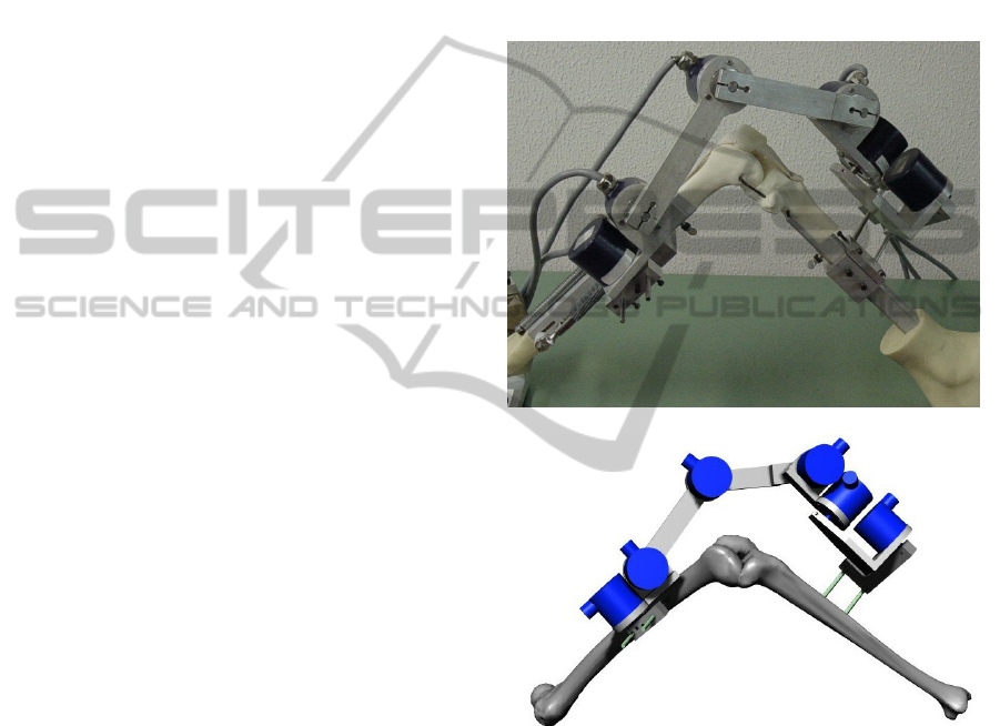
motion description. An application of an ISL in
place on a MITA Endo Leg system and on a virtual
knee model is reported in Figure1(a) and (b).
An ISL consists of a series of seven rigid links
connected to each other by six rotational sensors.
The end segments of the ISL are attached to the two
bones whose relative motion is to be measured, and
this motion can be estimated by the geometry of the
linkage and the transducers reading. The use of ISLs
to measure three-dimensional human joints motion
were effectively applied for either in vitro or in vivo
studies (Lewandowski et al., 1997; Van Sint Jan et
al., 2002), and also effectively used whenever direct
fixation to bones is required (Gardner et al., 1996;
Danieli et al., 2005a; Ishii et al., 1997), as an
alternative approach to active robotic systems
(Danieli et al., 2005b). Requirements for adequate
measurements involve advanced calibration of the
devices (Liu and Panjabi, 1996; Gatti et al., 2010;
Gatti and Danieli, 2008; Sholukha et al., 2004; Gatti
and Danieli, 2007).
(a)
(b)
Figure 1: An application of an ISL to measure knee
kinematics of (a) a MITA Endo Leg System and (b) a
virtual knee model.
Several authors (Hollister et al., 1993; Roland et
al., 2010; Gatti, 2012), presented and validated
techniques to estimate and identify both the
functional FE axis and the LR axis of the human
knee. Experimental clinical outcomes based on
literature, e.g. Smith et al. (2003) and Williams and
Logan (2004), may be also used as a guide to
correctly identify the location of knee axes and help
in correctly setting the external fixator implant.
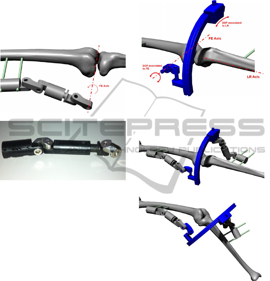
With reference to Figure 2, for instance, the
HingedExternalFixatorsforKneeRehabilitation-KinematicConceptofaTwoDegree-of-FreedomSystem
225

technique presented in (Gatti, 2012) let one define
the FE axis by identifying the components of its unit
vector u
F
and the coordinates of a point O
F
in an
orthogonal reference frame (x
B
,y
B
,z
B
) attached to the
femur. In a similar way, the LR axis is defined by
identifying the components of its unit vector u
R
and
the coordinates of a point O
R
in an orthogonal
reference frame (x
E
,y
E
,z
E
) attached to the tibia. These
geometrical features are easily identified when using
an ISL with its end fixtures attached rigidly to the
proximal and distal bones.
Figure 2: Identification of the dominant axes of the knee
joint according to the procedure described in (Gatti, 2012).
Although these techniques appear to be applied
to virtual models, and clinical applications to
cadaveric knee specimens seems not to be reported
yet, they seem to be potentially applicable in
experimental campaigns on in-vitro fresh-frozen
cadaveric specimens to clinically identify the
approximate location of the two dominant axes with
respect to specific bony landmarks.
2.2 External Fixator Kinematics
Once the approximate FE axis and the LR axis are
identified, an articulated hinged external fixator with
two degrees of freedom, i.e. having two rotational
hinges, may be designed having its mechanical
hinge joints aligned to the functional knee axes, in a
similar manner than that currently suggested in the
recommended technique and instructions by
manufacturers of single-axis hinged external fixators
(e.g. Compass Universal Hinge, Smith&Nephew).
In order to allow for an accurate alignment, the
kinematic structure of the 2-DOF external fixator
should be designed properly, such to have the
capability to set the correct position and orientation
of each functional axis respect to the relative bone.
This can be assured by the use of a multi-DOF
adjustable kinematic structure which is attached at
one end to the fixation pins of the correspondent
bone, and at the other end is aligned to the
correspondent functional axis. The kinematic
structure reported in the schematics of Figure 3,
illustrates these requirements. In this figure,
different mechanical joints are identified by different
letters, where R stands for ‘rotational’ joint, which
allows only a relative rotation to its joined links
around its axis of rotation, and C stands for
‘cylindrical’ joint, which allows for simultaneous
independent rotation and translation of its joined
links around and along its axis of motion. As a
whole, the kinematic chain reported in Figure 3, has
three rotational joints each allowing for one relative
DOF and two cylindrical joints, each allowing for
two relative DOF – it then has a total of one DOF
which is uses to adjust the kinematic structure
according to the bone segment.
Figure 3: Schematics of the multi-DOF kinematic
structure to allow for alignment of the functional FE axis.
An equivalent structure is used, respect to the tibia, to
allow for alignment of the functional LR axis.
Once each functional axis is identified in its
correspondent reference frame, the multi-DOF
structure, as sketched in Figure 3, may be used to set
the correct alignment both in position and
orientation.
The coupling between the two structures is then
realized by designing a two DOF mechanism which
allows for free independent rotations around the two
functional axes of the knee joint. This is illustrated
in the sketch of Figure 4.
Figure 4: Schematics of the 2-DOF mechanism to allow
for independent rotations around the two functional axes
of the knee joint.
The mechanism is realized by assembling three
cylindrical joints to assure a fixed orientation
between the two functional knee joint axes.
BIODEVICES2014-InternationalConferenceonBiomedicalElectronicsandDevices
226
The mechanical assembly sketched in Figure 3 may
be realized by connecting standard fixator
components. A virtual CAD model of the proposed
multi-DOF structure is illustrated in Figure 5(a),
while a photograph of the correspondent standard
component assembly is shown in Figure 5(b).
(a)
(b)
Figure 5: Multi-DOF structure used to assure correct
position and orientation of functional joint axis respect to
the correspondent bone: (a) virtual CAD model and (b)
photograph of an assembly using standard fixator
components.
From the mechanical point of view, the 2-DOF
mechanism sketched in Figure 4 presents an issue
related to the fact that it is not possible to align a
mechanical joint to the LR axis since it is located
internally to the shank. This is overcome by
designing an equivalent mechanism, whose virtual
CAD model is shown in Figure 6. In this assembly
the DOF associated to the FE rotation is realized by
the use of a hinge joint located externally to the
knee, while the DOF associated to the LR rotation is
realized by the use of a circular ring coupled to a
mating feature which realizes an equivalent
rotational motion without the need of physically
locating a mechanical hinge on the LR axis. The full
virtual assembly of the external fixator, with the
multi-DOF structures connected to the 2-DOF
mechanism is illustrated in Figure 7.
The 2-DOF hinged external fixator is then
designed so that it may be correctly implanted once
the relative location and orientation of the two
Figure 6: Virtual CAD model of the 2-DOF mechanism
used to assure free independent rotations around the two
functional axis of the knee joint.
(a)
(b)
Figure 7: Virtual CAD model of the whole 2-DOF hinged
external fixator implanted to a virtual knee model: (a)
assembly in the full extended configuration with no LR
rotation, and (b) assembly in a configuration such that the
angle of flexion is about 45° relative to the configuration
in (a), and the angle of longitudinal rotation is
approximately 5° relative to the configuration in (a).
functional knee joint axes are identified by the use of
an ISL. The fixation pins on each bone segment
assure that both the ISL and the external fixator have
a unique reference frame association, so that errors
HingedExternalFixatorsforKneeRehabilitation-KinematicConceptofaTwoDegree-of-FreedomSystem
227
may be reduced at source. The multi-DOF structures
are cinematically designed so has to allow for a
proper degree of mobility in order to set the
clamping fixture on the fixation pins according to
the specific thigh/shank conformation. Once each
multi-DOF structure is adjusted to correctly match
the correspondent functional axis, each joint of the
structure is locked using the screw connections
adopted in standard fixators, as shown in Figure
5(b). This assures that the relative position and
orientation of the functional axes remain constant
throughout the knee joint motion.
Simulations are finally performed on a virtual
model of the knee as illustrated in Figure 7,
assuming fixed axis of FE and fixed axis of LR. To
account for a more general case, the functional axes
are chosen neither to be orthogonal nor to intersect
each other. More specifically, a simulation is run by
assuming, with reference to Figure 2, the following
location for the functional FE axis
B
O
F
= (190, 80, -
10) mm,
B
u
F
= (0.1219, 0.9775, 0.1724) and the
following location for the functional LR axis
E
O
F
=
(16.068, -107.57, 139.52) mm,
E
u
F
= (0.0733,
0.9779, 0.1956), where the superscript on the left-
hand side denotes the frame of reference respect to
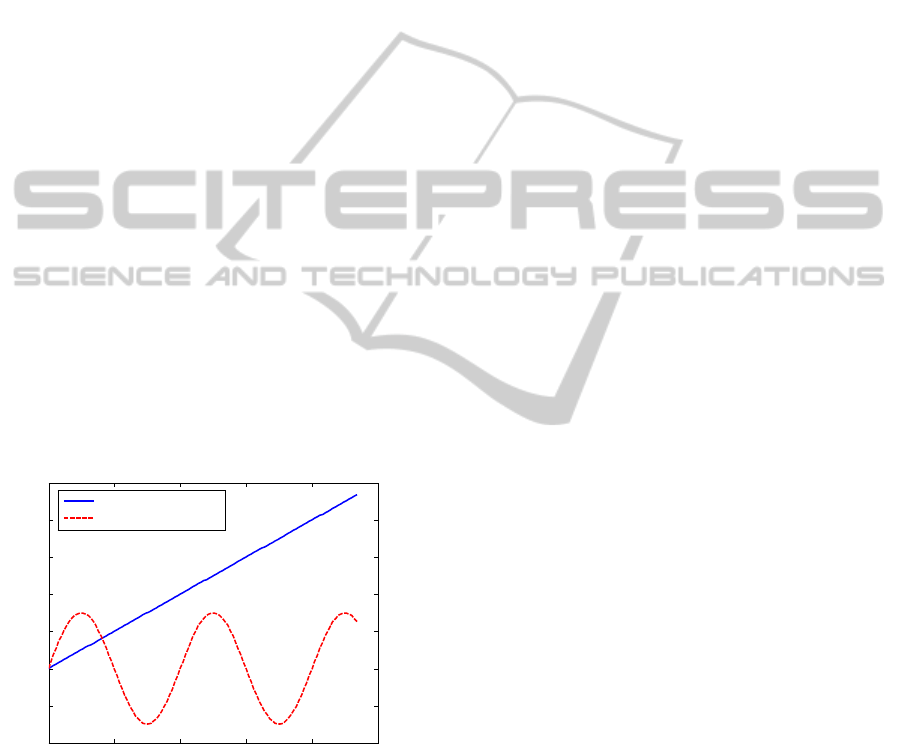
which coordinates are given. The angle of flexion
and longitudinal rotation are varied according to the
plot in Figure 8. The simulations performed
confirmed the validity of the kinematic solution
proposed in the paper.
Figure 8: Angles of flexion-extension and longitudinal
rotation imposed in simulation.
3 CONCLUSIONS
The conceptual idea of a double-axis hinged
articulated external fixator with two degrees of
freedom is illustrated in this paper. Such a system is
based on clinical findings which shows that, in the
human knee motion, the flexion extension
movement is coupled with a longitudinal internal-
external rotation of the tibia. In knee dislocations
treatments, where aggressive mobility and
rehabilitation is advocated, such a biomechanical
devices could potentially improve the motion
capabilities currently provided by available single-
axis external fixators, and hopefully improve
postoperative outcomes for patients. The current
work limited the presentation to the kinematic
design and conceptualization of the fixator. As such,
the mobility of the device, its degree of adjustment
according to patient, and its main kinematic issues
have been addressed. Kinematic simulations have
been performed to assess the validity of the design.
The main fixator components are those used in other
standard fixators, so that the design of specific
features is only limited to the innovative parts
achieving the double-axis movement. Comparative
analyses with other fixators is foreseen, and
extensions of the present work will include also an
insight into the manufacturing issues, strength
requirements and material selection. A preliminary
prototype of the proposed external fixator is planned
to be realized and applied to a physical model of the
knee joint available in laboratory, once its functional
axes have been estimated by the use of the available
ISL using the procedures described in the literature.
REFERENCES
Bull, A. M. J., Amis, A. A., 1998. Knee joint motion:
description and measurement. Proceedings of the
Institution of Mechanical Engineers Part H—Journal
of Engineering in Medicine 212:357-372.
Cole, B. J., Harner, C. D., 1999. Complex topics in knee
surgery: The multiple ligament injured knee. Clinics in
Sports Medicine 18:241-262.
Danieli, G. A., Fragomeni, G., Gatti, G., Moschella, D.,
2005. Enhanced reality representation of a fracture
reduction process using external fixation. WSEAS
Transactions on Systems 4:1087-1095.
Danieli, G. A., Fragomeni, G., Gatti, G., Merola, A.,
Moschella, D., 2005. Navi-robot, a navigator able to
turn itself into a robot to reach the correct position for
a given task during orthopaedic surgical procedures.
WSEAS Transactions on Systems 4:1037-1045.
Deszczynski, J., Szczesny, G., Karpinski, J., 2000. Use of
the Dynastab-K (knee) external fixator technique for
functional treatment of intra- and peri-articular
fractures of the knee joint. Chir Narzadow Ruchu
Ortop Pol. 65:409-415.
Fitzpatrick, D. C., Sommers, M. B., Kam, B. C. C., Marsh,
J. L., Bottlang, M., 2005. Knee stability after
articulated external fixation. American Journal of
0 50 100 150 200 250
-20
-10
0
10
20
30
40
50
Angle (deg)
Simulation frame
Flexion-extension
Longitudinal rotation
BIODEVICES2014-InternationalConferenceonBiomedicalElectronicsandDevices
228

Sports Medicine 33:1735-1741.
Fragomeni, G., Mundo, D., Gatti, G., Moschella, D.,
Danieli, G. A., 2006. Preliminary design of a knee
external fixator based on planar geometric synthesis.
Transactions of the Canadian Society for Mechanical
Engineering 30:567–579.
Gardner, T. N., Evans, M., Kyberd, P. J., 1996. An
instrumented spatial linkage for monitoring relative
three-dimensional motion between fracture fragments.
Journal of Biomechanical Engineering 118:586–594.
Gatti, G., Danieli, G., 2007. Validation of a calibration
technique for 6-DOF instrumented spatial linkages.
Journal of Biomechanics, 40:1455–1466.
Gatti, G., Danieli, G., 2008. A practical approach to
compensate for geometric errors in measuring arms:
Application to a six-degree-of-freedom kinematic
structure. Measurement Science and Technology 19:
015107.
Gatti, G., Mundo, D., Danieli, G., 2010, Kinematic
analysis and performance evaluation of 6R
instrumented spatial linkages. Transactions of the
Canadian Society for Mechanical Engineering 34: 57-
73.
Gatti, G., 2012. On the estimate of the two dominant axes
of the knee using an instrumented spatial linkage,
Journal of Applied Biomechanics 28:200-209.
Hollister, A. M., Jatana, S., Singh, A. K., Sullivan, W. W.,
Lupichuk, A.G., 1993. The axes of rotation of the
knee. Clin Orthop Relat Res.290:259-268.
Ishii, Y., Terajima, K., Terashima, S., Koga, Y., 1997.
Threedimensional kinematics of the human knee with
intracortical pin fixation. Clinical Orthopaedics and
Related Research 343:144–150.
Kinzel, G. L., Gutkowski, L. J., 1983. Joint models,
degrees of freedom, and anatomical motion
measurement. Journal of Biomechanical Engineering
105:55-62.
Lafortune, M. A., Cavanagh, P. R., Sommer, H. J.,
Kalenak, A., 1992. Three dimensional kinematics of
the human knee during walking. Journal of
Biomechanic 25:347 -357.
Lewandowski, P. J., Askew, M. J., Lin, D. F., Hurst, F.
W., Melby, A., 1997. Kinematics of posterior cruciate
ligament-retaining and-sacrificing mobile bearing total
knee arthroplasties: an in vitro comparison of the New
Jersey LCS meniscal bearing and rotating platform
prostheses. Journal of Arthroplasty 12:777–784.
Liu, W., Panjabi, M. M., 1996. On improving the accuracy
of instrumented spatial linkage system. Journal of
Biomechanics 29:1383–1385.
Noyes, F. R., Barber-Westin, S. D., 1997. Reconstruction
of the anterior and posterior cruciate ligaments after
knee dislocation: use of early protected postoperative
motion to decrease arthrofibrosis. Am J Sports Med.
25:769-778.
Palastanga, N., Field, D., Soames, R., 1989. Anatomy and
Human Movement, Structure and Function.
Butterworth-Heinemann, Oxford.
Piazza, S. J., & Cavanagh, P. R., 2000. Measurement of
the screw-home motion of the knee is sensitive to
errors in axis alignment. Journal of Biomechanics
33:1029-1034.
Richter, M., Lobenhoffer, P., 1998. Chronic posterior knee
dislocation: treatment with arthrolysis, posterior
cruciate ligament reconstruction and hinged external
fixation device. Injury 29:546-549.
Roland, M., Hull, M.L., & Howell, S. M., 2010. Virtual
axis finder: a new method to determine the two
kinematic axes of rotation for the tibio-femoral joint.
Journal of Biomechanical Engineering, 132: 011009.
Shapiro, M. S., Freedman, E. L., 1995. Allograft
reconstruction of the anterior and posterior cruciate
ligaments after traumatic knee dislocation. Am J
Sports Med.23:580-587.
Sholukha, V., Salvia, P., Hilal, I., Feipel, V., Rooze, M.,
Van Sint Jan, S., 2004. Calibration and validation of 6
DOFs instrumented spatial linkage for biomechanical
applications. A practical approach. Medical
Engineering and Physics 26:251–260.
Smith, P. N., Refshauge, K. M., & Scarvell, J. M., 2003.
Development of the concepts of knee kinematics.
Archives of Physical Medicine and Rehabilitation
84:1895–1902.
Sommers, M. B., Fitzpatrick, D. C., Kahn, K. M., Marsh,
J.L., Bottlang, M., 2004. Hinged external fixation of
the knee: intrinsic factors influencing passive joint
motion. J Orthop Trauma 18:163-169.
Stannard, J. P., Sheils, T. M., McGwin, G., Volgas, D. A.,
Alonso, J.E., 2003. Use of a hinged external knee
fixator after surgery for knee dislocation. Arthroscopy
19:626-631.
Stayner, L. R., Coen, M. J., 2000. Historic perspectives of
treatment algorithms in knee dislocation. Clin Sports
Med. 19:399-413.
Van Sint Jan, S., Salvia, P., Hilala, I., Sholukhaa, V.,
Roozea, M., Clapworthy, G., 2002. Registration of 6-
DOFs electrogoniometry and CT medical imaging for
3D joint modelling. Journal of Biomechanics
35:1475–1484.
Williams, A., Logan, M., 2004. Understanding tibio-
femoral motion. The Knee 11:81–88.
Wroble, R. R., Grood, E. S., Cummings, J. S., 1997.
Changes in knee kinematics after application of an
articulated external fixator in normal and posterior
cruciate ligament-deficient knees. Arthroscopy 13:73-
77.
Yeh, W. L., Tu, Y. K., Su, J. Y., Hsu, R. W., 1999. Knee
dislocation: Treatment of high-velocity knee
dislocation. J Trauma Injury Infect Crit Care 46:693-
701.
HingedExternalFixatorsforKneeRehabilitation-KinematicConceptofaTwoDegree-of-FreedomSystem
229
