
Automated Generation of Activity and Sequence Diagrams from
Natural Language Requirements
Richa Sharma
1
, Sarita Gulia
2
and K. K. Biswas
3
1
School of Information Technology, IIT Delhi, New Delhi, India
2
Department of Computer Science, Dronacharya College of Engineering, Gurgaon, India
3
Department of Computer Science and Engineering, IIT Delhi, New Delhi, India
Keywords: UML Models, Activity Diagram, Sequence Diagram, Natural Language Processing, Frames.
Abstract: Requirements analysis process involves developing abstract models for the envisioned or the proposed
software system. These models are used to help refine and enrich the requirements for the system. Unified
Modelling Language (UML) has become the standard for modelling software requirements. However,
software requirements are captured in the form of Natural Language and, generating UML models from
natural language requirements relies heavily on individual expertise. In this paper, we present an approach
towards automated generation of behavioural UML models, namely activity diagrams and sequence
diagrams. Our approach is based on transforming the requirements statements to intermediary structured
representations - frames and then, translate them to the behavioural UML models. We are using
Grammatical Knowledge Patterns and lexical and syntactic analysis of requirements statements to populate
frames for the corresponding statements. Knowledge stored in frames is then used to automatically generate
activity and sequence diagram. We present our approach through the case-studies performed.
1 INTRODUCTION
Requirements Engineering (RE) is the most crucial
phase in the entire software development lifecycle.
The RE process involves eliciting, analyzing,
documenting and validating the requirements.
Models are designed and used during the RE process
to help derive and analyze the requirements for a
system (Sommerville, 2011). Requirements models
assist in bridging communications gaps between the
expectations of clients and the comprehension of
requirements by the analysts. During RE phase,
models of the existing system help clarifying the
analysts what the existing system does; and, models
of new system help analysts as well as the
stakeholders comprehend and visualize the
requirements for the proposed system (Sommerville,
2011). The requirements gathered during
requirements elicitation are generally captured in the
form of Natural Language (NL) in industry.
However, generating models from NL representation
of requirements is both effort-intensive and time-
consuming task as there is no automated support for
generating models directly from NL requirements.
Due to lack of automated support, developing
models manually remains more of a subjective
concern depending on individual’s experience and
expertise. Therefore, the need for an automated tool
support for generating models from NL
requirements.
A lot of research effort has been directed to
identifying suitable models for representing
requirements and also to automate the process of
generating those models from NL representation of
requirements. Data Flow Diagrams and structured
charts are the models generated as a result of
structured analysis (Svoboda, 1997). Object-oriented
analysis involves drawing UML diagrams that depict
static as well as dynamic behaviour of the proposed
system (Booch, 1994). Conceptual Graphs have
been used for representing multiple views of
software requirements (Delugach, 1996). Of these
approaches, UML has become standard modelling
language for object-oriented modelling in industry.
Several semi-automated and automated approaches
have been proposed to automate the generation of
UML diagrams from NL requirements as discussed
in detail in section 2. UML supports various diagram
types with the objective of representing the proposed
system details from different perspectives. However,
69
Sharma R., Gulia S. and Biswas K..
Automated Generation of Activity and Sequence Diagrams from Natural Language Requirements.
DOI: 10.5220/0004893600690077
In Proceedings of the 9th International Conference on Evaluation of Novel Approaches to Software Engineering (ENASE-2014), pages 69-77
ISBN: 978-989-758-030-7
Copyright
c
2014 SCITEPRESS (Science and Technology Publications, Lda.)

not all the UML diagrams are frequently used; and, a
survey by Erickson and Siau (Erickson and Siau,
2007) reported that users most often work with five
UML diagram types, namely: class diagrams, use-
case diagrams, state diagrams, activity diagrams and
sequence diagrams. Literature review in context of
automatic generation of UML diagrams from NL
requirements indicates that activity diagrams and
sequence diagrams have not been researched
extensively except for few instances like (Li, 1999),
(Yue et al., 2010). Motivated by the need for
automated generation of models from NL
requirements and Erickson and Siau’s survey as well
as literature survey, we focused our work towards
automated generation of activity diagrams and
sequence diagrams. The work done in (Li, 1999),
(Yue et al., 2010) expects structured input in the
form of textual use-cases for generating respective
diagrams. However, our approach does not impose
any structural constraints on the input requirements
for automated generation of activity diagrams and
sequence diagrams. We process the input
requirements to structure them in the form of frames
(Minsky, 1988) using Grammatical Knowledge
Patterns (Bowker, 2003) and lexical and syntactic
analysis of the requirements statements. The
structured representation of requirements helps in
better understanding the semantics of the
requirements; identifying the actors or agents of the
action; the sequence of actions and interactions
between actions and agents; and, can process
complex statements too.
The paper is organized as follows: Section 2
gives an overview of behavioural UML models,
Knowledge Patterns and Frames along with the
related work done. Section 3 presents our approach
followed by the case study presented in section 4. In
section 5, we present discussion and conclusion.
2 BACKGROUND
2.1 UML Models
As UML guide (Unified Modeling Language
Specification, 2003) states the importance of
modelling - developing a model for an industrial-
strength software system prior to its construction or
renovation is as essential as having a blueprint for
large building, good models are essential for
communication among project teams, clients and
stakeholders. UML fuses the concepts of Object
Modelling Technology (OMT) and Object-oriented
Analysis and Design (OOAD). UML is a visual
modelling language, useful for visualizing,
specifying, constructing and documenting the
artefacts of software-intensive system (OMG, 2003).
UML defines three broad categories of diagrams,
namely (a) static diagrams like class and object
diagrams; (b) behaviour diagrams like use-case
diagrams, activity diagrams, sequence diagrams and
state-chart diagrams; (c) implementation diagrams
like component diagrams and deployment diagrams.
These diagrams provide multiple perspectives of the
envisioned system. Being focused on activity and
sequence diagrams in this paper, we will discuss
these diagrams in detail below.
2.1.1 Activity Diagram
Activity diagrams show the procedural flow of
control while processing an activity. Activity
diagrams are best used to model higher-level
business processes at the business unit level, or to
model low-level process flow. These are useful for
visualizing parts of small scenarios in case the use-
cases are quite large and complex. Such visual
representation in the form of activity diagrams is
able to capture work flows embedded in use-case
descriptions. Thus, activity diagrams provide a more
detailed and comprehensible representation of a use-
case scenario. An activity in the activity diagrams is
modelled as rectangle. The diagram starts with a
solid circle connected to the initial activity.
Activities are connected to other activities through
transition line modelled using arrows. Any decision-
making condition is modelled using a diamond box.
2.1.2 Sequence Diagram
Sequence Diagrams are also meant to show a
detailed flow for a specific use-case or, a part of it.
Sequence diagram is an interaction diagram that
shows the calls or message flow between different
agents or objects in a sequential manner.
A sequence diagram has two dimensions to it:
the vertical dimension shows the sequence of calls
or messages in the time-order that they occur; and,
the horizontal dimension shows the object or agent
instances to which the messages are sent.
Both of the above-discussed diagrams are
important from the point of view of gaining clear
and precise understanding of a large and complex
use-case that involves interactions between various
objects/agents. The challenge in processing use-case
descriptions is that it is captured in the form of NL.
The challenge remains same even if the details of
use-case scenario are captured in the form of free-
flowing text instead of structured use-case. NL itself
ENASE2014-9thInternationalConferenceonEvaluationofNovelSoftwareApproachestoSoftwareEngineering
70

is ambiguous and, can be interpreted differently by
the analysts and the development team. It is also
possible that domain experts expressing the
scenarios as regular text or textual use-case may
miss some information which they tend to feel
implicit. However, this implicit knowledge may not
be with the analysts and developers. A visual
representation of the scenario may be helpful in
extracting more information and understanding the
requirements better.
2.2 Knowledge Patterns and Frames
Processing NL text requires lexical and syntactic
analysis of NL statements. Patterns – grammatical-
knowledge or domain-specific prove helpful in
improving the quality of analysis. Knowledge
patterns, in general, can be defined as words, word
combinations, or paralinguistic features which
frequently indicate conceptual relations (Marshman
et al., 2002). They have suggested three types of
patterns: Lexical Patterns for indicating a relation;
Grammatical Patterns, which are combinations of
part-of-speech; and, Paralinguistic Patterns, which
include punctuation, parenthesis, text structure etc.
Grammatical Knowledge Patterns (GKP) have been
studied extensively in English linguistics (Hunston
and Francis, 2000) with the objective of
understanding semantics of statements and
extracting useful information. We have used the
GKP to categorize the statements as simple and
complex and then, to extract concepts from them.
The analysed information, obtained after
applying syntactic analysis and the patterns, needs to
be stored in a suitable form that can be referenced
and reused. Since meta-information of the syntactic
unit is required for referencing and reuse, we found
frames as an appropriate choice for representing the
sentential details. Frames are slot-filler structures
used for storing and representing knowledge, where
slots represent key aspects and filler act as space-
holders for corresponding key-values (Minsky,
1988). Frames can be used to represent knowledge
as structured objects. Frames divide knowledge into
sub-structures, which can be connected together as
required, to form the complete idea. (Fikes and
Kehler, 1985) have suggested that frames are a
concise way of representing knowledge in an Object
Oriented manner and, are an efficient means for
reasoning.
2.3 Related Work
Analysts and industry practitioners use NL as the
preferred mode of representing and sharing the
requirements as reported in several surveys like
(Luisa et al., 2004). The importance of identifying
the concepts, relations in the documents and
visualizing them in the form of models has been
emphasized by various researchers in literature. The
motivation for generating visual models
automatically for NL requirements stems from the
fact that models enhance the clarity and
understanding of the represented scenario.
Use Case Driven Development Assistant
(UCDA) tool helps in developing class diagrams,
use-case models and also in visualizing these models
using Rational Rose tool (Subramaniam et al., 2004
).
The tool makes use of syntactic analysis of
requirements statements to develop use-case
diagrams. Linguistic Assistant for Domain Analysis
(LIDA) tool (Overmeyer et al., 2001) helps analysts
identify type elements in the object-oriented model
like class, attribute, role etc. LIDA supports
hypertext descriptions of model to help validate a
model. However, LIDA requires user-interaction to
mark a word or phrase as candidate model element.
(Vinay et al., 2009
), (Ibrahim and Ahmad, 2010),
(More and Phalnikar, 2012) and (Joshi and
Dehspande, 2012) follow similar approaches of
natural language processing to identify concepts in
the requirements; the relationships between the
concepts and then, generate class diagrams. (Herchi
and Abdessalem, 2012) have suggested rules for
identifying concepts and then, generating class
diagrams from NL requirements. Ormandjieva and
Ilieva have suggested extracting graphical hybrid
model from textual requirements (Ormandjieva and
Ilieva, 2006). Static UML Model Generator from
Analysis of Requirements (SUGAR) (Deeptimahanti
and Sanyal, 2008) follows object-oriented analysis
for object elicitation from NL requirements to
generate static UML class model and use-case
models. The authors suggest syntactic reconstruction
rules for requirements statements and identify actors
as noun phrases and use-case as event flows in the
system.
UML Model Generator from analysis of
Requirements (UMGAR) (Deeptimahanti and
Sanyal, 2011) provides semi-automated support
based on morphological and syntactic analysis of
requirements statements for generating use-case
models, class model and collaboration diagram
depicting relationship between actors and the
objects. Li has proposed a semi-automated approach
to translate textual use-cases to sequence diagrams
(Li, 1999). However, his approach requires analysts
to first re-write complex statements as simple
statements. Then, sender, receivers and actions are
AutomatedGenerationofActivityandSequenceDiagramsfromNaturalLanguageRequirements
71

identified from re-phrased requirements statements
to generate sequence of actions. Yue, Brand and
Labiche present an automated approach for
generating sequence and activity diagrams from NL
requirements expressed as use-cases, following
some restriction rules; such a form of use-cases is
referred to as Restricted Use Case Models (RUCM)
(Yue et al., 2010). The authors have developed tool,
aToucan, to transform use-cases in RUCM to
sequence and activity diagrams.
The earlier work done towards semi-automated
or automated generation of UML models has made
use of lexical and syntactic analysis of requirements
without any intermediary representation. In our
approach, we have made use of frames as
intermediary representation of the requirements
statements, the details of which are discussed in the
section below. A scenario can be expressed in
multiple ways; however, structured representation as
frame can still capture the essence of the scenario –
this is the major advantage of our approach.
3 OUR APPROACH
Our approach follows generating a structured
representation of requirements statements and then,
using that representation for generating activity
diagrams and sequence diagrams automatically. The
advantage of this approach is two-fold: first, we can
process complex statements; and, secondly,
structured knowledge can further be re-used for
querying and reasoning. We first present a brief
overview of our approach of GKP identification and
frame population step; the details of the same have
been discussed in (Bhatia et al., 2013). We will,
then, discuss the activity and sequence diagram
generation step through example scenario.
Following sub-sections briefly summarize the
relevant details:
3.1 Frame Population
Our approach towards GKP identification and frame
population can be divided into two phases: Learning
phase and Automation phase. We first learnt GKP
present in the requirements statements by
performing manual analysis of the requirements
corpus. During manual study, we took a subset of 25
requirements documents and observed frequently
occurring grammatical patterns. The manual study
was based on the lexical and syntactic analysis
output of requirements statements using the Stanford
POS Tagger (Toutanova et al., 2003) and Stanford
Parser (Marneffe et al., 2006) respectively. Our
manual study encouraged us to identify six generic
patterns that, in turn, help in categorizing
requirements statements and storing the semantic
information of the statement in the form of frames.
We have developed an automated approach for
identifying these patterns in the requirements
statements. The automated algorithm is based on
first performing lexical and syntactic analysis of the
requirements statements using Stanford Tagger and
Parser. String-matching algorithm, then, matches the
dependency tags of the statements to match the
predefined tags of the frames and then, populate the
corresponding value in the frame.
The sub-sections below present details of GKP
patterns as well as the proposed frame structures:
3.1.1 GKP Identification
In this sub-stage, we discuss our approach to the
GKP identification. We choose the following
linguistic properties for the purpose:
Structure of sentence: Active or Passive.
Special Parts of speech (e.g.: Preposition,
Markers, Conjunctions etc)
Precondition Keywords (e.g.: after, before, if
etc.)
Summary of the identified patterns is presented here:
Active voice: A statement in active voice always
follows the form:
<subject> <main verb> <object>
We use dependency tags in the parser output to
extract the pattern stated above.
Passive voice: A statement in passive voice
always follows the form:
<form of TO BE> <verb in PAST
PARTICIPLE>
Any verb in passive statement is always tagged
as “verb in past participle” form and, this verb is
preceded by an auxiliary verb of the form of <to
be>. The forms of <to be> can be {is, are, am ,
was, were, has been, have been, had been, will
be, will have been, being}.
Conjunction: We have observed that in context of
requirements statements, coordinating
conjunctions are usually present between two
verbs, or two nouns. We have identified the
following patterns for coordinating conjunction
(eg. and, nor, but, or, yet, so etc) from our corpus
of requirements documents as:
<clause> <verb_1> <CONJUNCTION>
<verb_2> <clause>
ENASE2014-9thInternationalConferenceonEvaluationofNovelSoftwareApproachestoSoftwareEngineering
72

<clause> <noun_1> <CONJUNCTION>
<noun_2> <clause>
Preposition: A preposition links nouns, pronouns
and phrases to other words or phrases. The word
introduced by preposition (eg: copy of book, “of”
here introduces the object “book”) is called the
preposition object. Though there are nearly 150
prepositions in English, but only a limited set of
prepositions (eg: by,as,after,at, on , with, but and
above) is used in context of requirements
documents as we found during manual study.
The pattern observed is:
<clause> <NOUN/PRONOUN/PHRASE>
<PREPOSITION> <PREPOSITION OBJECT>
<clause>
Precondition: A precondition is mostly on the
main action being performed in the requirement
statement. Requirement statement with
precondition can be partitioned into two clauses -
the precondition clause and, the dependent
clause. We noticed that such preconditions can be
identified using following patterns:
<AFTER/ON/ONCE/HAVING> <Precondition
clause> <Dependent clause>
<IF> <Precondition clause> <THEN>
<Dependent clause>
<HAVING> <verb in PAST PARTICIPLE>
<Precondition clause> <Dependent
clause>
Marker: Markers are linking words or linking
phrases that bind together a piece of writing.
Marker patterns show that the marker keywords
can connect any two clauses, dependent or
independent. The marker keywords that we
found in requirements documents are:
“because”, “and”, “but”, “or”. The
corresponding pattern is:
<clause> <MARKER_KEYWORD> <clause>
3.1.2 Frame Structure
The requirements statements categorization is based
on the GKP present as shown in figure 1. Every
statement in the requirements specification
documents belongs to either one or more than one
leaf level categories depending on the GKP(s) that it
has:
Single category: Active or Passive voice
Multiple categories: (Active or Passive) with one
or more of (Conjunction, Preposition,
Precondition and Marker)
For each of the leaf level category in figure 1, we
have defined a frame structure, with frame keys that
capture the semantics of the statement.
Corresponding to these keys, we determine the
parser dependency tags that can be used to
automatically extract the values for the frame keys
from the requirement statements.
Figure 1: Categorization of requirements statements.
Each requirement statement can be a simple
statement or complex statement. Simple statements
will be in either active voice or passive voice.
Complex statements are characterized by the
presence of simple statements along with one or
more of these elements - conjunction, preposition,
precondition or marker. We have designed separate
frames for simple and complex statements. Frames
for complex statements are simply union of frames
for simple statements and the frames for elements
present in complex statements. Following tables
illustrate the frame keys and the corresponding
dependency tags for a few elements.
Table 1: Frame structure – Active Voice.
FRAME KEY DEPENDENCY TAGS
Actor SUBJ( - , actor )
Modifiers of actor AMOD (actor, ?)
Action ROOT
Object DOBJ ( action, object )
Object Modifier AMOD/ADVMOD ( obj , modifier)
Table 2: Frame structure – Passive Voice.
FRAME KEY DEPENDENCY TAGS
Actor AGENT( - , actor )
Modifiers of actor AMOD (actor, ?)
Action ROOT
Object NSUBJPASS
Object Modifier DOBJ ( action, object )
Table 3: Frame structure – Conjunction between Verbs
with Passive Voice.
FRAME KEY DEPENDENCY TAGS
Conjunction CONJ_ conj, PARATAXIS
Terms in Conjunction CONJ_*
Actor for verb 1 NSUBJ / AGENT(VERB1, ?)
Actor for verb 2 NSUBJ / AGENT(VERB2, ?)
Object for verb 1 DOBJ / NSUBJPASS(VERB1, ?)
Object for verb 2 DOBJ / NSUBJPASS(VERB2, ?)
AutomatedGenerationofActivityandSequenceDiagramsfromNaturalLanguageRequirements
73

Table 4: Frame structure – Preposition.
FRAME KEY DEPENDENCY TAGS
Preposition PREP_prep
Preposition Object POBJ, PREP_*
Modifiers AMOD, ADVMOD,NUM
3.2 UML Behavioural Diagram
Generation
In this phase, we make use of the information stored
in frames for generating the activity and the
sequence diagram for the given requirements
scenario expressed as NL statements. Intermediate
representation of the requirements statements in the
form of frames allows us to handle complex
requirements statements too. The diagram
generation module is independent of processing the
NL requirements statements. This module takes
inputs from the frame elements and composes the
phrases required for different diagrams. The relative
independence of requirements statements processing
module and diagram generation module makes our
approach scalable to process larger scenarios too.
3.2.1 Activity Diagram Generation
Activity diagrams represent flow of activities. For a
given input scenario, we form action phrase by
extracting actions and objects along with modifiers,
if present. If prepositional or conditional phrases are
present, then we append these phrases too to the
action phrase. Any subordinate clause modifying an
actor or object is processed as an independent
statement after being marked as subordinate clause
and, appended accordingly.
3.2.2 Sequence Diagram Generation
Sequence diagrams represent message or call flow
between objects that may be actor or agents of any
action. For a given input scenario, we form message
phrase by extracting actions and the objects along
with modifiers, if present. Prepositional phrases are
used to identify the interactions between two actors
or agents/objects. The ‘Actor’ element of the frame
corresponds to the actor or agent involved in
sequential interaction.
4 CASE STUDY
We performed case-study on various scenarios from
our requirements corpus. To illustrate our approach
with elaborate details, let us consider requirements
statements with varying scenarios presented below:
4.1 Activity Diagram
No Decision Node: Consider the following scenario
of a student registering for placement process:
Scenario1: User initiates 'Apply' for placement
process. User enters student entry no. User selects
the company for which he wants to apply. User
selects the schedule no for the selected company.
Let us consider a complex statement in above
scenario: User selects the company for which he
wants to apply. Truncated output of the Stanford
Dependency Parser for the above statement:
nsubj(selects-2, User-1)
root(ROOT-0, selects-2)
dobj(selects-2, company-4)
rel(wants-8, which-6)
nsubj(wants-8, he-7)
xsubj(apply-10, he-7)
rcmod(company-4, wants-8)
xcomp(wants-8, apply-10)
Output of Stanford POS tagger:
User/NN, selects/VBZ, the/DT,
company/NN, for/IN, which/WDT, he/PRP,
wants/VBZ, to/TO, apply/VB.
In this statement, the tagger output indicates the
presence of active voice pattern: <selects/VBZ>
and, preposition or subordinate clause:
<company/NN, for/IN, which/WDT>.
Table 5: Frame structure – Statement from scenario 1.
FRAME KEY VALUES
Actor User
Action Selects
Object Company
Preposition
Preposition For
Preposition Object Company
Modifier Which
Subordinate clause
Actor He
Action Wants
Relative Clause Modifier Apply
Consequently, this statement is categorized as
complex statement and, the corresponding frame is
shown in table 5.We use this frame information to
generate activity diagram. The generated diagram
for this scenario is shown in figure 2 below:
ENASE2014-9thInternationalConferenceonEvaluationofNovelSoftwareApproachestoSoftwareEngineering
74
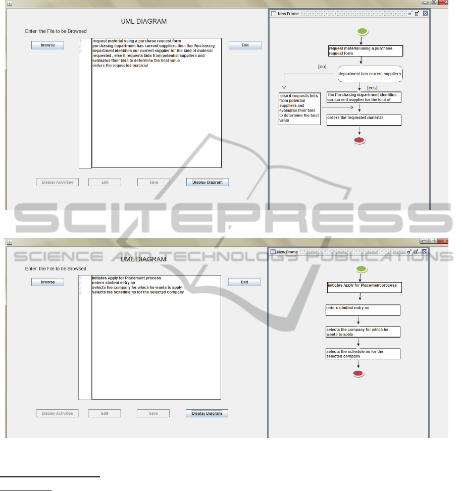
Figure 2: Activity Diagram - Scenario 1.
Figure 3: Activity Diagram - Scenario 2.
Decision Node Present:
Scenario 2: First we request material using a
purchase request form. If purchasing department
has current suppliers then the Purchasing
department identifies our current supplier for the
kind of material requested, else it requests bids from
potential suppliers and evaluates their bids to
determine the best value. Purchasing department
then orders the requested material.
Following similar approach as described for scenario
1, activity diagram for the scenario 2 is generated as
shown in figure 3 above.
4.2 Sequence Diagram
Sequence Diagrams are also generated using similar
approach as we have used for generating activity
diagrams. In order to generate sequence diagrams,
we first consider the actors or agents who are
responsible for carrying out an action; these are
identified by the ‘actor’ element in the frame. The
approach to identify action phrases is similar as that
for activity diagram generation. We present below
two possible different scenarios - scenario 3
considers the case when one user is responsible for
sequence of action initiations; scenario 4 depicts the
case of sequence of interactions between actors and
agents in a sequence:
AutomatedGenerationofActivityandSequenceDiagramsfromNaturalLanguageRequirements
75
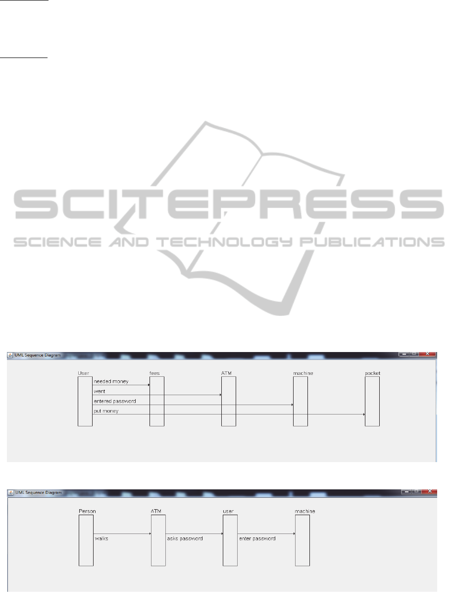
Scenario 3: Consider the following scenario of a
student registering for placement process: User
needed money for fees. User went to the ATM. User
entered password into the machine. User put the
money in her pocket.
Scenario 4: Consider the following ATM scenario:
The Person walks over to the ATM. ATM asks
password from the user. The user enter password
into the machine.
Sequence Diagrams for scenarios 3 and 4 are
presented in the figures 4 and 5 respectively below:
4.3 Limitations
One of the limitations of our work is that we are
assuming that scenarios for which we want to
generate UML behavioural diagrams are stated
without any redundant information. However,
redundancy and ambiguity are, often, present in
requirements documents and their presence can be a
possible threat to our approach. It is also possible
that sequence of actions is incorrect the stated
requirements scenario. In order to mitigate this
limitation, we have added an option to change the
sequence of actions displayed after automated
processing of requirements statements. The user can
modify the sequence or, the action statement itself
and confirm his submission so that his changes get
stored to the corresponding frame structure. The
diagrams are then generated in accordance to
modifications suggested by the user. However, this
manual intervention is optional and, is required only
if there are problems with the scenarios expressed in
the requirements documents.
5 DISCUSSION AND
CONCLUSION
The paper proposes an approach to automatically
generate activity and sequence diagrams from NL
requirements specifications. Our approach makes
use of intermediate structured representation of
requirements; and does not require any rewriting if
the statements, nor does it put any constraint on the
input format. These are some possible reasons that
existing approaches to automated generation of
UML diagrams have not proved very successful in
the industry. We have proposed a solution that stores
the textual representation of requirements in an
intermediate form that can accept changes (optional)
from the user too. However, the accuracy of our
approach is limited by the correctness of the results
provided by the Tagger and the Parser. Nevertheless,
the results using Stanford tagger and parser are quite
satisfactory. We believe that our approach will
substantially improve software requirements
analysis and consequently, will lead to improved
software development. We are further working on
trying complex scenarios as well as on automated
generation of other UML diagrams.
Figure 4: Sequence Diagram - Scenario 3.
Figure 5: Sequence Diagram - Scenario 4.
ENASE2014-9thInternationalConferenceonEvaluationofNovelSoftwareApproachestoSoftwareEngineering
76

REFERENCES
Sommerville, I., 2011, Software Engineering, Pearson.
India, 9
th
edition.
Svoboda, C.P., 1997, Structured Analysis, In: Thayer
R.H. and Dorfman M. (eds.), Software Requirements
Engineering, 2
nd
Edition, IEEE Computer Society
Press, Los Alamitos, CA, pp. 255-274.
Booch, G., 1994, Object-Oriented Analysis and Design
with Applications, Benjamin-Cummings Publishing
Co., Inc. Redwood City, CA, USA, 2
nd
edition.
Delugach, H.S., 1996, An approach to Conceptual
Feedback in Multiple Viewed Software Requirements
Modeling, In Viewpoints 1996: International
Workshop on Multiple Perspectives in Software
Development, San Francisco, CA, pp. 242-246.
Subramaniam, K., Liu, D., Far B. H. and Eberlein, A.,
2004, UCDA: Use Case Driven Development
Assistant Tool for Class Model Generation, In SEKE
’04: 16
th
International Conference on Software
Engineering and Knowledge Engineering, Canada, pp.
324-329.
Overmeyer, S. , Lavoie B. and Rambow, O., 2001,
Conceptual Modeling through Linguistic Analysis
using LIDA, In ICSE’01: 23rd International
Conference on Software Engineering, Canada, pp.
401-410.
Vinay, S. , Aithal S. and Desai, P., 2009, An Approach
towards Automation of Requirements Analysis, In
IMECS’09: International MultiConference of
Engineers and Computer Scientists, Hong-Kong.
Herchi, H. and Abdessalem, W.B., 2012, From user
requirements to UML class diagram, CoRR
abs/1211.0713.
More, P. and Phalnikar, R., 2012, Generating UML
Diagrams from Natural Language Specifications,
International Journal of Applied Information Systems,
vol. 1, no. 8, pp. 19-23.
Joshi, S.D. and Deshpande, D., 2012, Textual
Requirement Analysis for UML Diagram Extraction
by using NLP, International Journal of Computer
Applications, vol. 50, no. 8, pp. 42-46.
Ibrahim, M. and Ahmad, R., 2010, Class Diagram
Extraction from Textual Requirements Using Natural
Language Processing (NLP) Techniques, In 2
nd
International Conference on Computer Research and
Development, pp.200-204.
Ormandjieva, O. and Ilieva, M.G., 2006, Automatic
Comprehension of Textual User Requirements and
their Static and Dynamic Modeling, In SERP’06:
International Conference on Software Engineering
Research and Practice, Nevada, USA, pp. 266-273.
Deeptimahanti D.K. and Sanyal, R., 2008, Static UML
Model Generator from Analysis of Requirements
(SUGAR), In ASEA’08: International Conference on
Advanced Software Engineering and Its Applications,
China, pp. 77-84.
Deeptimahanti D.K. and Sanyal, R., 2011, Semi-automatic
Geneartion of UML Models from Natural Language
Requirements, In ISEC’11: 4
th
India Software
Engineering Conference, Kerala, India, pp. 165-174.
Li, L., 1999, A semi-automatic approach to translating use
cases to sequence diagrams, In Proceedings of
Technology of Object-Oriented Languages and
Systems, pp.184-193.
Yue, T., Briand, L.C. and Labiche, Y., 2010, An
Automated Approach to transform Use Cases into
Activity Diagrams, In ECMFA’10: Proceedings of 6
th
European Conference on Modeling Foundations and
Applications, Paris, France, pp. 337-353.
Erickson J. and Siau, K., 2007, Theoretical and Practical
complexity of modelling methods, ACM
Communications, vol. 50, no. 8, pp. 46-51.
M. Minsky, 1988, A Framework for Representing
Knowledge, In: Haugeland J. (ed.), Mind Design:
Philosophy, Pscychology, Artificial Intelligence, MIT
Press, Cambridge, MA, pp. 95-128.
Bowker, L., 2003, Lexical knowledge Patterns, Semantic
Relations, and Language Varieties: Exploring the
Possibilities for Refining Information Retrieval in an
International Context, In: Williamson N.J. and
Beghtol, C., (eds.), Knowledge Organization and
Classification in International Information Retrieval
co-published as Cataloging and Classification
Quarterly, 37(1), The Haworth Information Press,
Binghamton, NY, pp. 153-171.
Unified Modeling Language Specification, Version 1.5,
2003, OMG document, Available from:
http://www.omg.org/spec/UML/1.5/ [4 January 2014].
Marshman, E., Morgan T. and Meyer, I., 2002, French
patterns for expressing concept relations, Terminology,
vol. 8, no. 1, pp. 1-29.
Hunston S. and Francis, G., 2000, Pattern Grammar: A
Corpus-Driven Approach to the Lexical Grammar of
English, John Benjamins, Amsterdam.
Fikes, R. E. and Kehler, T., 1985, The role of frame-based
representation in knowledge representation and
reasoning, Communications of the ACM, vol. 28, no. 9,
pp. 904-920.
Luisa, M., Mariangela F. and Pierluigi, N.I., 2004, Market
Research on requirements analysis using linguistic
tools, Requirements Engineering, vol.9, no.1, pp. 40-
56.
Bhatia, J., Sharma, R., Biswas, K.K. and Ghaisas, S.,
2013, Using Grammatical Knowledge Patterns for
structuring requirements specifications, In RePa’13:
IEEE 3
rd
International Workshop on Requirements
Patterns, Rio De Janerio, Brazil, pp.31-34.
Toutanova, K., Klein, D., Manning, C. and Singer, Y.,
2003, Feature-Rich Part-of-Speech Tagging with a
Cyclic Dependency Network. In Proceedings of HLT-
NAACL 2003, pp. 252-259.
Marneffe, M. C. de, MacCartney, B. and Manning, C. D. ,
2006, Generating Typed Dependency Parses from
Phrase Structure Parses, In LREC 2006.
AutomatedGenerationofActivityandSequenceDiagramsfromNaturalLanguageRequirements
77
