
Creating a Reference Technology Platform
Performing Model-based Safety Analysis in a Heterogeneous Development
Environment
Omar Kacimi, Christian Ellen, Markus Oertel and Daniel Sojka
OFFIS, Escherweg 2, 26121 Oldenburg, Germany
Keywords:
Model-based Design, Safety Analysis, Tool Interoperability, Systems Engineering, Verification & Validation,
OSLC.
Abstract:
The interoperability of tools and methods is a topic being currently discussed across all engineering domains
of embedded systems. The increasing amount of requirements on interoperability demands a common
understanding of design artifacts which needs to be accessible beyond tool boundaries. Furthermore, to
support safety related development, a framework to integrate verification and validation activities has to be
established. This eases early design decisions and provides support for certification processes.
Different European projects tackled the subject and current ones like MBAT (Model-Based Analysis and
testing) are addressing it under the form of a so called Reference Technology Platform (RTP). Nevertheless,
besides theoretical discussions on interoperability standards and basic transfer technologies, few implementa-
tions of such a platform exist.
Within MBAT, we integrated an automated safety analysis into our existing RTP prototype. This setup was
developed for the purposes of an industrial case study calling upon a typical set of heterogeneous tools
and formats like MATLAB Simulink/Stateflow, IBM Rational DOORS and EAST-ADL. In this paper, we
present our RTP implementation and evaluate its effectiveness with respect to the safety aspects and the
interoperability challenges raised by the use case.
1 INTRODUCTION & RELATED
WORK
The development of safety critical systems require an
important effort of verification and validation activi-
ties. Especially in the automotive industry, a recent
change in methodology has been initiated by the in-
troduction of the ISO 26262 (ISO, 2011). The auto-
motive domain is known for using a broad spectrum
of different, often company specific tools in the de-
velopment lifecycle across the whole supply chain.
Suffering from the heterogeneous models and tools, a
global system view is needed to analyze safety prop-
erties. This system view contains mainly the require-
ments, the components and their implementations as
well as a comprehensive traceability between these el-
ements. In addition, the verification and validation ac-
tivities together with their results need to be available
for the safety case. Realizing the importance of the
subject, several European projects like CESAR (Ra-
jan and Wahl, 2013; H
¨
ardt et al., 2011; Oertel and
Josko, 2012), SPES 2020 (Damm et al., 2011) and
currently MBAT
1
are addressing the interoperabil-
ity of heterogeneous tools. Through these different
projects, the concept of a Reference Technology Plat-
form (RTP) was developed. Such a platform shall al-
low different tools to communicate and share their in-
formation.
Along with the idea of the RTP, many technolo-
gies emerge with the goal of enabling tool interoper-
ability. Open communities addressing tool interoper-
ability are rising such as OSLC (OSLC Community,
2013) which starts to distinguish itself as one of the
most preferred interoperability technologies. OSLC
builds on existing web and data linking standards such
as HTTP
2
and RDF/XML
3
as basis for interoperabil-
ity. Furthermore, global players in the software mar-
ket such as Dassault systems and IBM realized the
importance of an interoperability platform. Examples
are the Jazz technology developed by IBM which is
1
http://www.mbat-artemis.eu
2
http://www.w3.org/Protocols/rfc2616/rfc2616.html
3
http://www.w3.org/RDF/
645
Kacimi O., Ellen C., Oertel M. and Sojka D..
Creating a Reference Technology Platform - Performing Model-based Safety Analysis in a Heterogeneous Development Environment.
DOI: 10.5220/0004875306450652
In Proceedings of the 2nd International Conference on Model-Driven Engineering and Software Development (MBAT-2014), pages 645-652
ISBN: 978-989-758-007-9
Copyright
c
2014 SCITEPRESS (Science and Technology Publications, Lda.)

currently integrated e.g. in their requirements man-
agement tool DOORS(IBM, 2013) to enable OSLC
linking and web-based editing. Another example is
the ENOVIA platform from Dassault Systems.
In an automotive case study of the MBAT project,
it was required to provide means to analyze the safety
of a proposed system. The safety aspect aside, a set of
heterogeneous tools and models including MATLAB
SimulinkStateflow (Mathworks, 2013), IBM Ratio-
nal DOORS and EAST-ADL (ATESST Consortium,
2010) were used in the use case and traceability to in-
ternal components of the respective engineering mod-
els needed to be established. In this paper, we present
how the concept of an RTP is implemented to tackle
the tools heterogeneity challenge using OSLC as an
interoperability technology. Furthermore, we present
how an automated safety analysis is integrated in this
setup. Finally, we evaluate the effectiveness of our
implementation with respect to the safety and interop-
erability challenges (see requirement of the use case
in Section 2).
We start by describing the use case in Section 2
and derive various requirements. Subsequently, we
present the automated safety analysis to be integrated
in the RTP setup in Section 3 together with the ideas
behind the RTP. The RTP setup to achieve the de-
scribed goals and the evaluation results are presented
in Section 4. A conclusion of our approach and a fore-
cast to further developments is given in the final Sec-
tion 5.
2 PRESENTATION OF THE USE
CASE
The use case consists of an automotive turn indicator
system which controls the turning lights w.r.t different
kinds of car signals. These signals include: the lock-
ing and unlocking of the car, hazard lights and the
normal turn indicator signals as well. A part of the
Stateflow model consists of a main control unit which
is directly connected to a preprocessing unit for the in-
coming airbag signal (see the part outside the dashed
frame of Figure 1).
On the one hand, the first goal of the scenario is to
verify that there are no single points of failure in this
part of the model. The safety goal is defined as the
following: whenever a crash of the car has been de-
tected, the hazard light mode must be activated. This
requirement is formalized in the requirement specifi-
cation language (see Section 3) as follows:
whenever tr(crash sensor==1) occurs
tr(mode==hazard light) occurs during
[0steps, 1steps].
Main
control
logic
Signal
preprocessing 1
Signal
preprocessing 2
FM1
FM2
FM3
FM4
crash sensor
crash sensor
mode
FL
FR
RL
RR
or
hazard light
hazard light
Figure 1: High level overview of the turn indicator system
including two redundant preprocessing units and I/O faults.
The signal preprocessing subsystem is prone to two
types of malfunctions. First, the incoming signal to
the unit can be lost. Second, the processed output to
the main control unit can be lost. The two malfunc-
tions are defined respectively at implementation level
as the failure-modes: (FM1) and (FM2) (The concept of
failure-mode is further explained in Section 3.1).
On the other hand, like in the case of typical
development processes for safety relevant systems,
the safety requirements are attached to a component
model which is designed before the implementation.
Accordingly, in this use case an EAST-ADL model
describing the architecture as a set of components
with ports and connectors is used. The present State-
flow model is an implementation model of the com-
ponent representing the turn indicator system. Also,
for each component of the EAST-ADL model a faults
model is defined giving a high level view of the faults
that could occur in it. To store the requirement to be
verified, DOORS is used as a back-end. The second
goal of the use case is to provide means of establish-
ing full traceability between the artifacts of the anal-
ysis. The requirements need to be traced to the corre-
sponding EAST-ADL components that need to satisfy
them, each implementation model needs to be traced
to the component it implements. Furthermore, V&V
activities need to be traced to the artifacts they are
meant to validate.
Hence, the overall goal is providing a safety
methodology for identifying single points of failure
and a framework enabling integration of this method-
ology with the different engineering artifacts and
tools from the use case. We refine this goal into the
listed requirements.
Requirement 1
The proposed safety methodology needs to uncover
single points of failures.
It needs to be assured that there are no single point
MODELSWARD2014-InternationalConferenceonModel-DrivenEngineeringandSoftwareDevelopment
646

of failures leading to the violation of functional and
safety requirements. Hence, a methodology needs to
be proposed for this purpose providing confidence in
the results obtained. Also, evidence of how the occur-
rence of the faults lead to the violation of a require-
ment is needed to ease the process of correcting the
design.
Requirement 2
The distributed artifacts need to be accessible be-
tween the tools.
The different data resources used for the purposes
of the proposed safety methodology are distributed
among multiple data repositories. Therefore, a mech-
anism is needed to make the data resources accessible
to all the tools participating in the scenario.
Requirement 3
A common understanding of the artifacts is needed.
The use case comprises many engineering tools. Each
one has its own engineering models and its own un-
derstanding of artifacts. To ease traceability and the
integration of new tools with the ones already present,
a common semantic understanding of engineering ar-
tifacts needs to be established between the tools of the
use case. Furthermore, this understanding needs to
support the integration of the tools that are proposed
by the safety methodology.
Requirement 4
All data artifacts need to be traceable.
One of the challenges in the development of a safety
critical system is the need for traceability of elements
throughout the development process. Within our so-
lution, we need to establish traceability between all
the artifacts used in the defined safety methodology.
Requirement 5
V&V activities must be globally available and
reusable.
Once a V&V activity has been specified it must be
possible to (re-)execute it. Especially after changes
on related artifacts (e.g. detected by a change-impact
analysis (Oertel and Rettberg, 2013)). It should be
possible to ensure that new changes do not violate the
requirements of the system.
3 PRESENTATION OF THE MBSA
AND THE RTP
Analyzing the needs of the use case raised a set of re-
quirements targeting the elimination of single points
of failures and the interoperability of the used tools in
the scenario.
We propose our Model-based Safety Analysis
(MBSA) (Peikenkamp et al., 2006) to address Re-
quirement 1, a work that has been initiated in the
ESACS project (Bozzano et al., 2003) and has been
continuously developed throughout different Euro-
pean projects.
3.1 MBSA
The MBSA is a comprehensive analysis which for-
mally verifies that an implementation model, includ-
ing safety mechanisms, does not violate a safety goal.
Many kinds of implementation models can be con-
sidered a target of such an analysis. In this use case
we focus on Stateflow models. Stateflow models are
discrete state-transition diagrams and can be used in
the design process to verify the control logic of the
system under development before its implementation.
Accordingly, the designer can uncover design flaws
before the implementation is started and an iterative
improvement of the design w.r.t. robustness against
faults is done every time the model is analyzed.
For the specification of safety goals our approach
supports contract-based design (Meyer, 1992) in ad-
dition to “normal” requirements. A contract does not
only consist of the required statement called promise,
but also of an assumption which specifies a condition
under which the requirement shall hold. For require-
ments formalization, RSL (Mitschke et al., 2010) (Re-
quirements Specification Language) is used: this lan-
guage enables the specification of unambiguous re-
quirements using predefined patterns.
Finally, the dysfunctional behavior investigated by
the analysis is specified as a set of failure-modes. A
failure-mode is an abnormal behavior occurring to a
variable in the Stateflow model. It alters normal op-
eration flow. In the use case the following three types
of failure-modes were used:
• Stuck-at failure-mode: their occurrence describe
the case that an internal variable of the system is
stuck to an erroneous value. Write operations to
the variable are disabled and read operations can
only access the faulty value e.g. the variable tem-
perature is stuck at the value 0.
• Random failure-mode: if a failure-mode of this
type occurs to an internal variable its value can
change randomly during system runs.
• User defined failure-mode: this is a means to
model specific complex error behavior which is
not covered by the types already defined, it is ex-
clusively applied to inputs of the system. For
these failure-modes at the inputs we need to de-
scribe the nominal behavior. All deviations from
CreatingaReferenceTechnologyPlatform-PerformingModel-basedSafetyAnalysisinaHeterogeneousDevelopment
Environment
647

the provided value are considered an occurrence
of the failure-mode e.g. the nominal behavior for
the variable pressure is having the value: 10, oth-
erwise the pressure is considered to be abnormal
(a malfunction has occurred on the related input).
Once all the inputs of the analysis are available,
the Stateflow model is converted to a format under-
standable by the VIS model checker
4
and is ex-
tended by the dysfunctional behavior described by the
failure-modes. Furthermore, the safety goal is trans-
lated to an automaton which acts as an observer and
is added to the same resulting model.
At execution time, the analysis calls VIS to ex-
plore symbolically the full state space of the system
obtaining all the paths where one or many failure-
modes were active and the violation of the safety
goal occurred. A further step of the analysis extracts
the minimal paths from the computed ones i.e. the
ones where the minimum number of failure-modes
occurs. Minimal cut-sets are identified based on the
minimal paths. The cut-sets are unique combina-
tions of malfunctions occurrences that can cause sys-
tem failure. A cut-set is said to be minimal if, when
any basic event is removed from the set, the remain-
ing events collectively are no longer a cut-set (Kece-
cioglu, 1991). Finally, for each generated minimal
cut-set the analysis produces an execution trace. The
execution trace provides concrete evidence of how the
occurrence of the failure-modes leads to the violation
of the safety goal. Hence, the resulting cut-sets are
evaluated by a safety engineer to estimate their con-
formity with the safety requirements. In case of non
conformity, the execution traces assist the safety en-
gineer in the enhancement of the design.
The MBSA is introduced as a solution for iden-
tifying single points of failure. It is still necessary
to develop a solution to cope with the heterogeneous
tool environment in which our MBSA needs to oper-
ate. Accordingly, we propose an RTP implementation
of the tools from the use case in which the MBSA will
be integrated. We present first the main ideas behind
the RTP and the direction toward which it is going
within MBAT.
3.2 RTP
In Section 2 we identified the need for multiple tools
to interact. Between many problems of tools interop-
erability, all the tools need to have the same under-
standing of engineering artifacts. Also, the tools need
to agree on a technique to exchange data resources
that can be used by all of them. To tackle similar
4
http://vlsi.colorado.edu/
˜
vis/
issues, different European projects address the prob-
lem under the form of a so called Reference Tech-
nology Platform. Such a platform shall provide a
common understanding of the engineering artifacts
of the tools: a meta-model providing a common se-
mantic understanding of the tools engineering mod-
els (internal representations of data resources) while
abstracting from them. Such a meta-model will con-
sist of concepts, relationships and properties. Also,
an agreement is needed on the syntactical represen-
tation and the transmission technology. Once these
elements are set, each of the engineering tools inte-
grated in the RTP will need to create an adapter pro-
viding its data in this agreed format. In RTP terms,
the semantic, syntactical and technical agreement is
referred to as an IOS (Interoperability Specification).
During the different projects in which the idea of
an RTP is addressed, many attempts for a suitable
IOS were made and lately OSLC (OSLC Commu-
nity, 2013) has risen as a promising approach and
is currently being used in MBAT. OSLC is an open
community project aiming to ease tool integration. It
builds upon established internet and linked-data stan-
dards like HTTP
5
, RDF/XML
6
, RESTful services
7
,
as well as open and extendible minimalistic data spec-
ifications. RDF/XML provides a common syntax
to describe data resources as subject-predicate-object
triplets. OSLC provides a basic semantic specifica-
tion for data resources, their types and the relation-
ships between them. These specifications are modu-
lar with regard to domains like Requirements Man-
agement or Architecture Management that reflect dif-
ferent engineering disciplines. For typical workflows,
these resource types need to be extended using con-
cepts of a domain meta-model. Finally, the difference
between an RTP and its instances needs to be noticed.
An RTP consists of all tools and processes able to
interact using a defined IOS. The RTP instance is a
company specific tailoring w.r.t. a selection of these
tools.
4 REALIZATION OF THE
PROPOSED SOLUTION
The RTP instance we present was developed using
concepts created in the MBAT project. Namely, the
MBAT meta-model and the MBAT IOS. The design
process to apply these technologies to the scenario at
hand is guided by the so-called IOS recipe which de-
5
http://www.w3.org/Protocols/rfc2616/rfc2616.html
6
http://www.w3.org/RDF/
7
http://www.w3.org/2001/sw/wiki/REST
MODELSWARD2014-InternationalConferenceonModel-DrivenEngineeringandSoftwareDevelopment
648

MBSA
VV Case
Component Model
F1 F2
F3 F4
C4
C3
C1
C2
Requirements
Contract 1
Contract 2
Contract 3
Implementation
FM2FM1
FM4
FM3
<implement>
<Satisfy>
StateFlow
<implement>
<Evaluate>
<Evaluate>
<Evaluate>
Component
Figure 2: Overview of the data concepts manipulated by the
analysis.
scribes a guideline for establishing the IOS of hetero-
geneous engineering tools using OSLC technologies
(Baumgart and Ellen, 2014).
4.1 Application Of The Recipe
The main prerequisite of the recipe is the definition
of a scenario plan which defines the overall workflow
and allocates the individual steps to different engi-
neering tools. In this case for instance, we are using
EAST-ADL to realize the component modeling part
and Stateflow for the implementation model. Based
on these decisions, the first step of the recipe can
be applied. It is the identification of the individual
engineering model elements which need to be com-
municated between the tools. Each tool has its own
internal engineering model and in most cases it is
not necessary to share all the detailed information
of the engineering models between tools. A filter-
ing to a minimal set of elements in this step can re-
duce the overall effort to achieve interoperability for
the scenario. As an example, DOORS needs to ex-
pose the requirements and the contracts stored in its
internal table structure. The MBSA needs the imple-
mentation model it will analyze, the corresponding
failure-modes and the safety goal as a requirement
from DOORS. The outputs it needs to provide are
the generated minimal cut-sets, the execution traces
and the verdict of the analysis (Success or Failure).
For EAST-ADL a similar filtering can be applied.
Only the architectural part of the component hierar-
chy and the error behavior (containing the fault defini-
tions) are needed. Such a filtering is not always possi-
ble. In case of the Simulink/Stateflow implementation
model all detailed information is required to perform
the analysis. Any removed or abstracted information
could potentially result in a incorrect representation of
the model. Therefore, the first possible option is to in-
tegrate all Stateflow elements in the meta-model used
for the IOS and make them available over OSLC. A
second option –the one implemented in our solution–
is to fully abstract the implementation model by a
black box. The benefit of this solution is that it is still
possible to trace the components from EAST-ADL
to their corresponding implementations by using the
Stateflow model files directly as representatives of an
implementation. The second step within the interop-
erability recipe is to allocate the identified engineer-
ing model elements to artifacts of a conceptual com-
mon meta-model (e.g. the MBAT meta-model). This
meta-model represents an implementation indepen-
dent consensus on elements and concepts of the tools
which can be used for alignment among the different
parties involved in the development of the RTP. For
example, the meta-model concept Implement link
represents the traceability relationship between the
two concepts Component and implementation. Re-
spectively EAST-ADL components are mapped to the
meta-model concept: Component and stateflow model
files are mapped to the concept: implementation.
Furthermore, the Failure-Mode concept describes
the failure-modes needed for the MBSA and the
Fault concept describes the faults from the error
model in EAST-ADL. To describe a V&V activity
the general concept of a VV Case is used. The el-
ements necessary for starting the MBSA are refer-
enced in a VV Case. For an excerpt of these ele-
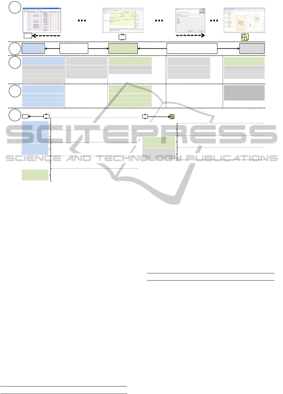
ments see Figure 2. The third step consists of al-
locating the concepts of the identified meta-model to
the resource types defined by OSLC. For example
the Component concept is allocated to the general re-
source type Resource of the OSLC oslc am domain.
Another example is the VV Case concept allocated to
the resource type Test Case of the OSLC oslc qm
domain. The fourth step is the implementation of
the IOS. the IOS concepts are the refinement of the
OSLC resource types to which the meta-model con-
cepts are mapped. For instance, the IOS resource type
Component is the refinement of the OSLC resource
type Resource from the oslc am domain by the prop-
erties of the Component meta-model concept. Finally,
the fifth step of the recipe consists of implement-
ing the IOS resource types. Different IOS resource
types implementations together with OSLC compliant
communications are possible. Our implementation is
based on the Eclipse Modeling Framework (EMF),
the servlet-engine and HTTP-server Jetty from the
Eclipse Foundation, as well as the RDF-library and
the serializer Jena from the Apache Software Foun-
dation. The final outcome of the recipe is an OSLC
based IOS. The meta-model concepts and IOS re-
CreatingaReferenceTechnologyPlatform-PerformingModel-basedSafetyAnalysisinaHeterogeneousDevelopment
Environment
649
EAST-ADL
- Component Model
- Fault Definition
DOORS-Database
MATLAB/ Stateflow
- Implementation Model
- Failure Mode Definition
VV Management
- VV Case
- VV Log
PatternEditor
Traceability
- Satisfy Link
- Implementation Link
RTP Services
RTP Clients
VV Editor
OSLC Transfer Layer
Link Tool
- Contract
- RSL-Requirement
- VV Log
- VV Cases
- TraceLinks
- Contract
- RSL-Requirement
MBSA
- VV Log
- VV Case
RTP Analysis
services
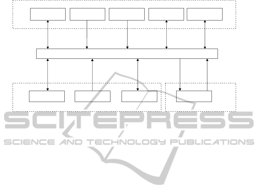
Figure 3: Overview of the implemented RTP.
source types specified in the MBAT project defined
the necessary refinement for our RTP instance. The
presented steps of the recipe are illustrated in Figure
4. Based on the defined IOS, our RTP instance could
be implemented.
4.2 Implementation of the RTP
Our RTP instance is composed of three types of el-
ements. First, RTP services manage the data re-
sources. Besides providing a set of possible oper-
ations which can be performed on the data it man-
ages, each service performs the role of a tool/data
adapter. The services provide the data elements
they manage as IOS resources described in RDF. For
instance, the DOORS-Database Service communi-
cates with DOORS used as back-end, retrieves the re-
quirement and provides it as an IOS contract when
it’s needed. This particular service offers require-
ments CRU (creation, read and update) operations
while the Stateflow models service only offers
read operations: MATLAB models are only used as
targets for traceability links.
Second, we created RTP clients to communi-
cate with the proposed services. For example, the
PatternEditor tool which can perform the opera-
tions allowed by the DOORS-Database Service so
that the user can edit and formalize requirements. In
order to update a requirement, the PatternEditor
sends a browse request to the service which answers
with a list of all available requirements. After the user
selects a specific one, the PatternEditor queries the
service which returns a requirement serialized as an
RDF String using HTTP. The PatternEditor dese-
rializes the string and the requirement object is ex-
tracted from the resource. The PatternEditor se-
rializes the requirement to RDF and sends it back to
the DOORS-Database service once the user opera-
tions are complete. The DOORS-Database service
receives the RDF String, extracts the data from
the requirement object and updates the underlying
database. To create traceability links the RTP Link
Tool was created. In the same fashion as the
PatternEditor, the tool queries services for one of
their elements to allow the user to link them. Once
the artifacts to be linked are selected, the tool sends
a creation request to the traceability repository. Ac-
cordingly, a trace link referencing the traced elements
is created and stored. In step 5 of the recipe (Figure
4) a link and a contract encoded in RDF are shown.
The third type of RTP elements we created is:
Analysis Services. These perform operations on
data resources and output results either as newly
created data resources or as modifications to their
input data resources. To start the MBSA for in-
stance, the user creates first a VV Case and links it
to the corresponding implementation link, satisfy link
and failure-modes (see Figure 2). The VV Editor
calls finally the MBSA analysis Service with the
VV Case as a parameter. The service produces then
several VV Outcomes as results: the generated cut-
sets, the corresponding execution traces and the re-
sulting verdict of the analysis (SUCCESS or FAIL).
The created VV Outcomes are referenced in a corre-
sponding VV Log which keeps track of the execution
of the analysis and the created VV Log is referenced
on its turn in the VV Case. The VV Cases are man-
aged by the VV Management Service, this service
MODELSWARD2014-InternationalConferenceonModel-DrivenEngineeringandSoftwareDevelopment
650
<rdf:RDF
xmlns:rdf="http://www.w3.org/1999/02/22-rdf-syntax-ns#"
xmlns:rdfs=“http://www.w3.org/TR/rdf-schema/#”
xmlns:dcterms=“http://purl.org/dc/terms/”
xmlns:ios_am="http://ios.artemis.eu/ns/am#"
xmlns:ios_tm="http://ios.artemis.eu/ns/tm#"
xmlns:mylinktool="http://linkage.com/mylinktool/">
<rdf:Description rdf:about="http://127.0.0.1:8005/00002722/links/1">
<ios_tm:implementedBy rdf:nodeID="A0"/>
<ios_tm:implements rdf:nodeID="A1"/>
<dcterms:title rdf:datatype=" http://www.w3.org/1999/02/22-rdf-syntax-ns#XMLLiteral ">C0_implements_B0</dcterms:title>
<rdfs:label rdf:datatype="http://www.w3.org/2001/XMLSchema#string">satisfy</rdfs:label>
<rdf:type>http://ios.artemis.eu/ns/tm#ImplementationLink http://linkage.com/mylinktool/Link</rdf:type>
</rdf:Description>
<rdf:Description rdf:nodeID="A0">
<rdf:_1 rdf:resource=“http://modelserver.local/models/testcomponents.model#12693 "/>
<rdf:type rdf:resource="http://www.w3.org/1999/02/22-rdf-syntax-ns#Bag"/>
</rdf:Description>
<rdf:Description rdf:about="http://modelserver.local/models/testcomponents.model#12693">
<rdf:type>http://ios.artemis.eu/ns/am#Component</rdf:type>
</rdf:Description>
<rdf:Description rdf:nodeID="A1">
<rdf:_1 rdf:resource="http://simulinkserver.local/models/testmodel.slx/19238# "/>
<rdf:type rdf:resource="http://www.w3.org/1999/02/22-rdf-syntax-ns#Bag"/>
</rdf:Description>
<rdf:Description rdf:about=" http://simulinkserver.local/models/testmodel.slx/19238# ">
<rdf:type>http://ios.artemis.eu/ns/am#Behavior</rdf:type>
</rdf:Description>
</rdf:RDF>
<rdf:RDF xmlns:rdf="http://www.w3.org/1999/02/22-rdf-syntax-ns#” xmlns:rdfs=“ttp://www.w3.org/TR/rdf-schema/#” xmlns:dcterms=“http://purl.org/dc/terms/”
xmlns:oslc_rm="http://open-services.net/ns/rm#" xmlns:ios_rm="http://ios.artemis.eu/ns/rm#"
xmlns:myrequirements=“http://mycompany.com/local/ns/requirements/”
xmlns:ios_am="http://ios.artemis.eu/ns/am#" xmlns:ios_tm="http://ios.artemis.eu/ns/tm#">
<rdf:Description rdf:about="http://127.0.0.1:8005/00002722/278#//@attribute1">
<dcterms:title rdf:datatype=“http://www.w3.org/1999/02/22-rdf-syntax-ns#XMLLiteral">
Assumption</dcterms:title>
<dcterms:description rdf:datatype="http://www.w3.org/1999/02/22-rdf-syntax-ns#XMLLiteral ">
always speed < 30 km/h</dcterms:description>
<rdf:type>http://rtp.artemis.eu/ns/rm#Assertion http://mycompany.com/local/ns/requirements/Attribute</rdf:type>
</rdf:Description>
<rdf:Description rdf:about="http://127.0.0.1:8005/00002722/278#//@description">
<dcterms:title rdf:datatype=“http://www.w3.org/1999/02/22-rdf-syntax-ns#XMLLiteral">
Promise</dcterms:title>
<dcterms:description rdf:datatype=" http://www.w3.org/1999/02/22-rdf-syntax-ns#XMLLiteral ">
whenever crash_detected occurs deploy_airbag does not occur</dcterms:description>
<rdf:type>http://ios.artemis.eu/ns/rm#Assertion http://mycompany.com/local/ns/requirements/Description</rdf:type>
</rdf:Description>
<rdf:Description rdf:about="http://127.0.0.1:8005/00002722/278">
<ios_rm:promise rdf:resource="http://127.0.0.1:8005/00002722/278#//@description"/>
<ios_rm:assumption rdf:resource="http://127.0.0.1:8005/00002722/278#//@attribute1"/>
<dcterms:title rdf:datatype=" http://www.w3.org/1999/02/22-rdf-syntax-ns#XMLLiteral ">R0</dcterms:title>
<rdf:type> http://ios.artemis.eu/ns/rm#Contract
http://open-services.net/ns/rm#Requirement
http://mycompany.com/local/ns/requirements/MyCompanySpecialRequirement</rdf:type>
</rdf:Description>
<rdf:Description rdf:about="http://127.0.0.1:8005/00002722/links/1">
<oslc2_tm:satisfiedBy rdf:nodeID="A0"/>
<oslc2_tm:satisfies rdf:nodeID="A1"/>
<dcterms:title rdf:datatype=" http://www.w3.org/1999/02/22-rdf-syntax-ns#XMLLiteral ">C0_satisfy_R0</dcterms:title>
<rdfs:label rdf:datatype="http://www.w3.org/2001/XMLSchema#string">satisfy</rdfs:label>
<rdf:type>http://ios.artemis.eu/ns/tm#SatisfyLink http://linkage.com/mylinktool/Link</rdf:type>
</rdf:Description>
<rdf:Description rdf:nodeID="A0">
<rdf:_1 rdf:resource=“http://modelserver.local/models/testcomponents.model#12693 "/>
<rdf:type rdf:resource="http://www.w3.org/1999/02/22-rdf-syntax-ns#Bag"/>
</rdf:Description>
<rdf:Description rdf:about="http://modelserver.local/models/testcomponents.model#12693">
<rdf:type>http://ios.artemis.eu/ns/am#Component</rdf:type>
</rdf:Description></rdf:RDF>
DOORS
Papyrus
Link Tool Simulink
Contract Satisfy Link Component Implementation Link Behavior
OSLC
Resource Type:
oslc_rm:Requirement
dcterms:title
dcterms:description
dcterms:subject
…
OSLC
Resource Type:
oslc_am:Resource
dcterms:title
…
OSLC
Resource Type:
oslc_am:Resource
dcterms:title
dcterms:description
…
OSLC
Resource Type:
oslc:Resource
dcterms:title
rdfs:label
…
IOS
Contract /
Requirement
IOS
Assertion
(promise)
IOS
Assertion
(assumption)
Contract
R
C
<< satisfy >>
IOS
Component
(satisfiedBy)
IOS
Satisfy Link
satisfies
satisfiedBy implementedBy implements
IOS
Behavior
(implements)
IOS
Component
(implementedBy)
IOS
Implementation Link
C
<< implementation >>
Implementation Link
R
<< satisfy >>
C
<< implementation >>
1
2
3
4
5
Refined
IOS Resource Type:
ios_rm:Contract
ios_rm:assumption
ios_rm:promise
ios_rm:specificationType
Refined
IOS Resource
Type:
ios_tm:SatisfyLink
ios_tm:satisfiedBy
ios_tm:satisfies
OSLC
Resource Type:
oslc:Resource
dcterms:title
rdfs:label
…
Refined
IOS Resource Type:
ios_am:Component
ios_am:interconnection
ios_am:part
ios_am:port
Refined
IOS Resource Type:
ios_tm:ImplementationLink
ios_tm:implementedBy
ios_tm:implements
Refined
IOS Resource
Type:
ios_am:Behavior
OSLC Base Type:
oslc_am:Resource
RDF
RDF
Figure 4: Steps of the recipe.
allows CRU operations used by the VV Editor tool
to allow the user to manage the V&V activities and
start them. Besides its use in this RTP instance, the VV
Editor serves the purpose of having a central point
for managing and starting different V&V activities,
this way the current implementation can be extended
easily for further analysis services such as change im-
pact analysis (Oertel and Rettberg, 2013). Our RTP
implementation is sketched in Figure 3.
4.3 Evaluation
To run the MBSA on the original design model, many
VV Cases were defined. One of these VV Cases were
created to investigate the effects of the two failure-
modes: FM1 and FM2 (see Figure 1 ). FM1 is a stuck-
at failure-mode, in the event it is enabled the variable
corresponding to the crash sensor in the signal prepro-
cessing unit will be stuck at the value FALSE. FM2 is
a random failure-mode: if enabled, the variable corre-
sponding to the hazard light activation in the prepro-
cessing unit can change its value randomly. Running
the VV Case with the requirement from Section 2 re-
sults in the following minimal cut-sets:
{FM1},{FM2}
The execution trace generated by the analysis
helped identifying the need for implementing a redun-
dancy of the preprocessing unit. Also, an OR gate that
passes the signal to the main control unit in case one
of the preprocessing units detected a crash is added.
The second preprocessing unit is prone to the same
type of malfunctions than the first one: FM3 and FM4
as shown in Figure 1. We define a new VV Case with
the four possible failure-modes. Running it results in
the following :
{FM1,FM3},{FM1,FM4},{FM2,FM3},{FM2,FM4}
Since all cut sets are of size two, we were able
to ensure that no single point of failure leads to a vi-
olation of the requirement. Furthermore, the use of
symbolic model checking assured the exploration of
the system’s full state space. We are sure of obtaining
all the cut-sets that could lead to the violation of the
safety goal. The requirements of the use c.
5 CONCLUSIONS
We demonstrated in this paper the integration of a
complex safety analysis in a heterogeneous tool en-
vironment. The presented automotive use case estab-
lished an interaction between IBM Rational DOORS,
CreatingaReferenceTechnologyPlatform-PerformingModel-basedSafetyAnalysisinaHeterogeneousDevelopment
Environment
651

MATLAB Simulink/Stateflow, EAST-ADL and the
Safety Analysis tool.
We implemented a Reference technology Plat-
form instance based on OSLC and extended the ex-
isting concepts with additional ones for the handling
of validation and verification activities as well as re-
quirements formalization, design and implementation
models support and trace-link management.
The resulting “V&V enabled” RTP instance al-
lows the creation of V&V activities for the analysis
of the satisfaction of requirements. We demonstrated
these capabilities by performing a single-point-of-
failure analysis integrating the data from all the above
mentioned tools.
The presented setup can be used as an interop-
erable solution to combine analysis and testing: the
counterexamples derived from the cut-sets can be
used to compute test vectors for test cases. These test
cases could be generated to check the violation of a
safety requirement.
Some extensions to the presented setup are
planned. In order to automatically re-run analyzes
in case of changes on the related artifacts, we plan
to integrate change impact analysis within our V&V
RTP instance. For example, the MBSA can be re-
ran each time a failure mode or a fault is added or
either a requirement or one of the models change
(changes detected by a change impact analysis). To
detect such changes, new services need to be imple-
mented. OSLC features like automation services are
planned to be used to implement these extensions. In
addition, the set of Simulink/Stateflow language fea-
tures supported by our MBSA is being extended and
it is planned to publish it in the near future.
ACKNOWLEDGEMENTS
The research leading to these results has received
funding from the ARTEMIS Joint Undertaking within
the European project MBAT under grant agreement
n°269335 and from the German Federal Ministry of
Education and Research (BMBF) under grant number
01IS11003L. The responsibility for the content of this
publication lies with the authors.
REFERENCES
ATESST Consortium (2010). EAST-ADL Do-
main Model Specification. ATESST
Deliverable D4.1.1, Version 2.1 RC3,
http://www.atesst.org/home/liblocal/docs/ATESST2
D4.1.1 EAST-ADL2-Specification 2010-06-02.pdf.
Baumgart, A. and Ellen, C. (to be published 2014). A recipe
for tool interoperability. In Proceedings of the MOD-
ELSWARD 2014 Conference.
Bozzano, M., Villafiorita, A.,
˚
Akerlund, O., Bieber, P.,
Bougnol, C., B
¨
ode, E., Bretschneider, M., Cavallo, A.,
Castel, C., Cifaldi, M., et al. (2003). Esacs: an inte-
grated methodology for design and safety analysis of
complex systems. In Proc. ESREL, pages 237–245.
Damm, W., Hungar, H., Henkler, S., Stierand, I., Josko, B.,
Reinkemeier, P., Baumgart, A., B
¨
uker, M., Gezgin, T.,
Ehmen, G., and Weber, R. (2011). SPES2020 Archi-
tecture Modeling. Technical report, OFFIS e.V.
H
¨
ardt, C., Viglietti, I., and Ersch, R. (2011). Interoperability
Specification. CESAR Deliverable D SP1 R1.5 M2,
CESAR Project.
IBM (2013). Rational doors next generation.
https://jazz.net/products/rational-doors/.
ISO (2011). Road Vehicles - Functional Safety. Interna-
tional Standard Organization. ISO 26262.
Kececioglu, D. (1991). Reliability engineering handbook:
Volume i. PTR Prentice Hall, Englewood Cliffs, New
Jersey.
Mathworks (2013). Matlab simulink/stateflow.
http://www.mathworks.de/products/simulink/.
Meyer, B. (1992). Applying ”design by contract”. Com-
puter, 25(10):40–51.
Mitschke, A., Loughran, N., Josko, B., Oertel, M., Rehkop,
P., H
¨
ausler, S., and Benveniste, A. (2010). RE Lan-
guage Definitions to formalize multi-criteria require-
ments V2.
Oertel, M. and Josko, B. (2012). Interoperable requirements
engineering: Tool independent specification, valida-
tion and impact analysis. In ARTEMIS Technology
Conference 2012.
Oertel, M. and Rettberg, A. (2013). Reducing re-
verification effort by requirement-based change man-
agement. In Embedded Systems: Design, Analysis and
Verification, pages 104–115. Springer Berlin Heidel-
berg.
OSLC Community (2013). Open Services for Lifecycle
Collaboration. http://open-services.net/.
Peikenkamp, T., Cavallo, A., Valacca, L., B
¨
ode, E., Pret-
zer, M., and Hahn, E. M. (2006). Towards a uni-
fied model-based safety assessment. In Proceedings
of SAFECOMP, pages 275–288.
Rajan, A. and Wahl, T. (2013). CESAR: Cost-efficient Meth-
ods and Processes for Safety-relevant Embedded Sys-
tems. Number 978-3709113868. Springer.
MODELSWARD2014-InternationalConferenceonModel-DrivenEngineeringandSoftwareDevelopment
652
