
Semantic Interoperability for Smart Grid
CIM Adoption Process
Alfredo Espinosa-Reza, Tito Manuel Calleros-Torres, Marxa Lenina Torres-Espíndola,
Nestor Adrian Aleman-Cruz and Raul Garcia-Mendoza
Instituto de Investigaciones Electricas, Reforma 113, Col. Palmira, Cuernavaca, Morelos, Mexico
Keywords: Smart Grid, Common Information Model (CIM), Semantic Interoperability, Distribution Management.
Abstract: This paper describes the experience obtained in the adoption process of the Common Information Model
(CIM) as part of definition of a strategy for semantic interoperability for legacy information systems of
Comision Federal de Electricidad (CFE by its acronym in Spanish). The strategy and the process described
are supported by standards IEC 61968 and IEC 61970, as well as best practice in software development in
the international context. Overall, the architecture for interoperability and the adoption process, will
establish a solid infrastructure designed to meet Smart Grid requirements for management systems for the
Electric Power System (EPS) in Mexico. Some results are discussed.
1 INTRODUCTION
The electric market deregulation in USA, Europe
and several countries in the world, as well as
emergent technologies required to establish the
vision of Smart Grid have increased the need of the
electric utilities to exchange information in a daily
way, thus, overall they must ensure the reliability of
the operation of interconnected electric systems.
Likewise, all electric utilities uses internally a
great quantity of formats and technologies for
systems and functions for manage the electric power
system, considering data storage in several databases
(hierarchical, relational, object oriented, geospatial)
and files in custom formats, as well as operating
systems of any kind and supplier, even though being
incompatible among them.
In this way, it has become exponential the
problem of develop and maintain updated a great
quantity of data interfaces, many processes for
exporting and importing information, as well as
several requirements to transform the exchanged
data, all of this coupled to a typical problematic: the
information and function duplicity, that happens
when two or more systems contain the same data or
perform the same function; the data inconsistency is
evident when two systems have different values for
the same data; and the incompatibility that occurs
when the information of two or more systems, it
cannot be combined for technological causes,
political, syntactical or semantic (Parra et al., 2012).
Smart Grid will be a great set of systems of
interconnected systems (electric and computerized),
thus being every time more evident the necessities of
interoperability of the information systems in charge
of monitoring, control and manage, overall, due to
the advanced functions that are being defined,
establish as a premise the capability of information
exchange in agile and expeditious manner.
2 SEMANTIC
INTEROPERABILITY
Interoperability refers to the capability of two or
more networks, systems, devices, applications, or
components to exchange and readily use
information—securely, effectively, and with little or
no inconvenience to the user (NIST, 2012).
According to the reference framework defined by
the GridWise in (GWAC, 2008), the informative
interoperability covers the content, the semantics
and the data format or instruction flows (as are the
accepted meaning of human beings and
programming languages). It focuses into which
information is exchanged and its meaning. It
establishes the understanding of the contained
concepts in the data structures of exchanged
90
Espinosa-Reza A., Calleros-Torres T., Torres-Espíndola M., Aleman-Cruz N. and Garcia-Mendoza R..
Semantic Interoperability for Smart Grid - CIM Adoption Process.
DOI: 10.5220/0004870800900095
In Proceedings of the 3rd International Conference on Smart Grids and Green IT Systems (SMARTGREENS-2014), pages 90-95
ISBN: 978-989-758-025-3
Copyright
c
2014 SCITEPRESS (Science and Technology Publications, Lda.)
messages, and integrates knowledge of the business
related to the semantics or meaning in the work flow
of a process. For the first time, the exchanged data
are associated to the electric infrastructure of the
enterprise and rules are established that ensure that
the exchanged data meet the semantic definitions
established in an Information Model, being general
and independent of technological platforms,
systems, brands or suppliers.
The Common Information Model (CIM) is a
generic Model, open and standard that can be
adopted by any enterprise. CIM is defined in a group
of standards of the IEC, being the most important:
IEC 61970-301 which defines the Model CIM Base
for Transmission Power Systems for use in Energy
Management Systems (EMS), IEC 61968-11 which
defines the CIM extensions for Distribution Power
Systems and IEC 62325-301 that establishes the
extensions for the Electric Market or CME (CIM for
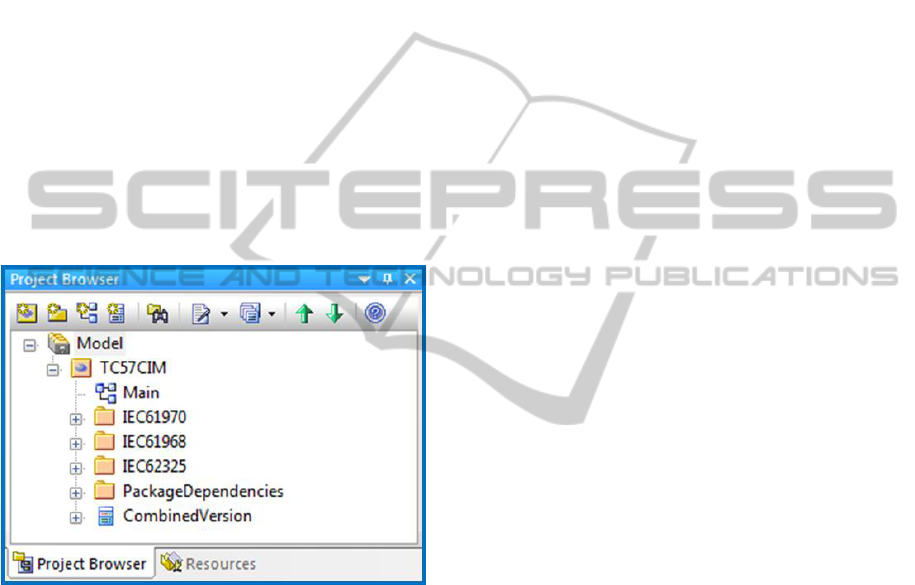
Market Extensions). Figure 1 shows these three
standards as UML packages in Enterprise Architect.
Figure 1: CIM packages in UML.
CIM have three primary uses: to facilitate the
exchange of power system network data between
organizations, to allow the exchange of data between
applications within an organization, and to exchange
market data between organizations. (EPRI, 2011).
2.1 CIM History
The CIM is a set of open standards for representing
power system components originally developed by
the Electric Power Research Institute (EPRI) in
North America and now a series of standards under
the International Electrotechnical Commission
(IEC). (EPRI, 2011).
CIM was started in 1992 as part of the Control
Centre API ( CCAPI) of EPRI; from 1993 to 1996 it
was developed with main target of allowing the use
of compatible applications in order to protect the
investment of the enterprises (E-R diagrams in MS-
Visio were used and MS-Access as Database); in
1996 the CIM was transferred to the IEC, to the 57
Technical Committee (TC57) and 13 and 14
working groups (WG13 and WG14), the
Transmission and Distribution areas were covered
(UML was adopted as modeling language and it was
kept in Rational Rose); in 2000 the first
interoperability test was performed; in 2003 the CIM
for Market Extensions (CME) development was
initiated, followed by the models for Planning and
Dynamics, currently the model for Weather and
HDVC cables are in development; in 2005 the first
version of IEC standard 61970-301 CIM Base was
emitted and the CIM Users Group (CIMug) was
established; in 2008 the CIM was formally adopted
by the Union for the Coordination of the
Transmission of Electricity (UCTE) in Europe; in
2009 the National Institute of Technology and
Standards (NIST) identifies the CIM as two of the
five key standards for the interoperability of the
Smart Grid; in 2010 the European Network of
Transmission System Operators for Electricity
(ENTSO-e) migrates to CIM and sponsors the first
CIM interoperability test in Europe; in 2011 in EDF
interoperability tests were applied to parts IEC
61968-4 and IEC 61968-13 that define the Common
Distribution Power System Model (CDPSM).
Nowadays, CIM is maintained and distributed in
UML with format of
Enterprise
Architect
software
tool.
In the Smart Grid context, in order to achieve the
interoperability of the information systems in the
electric utilities, several levels as well as schemes of
reference have been defined, which allow to
establish the strategy and enterprise architecture in
order to achieve the vision. In (GWAC, 2008) a
conceptual reference model is defined for the
standard identification and necessary protocols in
order to ensure the interoperability, the cyber
security and define architectures for Smart Grid
systems and subsystems; in (NIST, 2012), is defined
a framework for architecture and standards for Smart
Grid; in (Parra et al., 2012) is proposed an
architecture for information systems of the electric
utility in Mexico; and in (Espinosa and Rodriguez
2011) it is established the architecture of semantics
interoperability for the Smart Distribution Power
Network (SEDI by its acronym in Spanish) for
CFE’s Distribution Management Systems (DMS).
SemanticInteroperabilityforSmartGrid-CIMAdoptionProcess
91
2.2 CIM Description
CIM is an Information Model that applies the
paradigm “Object Oriented” of Software
Engineering in order to represent the elements of the
real world that are used for the infrastructure,
management and operation of the electric systems of
Transmission and Distribution, such as cables, lines,
transformers, switches, protections, structures, poles,
measurements, among others. The model is
constituted by: Classes Packages, Object Classes,
Attributes and Relations among Classes/Objects.
The model defines the interfaces for systems
integration and besides, it includes the connectivity
of the electric system, thus facilitating the united
exchange of data among systems and enterprises.
2.3 CIM Wrapper Description
A data interface that complies with CIM is known as
“CIM Wrapper” and it must allow the
reading/writing of messages or XML files, its
information structure meets the syntactic, semantic
and electric rules defined in CIM, thus ensuring that
the receiver system of a CIM message will be able to
read the content (syntactic) and will be able to
interpret its meaning (semantic) in an identical way
as to the transmitter, without the need to know the
internal data structure of the source system and in an
independent manner as to its technological platform,
brand or supplier.
A “CIM Wrapper” is in charge of:
Implementing the data access of the legacy system.
Performs the data transformation according to the
Concept Map and defined Semantic Model.
Implementing functionality in order to exhibit
information to other systems.
Taking and interpreting the information from other
systems for internal use.
3 CIM ADOPTION PROCESS
Due to its complexity and initial cost (in time and
effort), the adoption of CIM in an electric utility it
must be part of a long term integral strategy as part
of the Vision and Technological Roadmap for Smart
Grid. The systems that will be bound must be
defined, as well as the more convenient adoption
strategy. It is recommended that the initial scope is
limited but challenging, meaning by this that the
information that is to be transferred is not trivial,
that it is coherent and that it considers or represents
complete or integral concepts, thus giving a better
experience to the development group that
participates in the process.
A CIM adoption strategy, overall for integrating
legacy systems, it is through the development of
“CIM Wrappers”, which must have perfectly defined
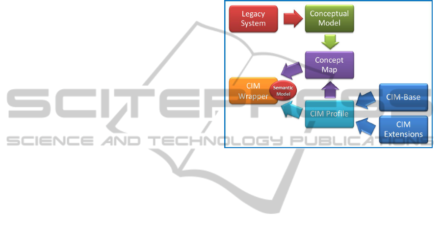
its particular scopes. In Figure 2 it is shown the
adoption process of CIM based in the development
of “CIM Wrappers”.
Figure 2: CIM Adoption Process based on “CIM
Wrappers”.
The first phase in the CIM adoption process, it has
two parallel tasks: the creation of a CIM Profile and
the development of a Conceptual Model of the
Legacy System to integrate.
A CIM Profile is a subset of Classes, Attributes
and Associations of CIM Base Model that
represents the components of the real world selected
for its use in the information systems. The CIM
Profile is obtained by selecting only the concepts
and its relations with other concepts that will be used
in a scheme or architecture of semantic
interoperability for an electric enterprise. For the
concept selection and its relations it is used the
software tool CIMtool (CIMtool, 2013) and the
result must be obtained as Ontology in a format
legible by computer, for example OWL or RDFS
(Scheme) (Espinosa et al., 2011).
The CIM Profile can use native concepts of the
CIM Base Model or the extended concepts during
the Concept Mapping.
The Conceptual Model of a legacy system is a
Model that formally represents the elements that
compose it and the relations among them; according
to the legacy system, this Model must be preferably
created using the paradigm “Object Oriented” and
UML, but in occasions, the relational model can be
applied. This Model is the source of base
information in order to know the meaning of the
SMARTGREENS2014-3rdInternationalConferenceonSmartGridsandGreenITSystems
92
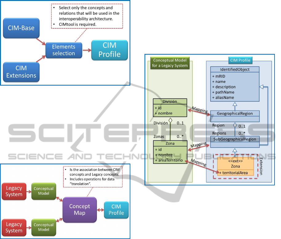
Figure 3: CIM Profile definition.
stored data and managed by the legacy system and it
will allow performing the next stage.
The Concept Map refers to the relations among
defined concepts in the CIM Profile and the stored
concepts by the legacy systems, meaning by this that
it describes the “translation rules” of the data to be
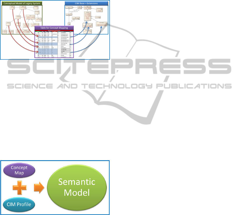
exchanged. Figure 4 shows the process to define the
Concept Map.
Figure 4: CIM Concept Map definition.
For example, the concept “Distribution Division”
stored in the legacy systems in a table of a relational
database, it can be translated in a direct way to
“GeographicalRegion” of CIM, due to the fact that
the CIM description establishes in a rigorous manner
the definition of this Class and it corresponds to the
“Division” hierarchy in the organizational structure
of the enterprise. The concept “Distribution Zone”
can be translated in a direct manner to the CIM
concept “SubGeographicalRegion”. Likewise, the
relation among these two concepts of the enterprise
adequately corresponds to the defined relation in
CIM for this structure, due to the fact that a Division
is composed by Zones and Zones must belong to a
Division.
In the case that CIM does not consider a specific
concept, it is required to define a CIM extension,
without affecting the CIM Base Model, meaning by
this that without altering Classes or Relations among
them. For example, the attribute “Territorial
extension” of a Zone, it could be mapped to an
extension in CIM through a new Class inherited
from “SubGeographicalRegion” which includes all
the attributes that were not identified in the CIM
Base Model.
Figure 5: Example of Concepts Mapping between a legacy
system and CIM.
Figure 5 graphically shows the way in which it must
perform the Concept Mapping among the
Conceptual Model of the legacy system and the
concepts in the CIM Profile defined for the electric
utility. It must stand out the fact that before deciding
to include a CIM extension, all the resources must
be exhausted in order to identify the concept in the
native CIM Classes, because any extension will
perfectly be managed by the internal systems that
know the specific CIM Profile, but any entity,
enterprise or system that comply with the CIM Base
Model it cannot interpret the meaning of the
extensions due to the fact that the specific extensions
are not included in the standards emitted by the IEC.
Due to the relevance of the Concept Map, it is
recommended to use a table that allows to establish
the relations for the concepts translation among the
legacy systems and CIM, in such a way that it serves
as a tool of implementation of the meaning of
information (in bidirectional way), as well as
defining agreements among the development groups
and maintenance of the information systems.
In case that the legacy system does not have a
Conceptual Model and the description of the
information that it contains, this table can be taken
SemanticInteroperabilityforSmartGrid-CIMAdoptionProcess
93
to document the formal definition of each data to
exchange. Likewise, if a specific data is duplicated
among different systems, this table must establish
the only source as origin of this data to keep
consistency of the information and thus avoid a
problem of duplicity to the interoperability context
that is being implemented.
Figure 6: Table for Concept Mapping between legacy
systems and CIM.
Due to the fact that CIM models the concepts that
represent object of the real world of the electric
utility, it is required to have the Semantic Model of
data to share, thus it must have the explicit meaning
of each data and value, as well as the relations
among this data, this conceptual description must be
exhaustive and rigorous with the purpose of
facilitating the communication and the information
exchange among different systems.
In CIM adoption process, the Semantic Model is
obtained from the union of two artifacts, the
Concept Map and the CIM Profile as shown in
Figure 7.
Figure 7: Definition of a Semantic Model – CIM based.
In summary, the development of a “CIM Wrapper”
for a specific legacy system will use (or it will be
based in) the Semantic Model.
3.1 Conceptual Model
The legacy system must expose the concepts that it
stores or manages through its Conceptual Model, it
must establish the meaning of each data to share and
it must be the only source for these concepts in all
the interoperability context and scheme scope. It
must not define more than one information source
for a same concept.
3.2 Concept Map
The Concept Map of legacy systems with the
concepts in CIM Profile established in the mapping
table, it will allows to perform the syntactic and
semantic translation of transported data among
information systems in both ways, from the legacy
system to CIM, and from CIM to legacy systems.
3.3 CIM Profile
The CIM Profile will contain the common
definition, strict and exhaustive, of the information
to exchange among systems through CIM. It is based
in the CIM Base Model and the concepts extensions
(exclusive for a specific utility). It must be in a
legible format for computer because the “CIM
Wrapper” must completely implement it in Classes
of some Object Oriented Programming (OOP)
language for validation, reading and interpretation of
the contained information in messages or files.
3.4 Completeness
The Concept Mapping can only use completely
described concepts in the Conceptual Model of the
legacy system and in the CIM Profile because in the
case of accepting a non described concept, this could
be ambiguous or without common interpretation of
its meaning.
4 RESULTS
Next, some results obtained from applying the CIM
adoption process to CFE legacy systems are
described.
Figure 8 shows three views of a CIM Instance
(real world data) with the organizational structure of
the Distribution Subdirection of CFE. The left box
shows a hierarchical tree that allows to navigate the
components of a Division and its Distribution Zones.
The right box shows the CIM segment that models
these concepts and its relations. Finally, the below
box shows in XML format the same data, where it is
out stood that the “Distribution Division” is
associated to the “GeographicalRegion” Class and
“Distribution Zones” is associated to the
SMARTGREENS2014-3rdInternationalConferenceonSmartGridsandGreenITSystems
94
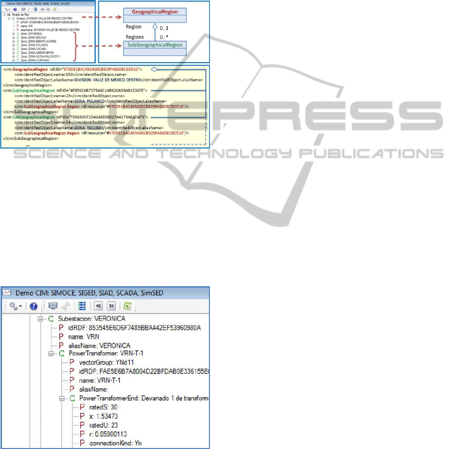
“SubGeographicalRegion” Class. In the example,
the “Polanco” and “Tacuba” Zones are part of the
“Valle de Mexico Downtown Division” (DVMC by
its acronym in Spanish) and an only identifier (in
red) is used to establish the association. This
information comes from the Integral System for
Distribution Management (SIAD by its acronym in
Spanish).
Figure 8: Different views of a CIM Instance for
organizational structure in Distribution Subdirection.
Figure 9 shows that when navigating in the
hierarchical tree, the CIM Instance allows to
consult the electrical information of a Transformer
of “Veronica” Substation, as well as connectivity
topology and geospatial location, which comes from
the GIS for Distribution Network and the electric
details from the On-Line Simulator for Distribution
Power Systems (Espinosa et al., 2010).
Figure 9: CIM Instance showing electrical parameters of
the main power transformer in a Distribution Substation.
The application developed allows consulting
multiple systems and sources of real information,
without inconveniences for the user.
5 CONCLUSIONS
The adoption of CIM and an architecture of
semantic interoperability are key elements that will
allow the information exchange in a standard
manner among systems, with the purpose of
establishing advanced applications that take
advantage of this capacity, such as Demand
Response, Advanced Distribution Automation, Self-
Healing, among others that are emerging and being
defined in the international environment.
Some of the most important electric enterprises
in the world are migrating their data interfaces to
CIM as part of an integral vision of enterprise
degree. Experience shows positive results in the
majority of the cases because the common modeling
by itself minimizes the inconsistency mistakes and
duplicity of information.
REFERENCES
GWAC, GridWise Architecture Council, “GridWise
Interoperability Context-Setting Framework”, March
2008 (http://www.gridwiseac.org).
NIST, NIST Special Publication 1108R2, “NIST
Framework and Roadmap for Smart Grid
Interoperability Standards, Release 2.0”, February
2012.
IEC-EPRI, IEC/PAS 62559, “IntelliGrid Methodology for
Developing Requirements for Energy Systems”,
Publicly Available Specification, Pre-Standard,
Edition 1.0, 2008-01.
EPRI, “Common Information Model Primer”, First
Edition, November 2011.
Parra I., Espinosa A., Arroyo G., Gonzalez S., “Innovative
Architecture for Information Systems for a Mexican
Electricity Utility”, CIGRE 2012 General Meeting,
Paris, France, September 2012.
Espinosa-Reza A., Garcia-Mendoza R, Sierra-Rodríguez
B., “Semantic Interoperability Architecture for the
Distribution Smart Grid in Mexico”, The 11th
WSEAS International Conference on Applied
Informatics and Communications AIC’11, WSEAS
and IAASAT, Florence, Italy, August 23-25, 2011, pp.
204-209. ISBN 978-1-61804-028-2.
Espinosa-Reza A. and Sierra-Rodríguez B., “Towards
Distribution Smart Grid in Mexico”, UCAIug 2011
Summit - CIM Users Group Meeting - Austin 2011,
Austin, Texas, USA, November 15 – 18 2011.
(http://www.ucaiug.org/Meetings/Austin2011/).
Espinosa-Reza A., Quintero-Reyes A., et al., “On-Line
Simulator for Decision Support in Distribution Control
Centers in a Smart Grid Context”, WSEAS
Transactions on Systems and Control, Issue 10,
Volume 5, October 2010, ISSN: 1991-8763.
CIMtool (http://www.cimtool.org), February 2013.
SemanticInteroperabilityforSmartGrid-CIMAdoptionProcess
95
