
A QoS Control Method for Camera Network based People
Detection Systems
Toru Abe
1
, Adrian Agusta
2
, Yuto Mitsuhashi
3
and Takuo Suganuma
1
1
Cyberscience Center, Tohoku University, 2-1-1 Katahira, Aoba-ku, Sendai, 980-8577 Japan
2
Electronics System Development Division, Yamaha Motor Co., Ltd., 2500 Shingai, Iwata, Shizuoka, 438-8501 Japan
3
Graduate School of Information Sciences, Tohoku University, 2-1-1 Katahira, Aoba-ku, Sendai, 980-8577 Japan
Keywords:
Camera Network, People Detection System, QoS Control.
Abstract:
Various people detection systems based on camera networks have been developed, and their services (output
of users’ locations) are utilized in a variety of applications. Usually, each application requires a people de-
tection system to keep its quality-of-service (QoS) at a certain level. However, required system QoS levels
vary widely among different applications, and the QoS requirements of each application range over various
QoS factors, such as the coverage area, resolution, and frequency of users’ locations. Moreover, the trade-
off between QoS factors arises from limitations on the system resources, which fluctuate due to changes in
circumstances. Consequently, it is difficult for such systems to stably fulfill the diverse QoS requirements of
individual applications. To deal with these difficulties, we propose a QoS control method for camera network
based people detection systems. Taking into account the trade-off between several QoS factors under limited
and varied system resources, our method dynamically adjusts system parameters and controls system QoS to
provide each application with users’ locations at a required QoS level. Experimental results indicate that our
method well maintain system QoS for the changes in application requirements and system resources.
1 INTRODUCTION
Recently, various applications which utilize users’ lo-
cations obtained through sensor networks have been
proposed for a variety of fields including security
surveillance, smart home care, environment monitor-
ing, etc. For these purposes, camera network based
people detection systems are widely used (Valera and
Velastin, 2005; Song et al., 2011; Wang, 2013).
In a people detection system based on a camera
network, images captured by cameras are transmit-
ted via a network, users’ locations are estimated on a
server from these images, and then the estimation re-
sults are provided to an application as the system ser-
vice. Usually, the available system resources for com-
munications and computing are limited and varied,
which affect the quality-of-service (QoS) of the peo-
ple detection system, whereas each application utiliz-
ing users’ locations requires the people detection sys-
tem to keep its QoS at a certain level.
To fulfill the various QoS requirements of indi-
vidual applications under limited and varied system
resources, several approaches have been proposed to
camera network based people detection systems. One
of the most popular approaches is the introduction
of hierarchical architecture, which aims at the effec-
tive utilization of limited system resources by local-
izing the communications and computing of lower-
level image data (Micheloni et al., 2008; Karuppiah
et al., 2010). Several approaches reduce consump-
tion of system resources by selecting part of cameras
in the network and assigning tasks to them (Casares
and Velipasalar, 2011; Dieber et al., 2011). Another
approach adaptively adjusts system parameters tak-
ing into account the trade-off between consumption
of the system resources and QoS requirements of the
applications (Hengstler and Aghajan, 2007; Miche-
loni et al., 2008; Wang et al., 2010).
However, required QoS levels for the camera
network based people detection system vary widely
among different applications, and the QoS require-
ments of each application range over various QoS fac-
tors, such as the coverage area, output resolution, and
output frequency of users’ locations. Moreover, the
trade-off between these QoS factors arises from lim-
itations on the system resources, which fluctuate due
to changes in circumstances. Consequently, it is diffi-
cult for such people detection systems to stably fulfill
242
Abe T., Agusta A., Mitsuhashi Y. and Suganuma T..
A QoS Control Method for Camera Network based People Detection Systems.
DOI: 10.5220/0004845202420248
In Proceedings of the 9th International Conference on Computer Vision Theory and Applications (VISAPP-2014), pages 242-248
ISBN: 978-989-758-009-3
Copyright
c
2014 SCITEPRESS (Science and Technology Publications, Lda.)
the diverse QoS requirements of individual applica-
tions under limited and varied system resources.
To deal with these difficulties, we propose a QoS
control method for camera network based people de-
tection systems. Taking into account the trade-off be-
tween QoS factors under limited and varied system
resources, our proposed method dynamically adjusts
system parameters and control system QoS to pro-
vide each application with users’ locations at a re-
quired QoS level. Experimental results indicate that
our method can well adapt system QoS to the changes
in QoS requirements and system resources.
2 CAMERA NETWORK BASED
PEOPLE DETECTION SYSTEM
2.1 System Configuration
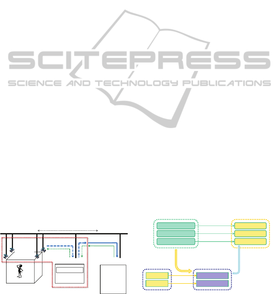
Figure 1 shows the supposed configuration of a people
detection system, which consists of a camera network
and a main server. In this system, images captured
by the cameras are transmitted via the network, users’
locations are estimated on the main server from these
images, and then the estimation results are provided
to an application as services of the system.
Usually, each application requires such a people
detection system to keep its QoS at a certain level.
Those required system QoS levels vary widely among
different applications, and the QoS requirements of
each application range over various QoS factors, such
as the coverage area, accuracy, resolution, delay, and
frequencyof users’ locations (Hengstler and Aghajan,
2007). For example, in security surveillance applica-
tions, the coverage area of users’ locations is an im-
portant QoS factor, although the resolution is rarely
a key issue (Moeslund and Granum, 2001). On the
contrary, in smart home care applications which con-
trol something by users’ locations, the delay and fre-
quency are critical issues, however, the coverage area
people detection system
parameters
images
users’ locations
network
main server
people detection
misc. processes
misc. traffic
target area
camera
network
z security
surveillance
z smart home
care
z environment
monitoring
application
QoS
requirements
Figure 1: Supposed configuration of a people detection sys-
tem based on a camera network.
is less important.
In addition, the trade-off between QoS factors
arises from limitations on the system resources for
communications and computing. Since the available
system resources vary with disturbances (e.g. miscel-
laneous traffic and processes), several QoS factors are
affected by changes in circumstances.
Accordingly, to make people detection systems
more serviceable, they need a QoS control method
which takes into account the trade-off between QoS
factors under limited and varied system resources
while adjusting system parameters, such as the num-
ber of cameras, size of image, frame rate of image,
and network bandwidth.
2.2 Relation Model between QoS
Factors and System Parameters
For the people detection system, there are many QoS
factors and system parameters, which are intricately
interrelated. For example, a QoS factor “coverage
area” is determined by various system parameters
(e.g., the number, placement, and specifications of
cameras), and “output frequency” is affected by the
trade-off between QoS factors and the fluctuation in
available system resources due to not only distur-
bances but also parameter adjustments themselves.
In this paper, we focus on the coverage area, out-
put resolution, and output frequency of users’ loca-
tions as the QoS factors, and the number of cameras,
size of image, frame rate of image as the system pa-
rameters. Furthermore, we simplify the relations be-
tween these QoS factors and system parameters as
summarized in Figure 2. This relation model sup-
poses that the number of cameras and size of image
directly control (i.e. correspond one-to-one with) the
coverage area and output resolution, respectively. On
the other hand, the output frequency is supposed not
affecting QoS factors
(output frequency)
misc. traffic
network resource
server resource
coverage area
output resolution
output frequency
misc. processes
disturbances
system parameters
system resources
QoS factors
fluctuating
available resources
controlling
QoS factors
number of cameras
size of image
frame rate of image
fluctuating
available resources
Figure 2: Simplified relation model between QoS factors
and system parameters of people detection systems.
AQoSControlMethodforCameraNetworkbasedPeopleDetectionSystems
243
only to be controlled by the frame rate of image but
also to be affected by the trade-off between QoS fac-
tors and the system resource fluctuation due to distur-
bances and parameter adjustments.
3 QoS CONTROL OF CAMERA
NETWORK BASED PEOPLE
DETECTION SYSTEMS
3.1 QoS Control Method
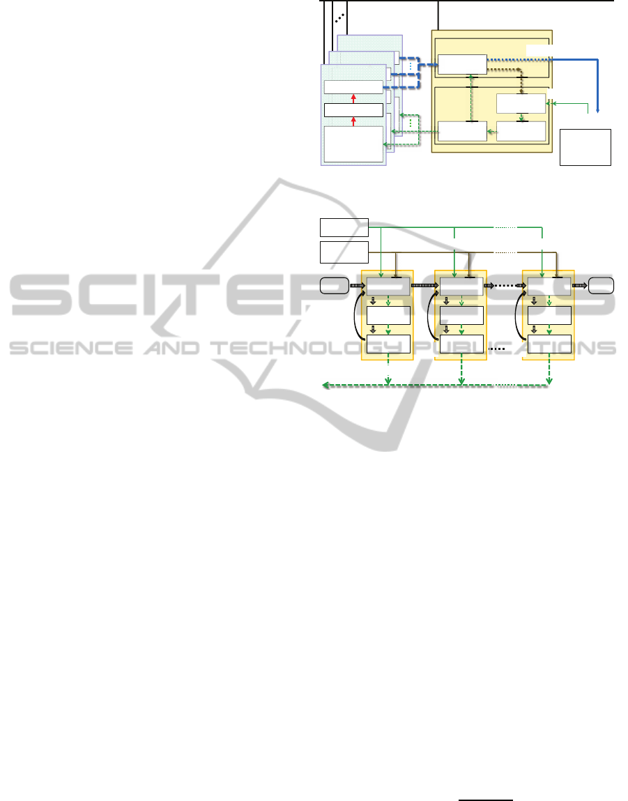
Figure 3 shows the structure of our proposed QoS
control method for camera network based people de-
tection systems. This method is implemented as cam-
eras, people detection part, and QoS control part.
QoS requirements, which specify required lev-
els and priority order for QoS factors, are supplied
from an application in advance. Required levels for
the coverage area, output resolution, and output fre-
quency are measured by the number of cameras, size
of image, and times per unit time, respectively.
With the initial system parameters, the cameras
capture images of the target area, and transmit them to
the people detection part on the main server. The peo-
ple detection part estimates users’ locations from the
receivedimages, and provides the application with the
estimation results as the system output. The QoS con-
trol part compares the QoS requirements of the appli-
cation to the states of the people detection part, which
contain observed levels of the QoS factors. Accord-
ing to the differences in the QoS factors between the
QoS requirements and the people detection states, the
system parameters are adjusted, and then sent to the
cameras and the people detection part.
With the adjusted system parameters, the cameras
and the people detection part change their own set-
tings (i.e., activating or deactivating each individual
camera, setting image size, and setting image frame
rate). Thus, the next series of the processes starts.
3.2 System Parameter Adjustment
Figure 4 shows the flow of system parameter adjust-
ment in our method. Based on the relation model in
2.2, our method adjusts the system parameters in pri-
ority order of the QoS factors. For example, when the
highest priority is assigned to a QoS factor “output
frequency,”a system parameter “frame rate of image”
is iteratively modified to reduce the differencein “out-
put frequency”between the QoS requirementsand the
people detection states. Following this, remaining ad-
justments are carried out for lower priority QoS fac-
parameters
images
network
main server
people detection
camera
network
z security
surveillance
z …
application
estimating
users’ locations
sending
parameters
evaluating
QoS factors
adjusting
parameters
users’ locations
camera N
sending image
capturing image
setting parameters
z (de) activate
z image size
z frame rate
ss
s
s
s
ee
e
e
e
nn
n
n
n
d
d
n
n
dd
d
d
d
ii
n
n
nn
n
n
n
gg
g
g
g
ii
mm
m
m
m
m
m
m
aa
a
a
a
gg
g
g
g
g
g
ee
e
e
e
ss
s
sss
ee
e
eee
nn
n
nnn
d
d
d
n
n
n
dd
d
d
d
d
ii
i
n
n
n
nn
n
n
n
n
gg
g
g
g
g
ii
i
mm
m
mmm
mmm
aa
a
aaa
gg
g
ggg
g
g
g
ee
e
e
e
e
s
s
s
s
s
e
e
e
e
e
n
n
n
n
n
d
n
d
d
d
d
d
i
i
n
n
n
n
n
n
gg
g
ggg
i
i
m
m
m
m
m
m
m
m
a
a
a
a
a
gg
g
ggg
g
g
g
e
e
e
e
e
e
e
e
e
e
e
g
g
g
g
g
e
e
g
g
g
ee
e
e
e
e
g
g
g
ggg
eee
g
g
g
ee
e
eee
eeerr
r
r
r
s
t
t
t
t
t
t
t
ee
e
e
e
e
rr
r
r
r
s
s
t
t
t
ttt
ee
e
eee
rr
r
rrr
s
s
s
t
t
t
t
t
e
e
e
e
e
t
t
t
t
t
t
ee
e
eee
camera 2
sending image
capturing image
setting parameters
z (de) activate
z image size
z frame rate
dd
d
d
d
d
d
i
i
i
i
s
s
s
s
s
s
ee
e
e
e
nn
n
n
n
d
d
d
n
n
dd
d
d
d
d
ii
nn
n
n
n
n
n
gg
g
g
g
ii
mm
m
m
m
m
m
m
aa
a
a
a
gg
g
g
g
g
g
ee
e
e
e
ss
s
s
sss
ee
e
eee
nn
n
nnn
d
d
d
n
n
n
dd
d
ddd
ii
i
nn
n
nnn
n
n
n
gg
g
g
g
g
ii
i
mm
m
mmm
mmm
aa
a
aaa
gg
g
ggg
g
g
g
ee
e
eee
g
g
g
gg
g
g
g
g
g
gg
g
g
g
g
g
aa
a
a
a
aa
a
aaa
cc
c
c
c
aa
a
a
a
p
p
pp
p
p
p
tt
u
u
t
t
uu
u
u
u
rr
r
r
r
ii
nn
n
n
n
g
g
gg
g
g
g
i
i
ii
mm
m
m
m
m
m
m
aa
a
a
a
gg
g
g
g
e
e
ee
e
e
e
cc
c
ccc
aa
a
aaa
p
p
p
pp
p
p
p
p
tt
t
u
u
u
t
t
t
uu
u
u
u
u
rr
r
r
r
r
ii
i
nn
n
nnn
g
g
g
gg
g
g
g
g
i
i
i
ii
i
mm
m
mmm
m
m
m
aa
a
aaa
gg
g
ggg
e
e
e
ee
e
e
e
e
cc
c
ccc
aa
a
aaa
p
p
p
pp
p
ppp
tt
t
uuu
t
t
t
uu
u
uuu
rr
r
rrr
ii
i
nn
n
nnn
g
g
g
gg
g
gg
g
g
iii
ii
i
mm
m
mmm
mmm
aa
a
aaa
gg
g
ggg
g
eee
ee
e
eee
s
s
s
s
s
s
s
e
e
e
e
e
e
e
tt
t
t
t
t
t
t
t
t
t
t
t
t
i
i
i
nn
n
n
n
nn
g
g
g
g
g
g
g
g
g
g
g
g
p
p
p
p
p
p
p
p
p
p
a
aa
a
a
a
a
rr
r
r
r
r
r
a
aa
a
a
a
a
mm
m
m
m
mm
m
m
m
m
e
e
e
e
e
e
e
ss
s
sss
ee
e
eee
tt
t
ttt
tt
t
ttt
ii
i
nn
n
nnn
g
g
g
gg
g
p
p
p
pp
p
ppp
aa
a
aaa
rr
r
rrr
aa
a
aaa
mm
m
mmm
mmm
ee
e
eee
z
z
z
(
(
(
(
(
(
dd
d
d
d
e
e
e
))
)
)
)
aa
a
a
a
cc
c
c
c
tt
t
t
t
ii
vv
i
i
vv
v
v
v
a
a
a
a
a
tt
zz
z
z
z
z
(((
(
(
(
dd
d
ddd
eee
))
)
)))
aa
a
aaa
cc
c
ccc
tt
t
ttt
ii
i
v
v
v
i
i
i
vv
v
v
v
v
aa
a
a
a
a
tt
t
ss
s
s
s
ee
e
e
e
tt
t
t
t
tt
t
t
t
ii
nn
n
n
n
gg
g
g
g
g
g
g
pp
pp
p
p
p
a
a
a
a
a
rr
r
r
r
a
a
a
a
a
mm
m
m
m
m
m
m
ee
e
e
e
tt
t
t
t
ee
e
e
e
rr
r
r
r
s
s
ss
s
s
s
s
ee
e
eee
tt
t
t
t
t
tt
t
t
t
t
ii
i
nn
n
nnn
gg
g
ggg
g
g
g
p
p
p
pp
p
p
p
p
aa
a
a
a
a
rr
r
r
r
r
aa
a
a
a
a
mm
m
mmm
m
m
m
ee
e
eee
tt
t
ttt
ee
e
eee
rr
r
rrr
s
s
s
ss
s
sss
ee
e
eee
tt
t
ttt
tt
t
ttt
ii
i
nn
n
nnn
gg
g
ggg
ggg
p
p
p
pp
p
ppp
aa
a
aaa
rr
r
rrr
aa
a
aaa
mm
m
mmm
mmm
ee
e
eee
tt
t
ttt
ee
e
eee
rr
r
rrr
s
s
s
((
(
(
(
dd
d
d
d
e
e
e
e
e
))
)
)
)
a
a
a
a
a
c
c
c
c
c
tt
t
t
t
ii
v
i
i
v
v
v
v
v
a
a
a
a
a
tt
t
t
t
e
e
e
e
e
camera 1
transmitting image
capturing image
setting parameters
z (de) activate
z image size
z frame rate
l
u
a
t
i
justin
QoS
control
requirements
us
i
cation
parameters
states
Figure 3: Structure of the proposed QoS control method for
camera network based people detection systems.
evaluating
QoS factors
adjusting
parameters
sending
parameters
evaluating
QoS factors
adjusting
parameters
sending
parameters
evaluating
QoS factors
adjusting
parameters
sending
parameters
iteration for
1st priority
QoS factor
application
people
detection
2nd
priority
m-th
priority
START
END
atin
g
requirements (required levels and priority order for QoS factors)
adjusted parameters
ating
ating
states (1st, 2nd, …, and m-th priority QoS Factors)
Figure 4: Flow of system parameter adjusting.
tors. Every adjustment is iterated until the difference
in its target QoS factor does not decrease or the dif-
ferences in higher priority QoS factors increase.
As described in 2.2, we suppose that the QoS fac-
tors are controlled directly by the system parameters.
However, as the number of cameras and/or the size
of image increase, the output frequency is affected by
the QoS factor trade-off and the system resource fluc-
tuation. Therefore, it is difficult to control the QoS
factors directly in those cases.
To achieve appropriate QoS control, we approxi-
mate the relation between the QoS factors. Suppose
that all cameras are set to the same size and the same
frame rate of image. If the people detection part out-
puts a set of users’ locations after receiving the im-
ages from all activated cameras, then the maximum
output frequency (OF) is inversely proportional to the
cover area (CA) controlled by the number of cameras
and the output resolution (OR) controlled by the size
of image. Consequently, the relation between these
QoS factors is expressed in
OF =
α
CA× OR
, (1)
where α is a coefficient depending on the system per-
formance. By substituting observed levels of the QoS
factors into Eq. (1) in order of their priorities, target
VISAPP2014-InternationalConferenceonComputerVisionTheoryandApplications
244
levels can be determined for lower priority QoS fac-
tors, and amounts for system parameter adjustments
can be estimated from these results. Since α varies
with the available system resources, its initial value
is set by the calibration of a target people detection
system, and then updated iteratively by the observed
levels of CA, OR, and OF.
4 EXPERIMENTS
4.1 Experimental Environment
To demonstrate the effectiveness of our proposed
method, we conducted QoS control experiments on
a camera network based people detection system.
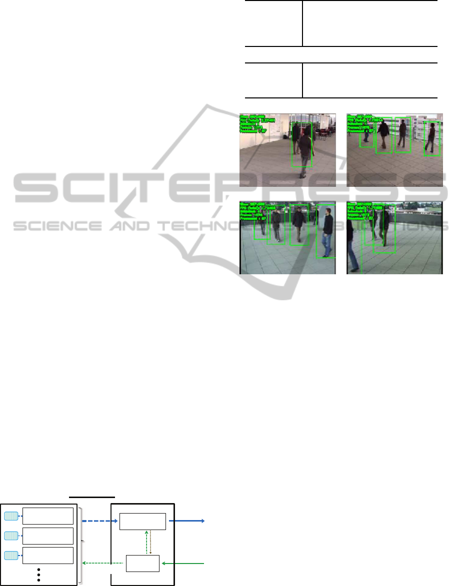
Figure 5 shows the structure of the prototype sys-
tem used in the experiments. This system consists of a
main server and an image server, which are connected
with each other through 100MbpsEthernet. The spec-
ifications of those servers are listed in Table 1. The
main server has a QoS control module and a people
detection module, while the image server has camera
simulation modules. Those modules are implemented
in C++. To manage experimental conditions, instead
of an actual camera network, the image server (each
camera simulation module) transmits images to the
main server (people detection module).
The QoS control module is manually provided
with QoS requirements (the required levels and pri-
ority order for the coverage area (CA), output resolu-
tion (OR), and output frequency (OF)). According to
the states obtained from the people detection module,
system parameters (the number of cameras, size of
image, and frame rate of image) to fulfill the QoS re-
quirements are computed in the QoS control module
and sent to other modules. The people detection mod-
ule is based on “
pedestrian_detect
” in “OpenCV-
2.4.3 GPU demos pack” (Bradski et al., 2012) which
is modified to receive multiple image sequences, esti-
mate users’ locations from them, and change its own
setting with parameters from the QoS control module.
In the camera simulation modules, videos captured
images
users’
locations
100bps Ethernet
QoS
requirements
main server
people detection
module
QoS control
module
states
parameters
image server
camera simulation
module
video
camera simulation
module
video
camera simulation
module
video
parameters
Figure 5: Structure of the prototype system.
Table 1: Specifications of servers.
main server
CPU Intel Core i7-870 (2.93GHz)
GPU NVIDIA GeForce GT 430
memory
8GB
OS Windows 7 Professional x64
image server
CPU Intel Core i5-560M (2.66GHz)
memory
8GB
OS Windows 7 Professional x64
video1 video2
video3 video4
Figure 6: Examples of people detection results by the proto-
type system (green rectangles represent detected locations).
with multi-camera (CVLab-EPFL, 2012) are used for
transmission, where the size and frame rate of images
are changed with parameters from the QoS control
module (the original size and frame rate of each video
are 360× 288 pixels and 25 fps, respectively).
Examples of people detection results (users’ loca-
tions) by the prototype system are shown in Figure 6.
4.2 Experimental Results
4.2.1 Baseline Performance
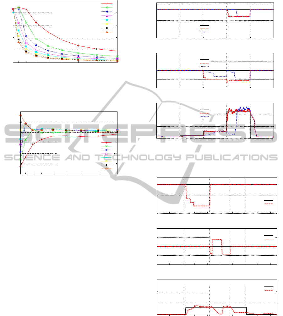
Firstly, we carried out experiments to evaluate the
baseline performance of the prototype system.
In the experiments, output frequency (OF) is eval-
uated by varying the number of cameras and the size
of image. The number of activated cameras (cam-
era simulation modules transmitting images) is varied
from one to eight, and the size of transmitted image
is varied from 144× 115 to 720× 576 pixels (i.e., the
magnification for the original size 360× 288 pixels is
varied from 0.4 to 2). The frame rate of each camera
is fixed at 25 fps. Experimental results are summa-
rized in Figure 7. Since the people detection module
AQoSControlMethodforCameraNetworkbasedPeopleDetectionSystems
245
0
5
10
15
20
25
144x115(0.4)
216x173(0.6)
288x230(0.8)
360x288(1.0)
432x346(1.2)
504x403(1.4)
576x461(1.6)
648x518(1.8)
720x576(2.0)
output frequency (OF) [times/s]
size of image (magnification) [pixels]
number of cameras 1
2
3
4
5
6
7
8
Figure 7: Output frequency (OF) by varying the number of
cameras and the size of image.
0.0×10
0
5.0×10
5
1.0×10
6
1.5×10
6
2.0×10
6
2.5×10
6
3.0×10
6
144x115(0.4)
216x173(0.6)
288x230(0.8)
360x288(1.0)
432x346(1.2)
504x403(1.4)
576x461(1.6)
648x518(1.8)
720x576(2.0)
α = CA × OR × OF [pixels/s]
size of image (magnification) [pixels]
number of cameras 1
2
3
4
5
6
7
8
Figure 8: Coefficient α in Eq. (1) estimated from observed
levels of the QoS factors.
outputs a set of users’ locations after receiving the im-
ages from all activated cameras, OF is not more than
a frame rate of 25 fps. Naturally, because of limita-
tions on the system resources for communicationsand
computing, OF decreases as the number of cameras
and/or the size of image increase.
Multiplying the individual results by the number
of cameras and the size of image, we compute the
number of pixels processed on the main server per
unit time, which correspond α = CA × OR × OF in
Eq. (1). Obtained results are summarized in Figure 8.
Except for cases where the number of cameras and the
size of image are small, obtained CA × OR× OF are
fairly constant regardless of the number of cameras or
the size of image. Consequently, by calibrating the
system for a certain number of cameras in advance,
the obtained CA×OR× OF can be used for adjusting
system parameters as the initial value of α in Eq. (1).
4.2.2 Adaptation to QoS Requirement Changes
To demonstrate the effectiveness of our proposed
method in adapting to QoS requirement changes, we
0
5
10
0 50 100 150 200 250
(a) (b) (c) (d)
coverage area (CA) [cameras]
elapsed time [s]
required level
ovserved value (with cal.)
ovserved value (w/o cal.)
0
0.5
1
1.5
2
0 50 100 150 200 250
(a) (b) (c) (d)
resolution (OR) [mag.]
elapsed time [s]
required level
ovserved value (with cal.)
ovserved value (w/o cal.)
0
10
20
30
0 50 100 150 200 250
(a) (b) (c) (d)
frequency (OF) [times/s]
elapsed time [s]
required level
ovserved value (with cal.)
ovserved value (w/o cal.)
Figure 9: Adaptation to QoS requirement changes (required
level for OF is changed at (a), (b), (c), and (d)).
0
5
10
0 20 40 60 80 100 120 140 160 180
(e) (f) (g) (h)
coverage area (CA) [cameras]
elapsed time [s]
required level
ovserved value (with cal.)
0
0.5
1
1.5
2
0 20 40 60 80 100 120 140 160 180
(e) (f) (g) (h)
resolution (OR) [mag.]
elapsed time [s]
required level
ovserved value (with cal.)
0
10
20
30
0 20 40 60 80 100 120 140 160 180
(e) (f) (g) (h)
frequency (OF) [times/s]
elapsed time [s]
required level
ovserved value (with cal.)
Figure 10: Adaptation to changes in required level for OF
and priority order for QoS factors at (e), (f), (g), and (h).
conducted QoS control experiments.
Observed levels of CA, OR, and OF by changing
QoS requirements are shown in Figure 9. In this ex-
periment, the required level for OF is changed from 1
time/s to (a) 2 times/s at 48s → (b) 6 times/s at 99s →
VISAPP2014-InternationalConferenceonComputerVisionTheoryandApplications
246
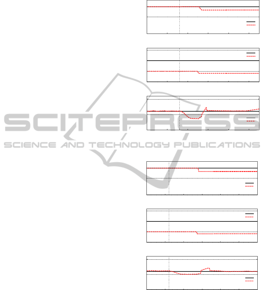
(c) 23 times/s at 149s → (d) 1 time/s at 199s, whereas
the required levels for CA and OR are fixed at 8 cam-
eras and 1 magnification, respectively, and the prior-
ity order for QoS factors is fixed to OF>CA>OR.
The QoS control is carried out with or without the
prototype system calibration where CA× OR×OF =
2.07× 10
6
pixels/s is obtained for a set of eight cam-
eras as the initial value of α in Eq. (1).
From (a) to (b) in Figure 9, since the required level
for OF is rather low, the system parameters can be ad-
justed to its increase without the influence on CA or
OR, and consequently all requirements for the QoS
factors are fulfilled. From (b) to (c), the system pa-
rameters can be adjusted to an increase in the required
level for OF, however, the lowest priority QoS factor
OR is lowered due to limitations on the system re-
sources. From (c) to (d), the system parameters are
adjusted to a further increase in the required level for
OF by decreasing the second priority QoS factor CA
in addition to OR. As can be seen from Figure 9, the
QoS control with the calibration adapts to the QoS re-
quirement changes more quickly than the QoS control
without the calibration.
Figure 10 shows the experimental result of the
QoS control with the calibration by changing the
priority order for QoS factors. In this experiment,
the priority order is changed from OR>OF>CA to
(f) OF>CA>OR at 83s → (g) CA>OR>OF at 116s.
Meanwhile, the required levels for CA and OR are
fixed at 8 cameras and 1 magnification, respectively,
and the required level for OF is changed from 1 time/s
to (e) 7 times/s at 45s → (h) 1 time/s at 141s.
From (e) to (f), by decreasing the lowest priority
QoS factor CA, the QoS control adapts to an increase
in the required level for the highest priority QoS factor
OF. From (f) to (g), because the lowest priority QoS
factor changes from CA to OR, the QoS control keeps
OF at its required level by decreasing OR instead of
CA. From (g) to (h), since OF is given the lowest
priority, the QoS control keeps CA and OR at their
required levels by decreasing OF.
These results indicate that our proposed method
can keep the QoS factors of the people detection sys-
tem at specified QoS levels in specified priority order.
4.2.3 Adaptation to System Resource Changes
To demonstrate the effectiveness of our proposed
method in adapting to system resource changes, QoS
control experiments were conducted.
In the experiments, the required levels for CA,
OR, and OF are fixed at 8 cameras, 1 magnification,
and 6 times/s, respectively, and, the priority order for
QoS factors is fixed to OF>CA>OR.
0
5
10
0 10 20 30 40 50
(a)
coverage area (CA) [cameras]
elapsed time [s]
required level
ovserved value (with cal.)
0
0.5
1
1.5
0 10 20 30 40 50
(a)
resolution (OR) [mag.]
elapsed time [s]
required level
ovserved value (with cal.)
0
5
10
0 10 20 30 40 50
(a)
frequency (OF) [times/s]
elapsed time [s]
required level
ovserved value (with cal.)
Figure 11: Adaptation to a server resource change at (a).
0
5
10
0 5 10 15 20 25 30
(b)
coverage area (CA) [cameras]
elapsed time [s]
required level
ovserved value (with cal.)
0
0.5
1
1.5
0 5 10 15 20 25 30
(b)
resolution (OR) [mag.]
elapsed time [s]
required level
ovserved value (with cal.)
0
5
10
0 5 10 15 20 25 30
(b)
frequency (OF) [times/s]
elapsed time [s]
required level
ovserved value (with cal.)
Figure 12: Adaptation to a network resource change at (b).
Figure 11 shows the experimental result, where a
CPU load of 50% is imposed on the main server by
a CPU load generator program in addition to loads
of the QoS control module and the people detection
module. On the other hand, Figure 12 shows the ex-
perimental result, where 66.6Mbps of traffic from a
traffic generator program is imposed on the network
AQoSControlMethodforCameraNetworkbasedPeopleDetectionSystems
247

in addition to the traffic between the QoS control, peo-
ple detection, and camera simulation modules.
Currently, since neither the CPU load nor the net-
work traffic is monitored directly by the prototype
system, the server resource fluctuation due to an ad-
ditional CPU load ((a) at 16s in Figure 11) or the net-
work resource fluctuation due to additional network
traffic ((b) at 6s in Figure 12) is detected as a decrease
in OF. To keep the highest priority QoS factor OF at
its required level, the QoS control decreases the low-
est priority QoS factor OR in both the experiments.
However, as OF cannot reach its required level in both
cases, the QoS control decreases the second priority
QoS factor CA in addition to OR.
These results indicate that our proposed method
can adapt to the fluctuation in the available system
resources for communications and computing.
5 CONCLUSIONS
In this paper, we have proposed a QoS control method
for camera network based people detection systems.
Taking into account the trade-off between several
QoS factors under limited and varied system re-
sources, our proposed method dynamically adjusts
system parameters and controls system QoS. Through
the experiments, we illustrated the effectiveness of
our method in maintaining individual QoS factors
for the changes in QoS requirements and system re-
sources. Those results demonstrate that our method
can keep the QoS factors of the people detection sys-
tem at specified QoS levels in specified priority order.
Consequently, our method can be expected to make
the people detection system more serviceable for var-
ious applications utilizing users’ locations.
Currently, our proposed method controls the cov-
erage area, output resolution, and output frequency
of users’ locations as the QoS factors by adjusting
the number of cameras, size of image, and frame rate
of image as the system parameters through simplified
their relation model. In future work, we would like
to investigate extending our method to various other
QoS factors (e.g., output accuracy, output delay, and
power consumption), system parameters (e.g., camera
placement, image coding, and network bandwidth),
and more precise models of their relations.
ACKNOWLEDGEMENTS
This work was supported in part by the Japan Society
for the Promotion of Science (JSPS) under a Grant-
in-Aid for Scientific Research (C) (No.23500201).
REFERENCES
Bradski, G. et al. (2012). OpenCV | Free Sci-
ence & Engineering software downloads at Source-
Forge.net.
http://sourceforge.net/projects/
opencvlibrary/files/opencv-win/2.4.3/
. On-
line; accessed 1-Aug.-2013.
Casares, M. and Velipasalar, S. (2011). Adaptive method-
ologies for energy-efficient object detection and track-
ing with battery-powered embedded smart cam-
eras. IEEE Trans. Circuits Syst. Video Tec hnol.,
21(10):1438–1452.
CVLab-EPFL (2012). Multi-camera pedestrians video |
CVLAB.
http://cvlab.epfl.ch/data/pom
. On-
line; accessed 1-Aug.-2013.
Dieber, B., Micheloni, C., and Rinner, B. (2011). Resource-
aware coverage and task assignment in visual sensor
networks. IEEE Trans. Circuits Syst. Video Tec hnol.,
21(10):1424–1437.
Hengstler, S. and Aghajan, H. (2007). Application-oriented
design of smart camera networks. In First ACM/IEEE
Int. Conf. Distrib. Smart Cameras, pages 12–19.
Karuppiah, D. R., Grupen, R. A., Zhu, Z., and Han-
son, A. R. (2010). Automatic resource allocation in
a distributed camera network. Mach. Vision Appl.,
21(4):517–528.
Micheloni, C., Lestuzzi, M., and Foresti, G. L. (2008).
Adaptive video communication for an intelligent
distributed system: Tuning sensors parameters for
surveillance purposes. Mach. Vision Appl., 19(5-
6):359–3733.
Moeslund, T. B. and Granum, E. (2001). A survey of com-
puter vision-based human motion capture. Comput.
Vis. Image Understanding, 81(3):231–268.
Song, B., Ding, C., Kamal, A. T., Farrell, J. A., and Roy-
Chowdhury, A. K. (2011). Distributed camera net-
works. IEEE Signal Process. Mag., 28(3):20–31.
Valera, M. and Velastin, S. A. (2005). Intelligent distributed
surveillance systems: a review. IEE Proc. Vis, Image
Signal Process., 152(2):192–2004.
Wang, X. (2013). Intelligent multi-camera video surveil-
lance: A review. Pattern Recognit. Lett., 34(1):3–19.
Wang, Y., Velipasalar, S., and Casares, M. (2010). Coop-
erative object tracking and composite event detection
with wireless embedded smart cameras. IEEE Trans.
Image Process., 19(10):2614–2633.
VISAPP2014-InternationalConferenceonComputerVisionTheoryandApplications
248
