
Towards Relative Altitude Estimation in Topological Navigation Tasks
using the Global Appearance of Visual Information
Francisco Amor´os, Luis Pay´a, Oscar Reinoso, David Valiente and Lorenzo Fern´andez
Systems Engineering and Automation Department, Miguel Hern´andez University,
Avda. de la Universidad s/n, 03202, Elche, Alicante, Spain
Keywords:
Global-appearance Descriptors, Topological Navigation, Altitude Estimation, Zooming, Camera Coordinate
Reference System, Orthographic View, Unit Sphere Image.
Abstract:
In this work, we present a collection of different techniques oriented to the altitude estimation in topological
visual navigation tasks. All the methods use descriptors based on the global appearance of the scenes. The
techniques are tested using our own experimental database, which is composed of a set of omnidirectional
images captured in real lightning conditions including several locations and altitudes. We use different rep-
resentations of the visual information, including the panoramic and orthographic views, and the projection of
the omnidirectional image into the uni sphere. The experimental results demonstrate the effectiveness of some
of the techniques.
1 INTRODUCTION
The richness of the information that visual systems
provide and the multiple possibilities of configura-
tions and applications make them a popular sensing
mechanism in robotic navigation tasks. Among all
the of visual sensors, we focus our work in omnidi-
rectional vision. In the literature, we can find numer-
ous examples where omnidirectional visual systems
are employed in navigation tasks, such as (Winters
et al., 2000).
Classical research into mobile robots equipped
with vision systems have focused on local features
descriptors, extracting natural or artificial landmarks
from the image. With this information, it is possi-
ble to obtain image descriptors useful in navigation
tasks. As an example, (Lowe, 1999) proposes SIFT,
and (Bay et al., 2006) presents SURF.
On the other hand, global appearance approaches
propose processing the image as a whole, without lo-
cal feature extraction. These techniques have demon-
strated a good accuracy on the floor plane navigation
in both location and orientation estimation. (Chang
et al., 2010) and (Pay´a et al., 2010) include some ex-
amples.
Nowadays, Unmanned Aerial Vehicles (UAVs)
are becoming very popular as a platform in the field of
robotic navigation research. In this sense, we can find
in (Mondrag´on et al., 2010), (Han et al., 2012) and
(Wang et al., 2012) different approaches that study
the motion and attitude of UAVs using visual systems.
Specifically, these works are based on image feature
extraction or image segmentation in order to extract
valuable information of scenes to create and improve
navigation systems.
The aim of this paper is to extend the use of the
global appearance descriptors to navigation applica-
tions where the altitude of the mobile robot changes.
For that purpose, we suppose that the UAV is sta-
bilized and the visual sensor has the same attitude,
which corresponds with the perpendicular regarding
the floor plane. In particular, we study the ability of
altitude estimation using global appearance descrip-
tors.
The algorithms presented in this work are tested
using our own experimental database, composed of
omnidirectional images acquired with a catadioptric
vision system composed of an hyperbolic mirror and
a camera.
From the omnidirectional scenes, we represent the
visual information using different projections. Specif-
ically, the panoramic and orthographic views, and the
projection over the unit sphere (Roebert et al., 2008).
The descriptors used and the altitude estimation tech-
niques depends on the type of scene projection.
The remainder of the paper is structured as fol-
lows: Section 2 includes the global appearance de-
scriptors we use in order to compress the visual in-
194
Amorós F., Payá L., Reinoso O., Valiente D. and Fernández L..
Towards Relative Altitude Estimation in Topological Navigation Tasks using the Global Appearance of Visual Information.
DOI: 10.5220/0004746301940201
In Proceedings of the 9th International Conference on Computer Vision Theory and Applications (VISAPP-2014), pages 194-201
ISBN: 978-989-758-003-1
Copyright
c
2014 SCITEPRESS (Science and Technology Publications, Lda.)

formation. Section 3 discusses the different methods
used with the purpose of finding the relative altitude
between images acquired in a same point in the floor
plane. In the next section, the database used in the
experiments is presented. Section 5 gathers the ex-
perimental results, and finally, the main conclusions
are included in section 6.
2 GLOBAL APPEARANCE
DESCRIPTORS
In this section we include some techniques to extract
the most relevant information from images to build a
descriptor. In particular, we present descriptors based
on the global appearance of scenes. These descrip-
tors are computed working with the image as a whole,
avoiding segmentation or landmarks extraction, try-
ing to keep the amount of memory to a minimum.
Specifically, the three descriptors included are
based on the representation of the visual information
in the frequency domain using the Fourier Transform.
2.1 Fourier Signature
The Fourier Signature is defined in (Menegatti et al.,
2004). This work demonstrates that it is possible to
represent an image using the Discrete Fourier Trans-
form of each row. So, we can expand each row of an
image {a
n
} = {a
0
, a
1
, . . . , a
N−1
} into the sequence of
complex numbers {A
n
} = {A
0
, A
1
, . . . , A
N−1
}:
{A
n
} = F [{a
n
}] =
N−1
∑
n=0
a
n
e
− j
2π
N
kn
, k = 0, . . . , N −1.
(1)
Taking profit of the Fourier Transform properties,
we just keep the first coefficients to represent each
row since the most relevant information concentrates
in the low frequency components of the sequence.
Moreover, when working with omnidirectional im-
ages, the modulus of the Fourier Transform of the im-
age’s rows is invariant against rotations in the perpen-
dicular plane of the image.
2.2 2D Fourier Transform
When we have an image f(x,y) with Ny rows and Nx
columns, the 2D discrete Fourier Transform is defined
through:
F [ f(x, y)] = F(u, v) =
1
N
y
N
x
−1
∑
x=0
N
y
−1
∑
y=0
f(x, y)e
−2πj
ux
N
x
+
vy
N
y
,
u = 0, . . . , N
x
− 1, v = 0, . . . , N
y
− 1.
(2)
The components of the transformed image are
complex numbers so it can be split in two matrices,
one with the modules (power spectrum) and other
with the angles. The most relevant information in
the Fourier domain concentrates in the low frequency
components. Another interesting property when we
work with panoramic images is the rotational invari-
ance, which is reflected in the shift theorem:
F [ f(x− x
0
, y− y
0
)] = F(u, v) · e
−2π j
ux
0
N
x
+
vy
0
N
y
,
u = 0, . . . , N
x
− 1, v = 0, . . . , N
y
− 1.
(3)
According to this property, the power spectrum of
the rotated image remains the same of the original im-
age and only a change in the phase of the components
of the transformed image is produced. The variation
in the phase values depends on the shift on the x-axis
(x
0
) and the y-axis (y
0
).
2.3 Spherical Fourier Transform
Omnidirectionalimages can be projected onto the unit
sphere when the intrinsic parameters of the vision sys-
tem are known. Being θ ∈ [0, π] the colatitude angle,
and φ ∈ [0, 2π) the azimuth angle, the projection of
the omnidirectional image in the 2D sphere can be ex-
pressed as f(θ, φ). In (Driscoll and Healy, 1994), it is
shown that the spherical harmonic functions Y
lm
form
a complete orthonormal basis over the unit sphere.
Any square integrable function defined on the sphere
f ∈ L
2
(s
2
) can be represented by its spherical har-
monic expansion as:
f(θ, φ) =
∞
∑
l=0
l
∑
m=−l
b
f
lm
Y
lm
(θ, φ), (4)
with l ∈ N and m ∈ Z, |m| ≤ l.
b
f
lm
∈ C denotes the
spherical harmonic coefficients, and Y
lm
the spherical
harmonic function of degree l and order m defined by
Y
lm
(θ, φ) =
s
2l + 1
4π
(l − m)!
(l + m)!
P
m
l
(cosθ)e
imθ
, (5)
where P
m
l
(x) are the associated Legendre functions.
As with the Fourier Signature and 2D Fourier
Transform, it is possible to obtain a rotationally
invariant representation from the Spherical Fourier
Transform. Considering B the band limit of f , the
coefficients of e = (e
1
, ..., e
B
) are not affected by 3D
rotations of the signal, where
e
l
=
s
∑
|m|≤l
|
b
f
lm
|
2
. (6)
TowardsRelativeAltitudeEstimationinTopologicalNavigationTasksusingtheGlobalAppearanceofVisualInformation
195

In (Makadia et al., 2004), (McEwen and Wiaux,
2011), (Schairer et al., 2009), (Huhle et al., 2010) and
(Schairer et al., 2011) it is possible to find more infor-
mation and examples of applications of the Spherical
Fourier Transform in navigation tasks.
3 ALTITUDE ESTIMATION
METHODS
This section details the different techniques used to
obtain a measurement of the relative altitude of a set
of images captured from the same point in the floor
plane. We make use of functions included in the Mat-
lab toolbox OCamCalib (Scaramuzza et al., 2006) to
calibrate the camera and to obtain different views of
the visual information from the omnidirectional im-
age.
3.1 Central Cell Correlation of
Panoramic Images
Many algorithms are based on the panoramic view of
the omnidirectional image as a input information of
the navigation system, e.g. (Briggs et al., 2004).
In a panoramic image, the most distinctive infor-
mation is usually located in the central rows of the
scene, specially in outdoor environments, where the
lower angles usually correspond to the floor, and the
higher angles to the sky. Moreover, if a change in
the altitude of the robot is produced both upwards or
downwards, this area is less likely to go out of the
camera field of view.
Taking this into account, we propose to compare
the central rows of two images to estimate its rela-
tive altitude. For that purpose, the algorithm com-
putes the descriptor of a cell that includes the middle
image rows, and repeat the process for different cells
situated above and below the first one. In the Fig. 1
we can see an example of an image and different cells
applied to the scene. The central cell is in bold, and
we can also appreciate the additional cells above and
below it.
Figure 1: Panoramic Image Cells used to find the relative
altitude between two scenes.
When we have captured an image from the same
(x,y) coordinate but with different altitude, we com-
pute the descriptor of its central cell, and compare it
with all the descriptors obtained from the cells of the
first image (that acts as a reference image). The com-
parison is carried out by means of the Euclidean dis-
tance.
We match the central cell of the new image with
all the cells of the reference image using the minimum
descriptor distance as a criteria. The comparison with
a lower image distance denotes a higher correlation,
and the height (d) associated with the reference im-
age cell selected denotes the relative altitude of both
images, indicated in pixels.
3.2 FFT2D Vertical Phase Lag
As stated in Section 2.2, the 2D Fourier Transform
let us to detect a change in the order of both rows and
columns of a matrix. Specifically, as Eq. 3 indicates, a
circular rotation of the rows or columns of the original
information produces a change in the phase informa-
tion of the Fourier Transform components, since the
power spectrum remains without change.
When we work with panoramic images, a rotation
of the scene produces a circular shift in the rows of
the scene. For that reason, we are able to estimate the
phase lag between two rotated images captured in the
same position.
Our aim is to extend this property to vertical vari-
ations. However, we can not extrapolate the idea di-
rectly. Unlike a rotation around the perpendicular fo-
cal axis of the camera, a change in the robot altitude
does not only produce the shift of the information in-
cluded in the panoramic image, since the movement
also supposes a change in the camera field of view.
So, new information is introduced in the current im-
age at the same time that some rows disappear in the
lower or higher part of the panoramic image depend-
ing on the vertical movement direction. Therefore, it
is not exactly a circular rotation of the image rows,
reason why it introduces some changes in the Fourier
transform coefficients.
Moreover, if a change in the orientation in the
camera is produced at the same time that a variation
in its altitude, the effects of both changes are intro-
duced in the Fourier coefficients’ phase, being diffi-
cult to discern whether the phase difference between
the transforms of tho images has been produced be-
cause of the vertical or the rotation movement.
Since this work is focused in the altitude estima-
tion, we suppose that the panoramic images have the
same orientation.
In order to estimate the vertical lag between two
VISAPP2014-InternationalConferenceonComputerVisionTheoryandApplications
196

(a) Altitude=125cm(h = 1) (b) Altitude=290cm(h = 12)
Figure 2: Example of images captured at three different al-
titudes in the same location.
scenes captured from the same (x,y) location, we use
the phase of the Fourier coefficients. Specifically, we
use a submatrix with the first N
F
×N
F
elements of the
2D Transform phase, denoted by ph(F
N
F
×N
F
).
As stated before, a vertical shift in the space do-
main produces a phase lag in the frequency space. We
can artificially simulate the effect of a vertical rotation
in the phase of the Fourier coefficients. Being R the
vertical rotation in degrees, the submatrix phase of the
rotated coefficients ph(F
N
F
×N
F
)
R
can be estimated as:
ph(F
N
F
×N
F
)
R
= ph(F
N
F
×N
F
) + R·VRM (7)
with VRM the Vertical Rotation Matrix, that can
be defined as:
VRM =
0 0 ··· 0
1 1 ··· 1
2 2 ··· 2
.
.
.
.
.
.
.
.
.
.
.
.
N
F
N
F
··· N
F
N
F
×N
F
(8)
Given a reference image, we estimate
ph(F
N
F
×N
F
)
R
for R = [−180
◦
, −180
◦
+∆R, . . . , 180
◦
].
In the experiments, we define ∆R = 0.5
◦
.
When an new image arrives, we compute
ph(F
N
F
×N
F
) and compare it with the different
ph(F
N
F
×N
F
)
R
of the reference image.
The R where the difference is minimum denotes
the relative altitude between images.
3.3 Zooming of the Orthographic View
In this technique, we propose to make use of image
zooming with the purpose of measuring the vertical
shift of a UAV. In (Amor´os et al., 2013), a method to
obtain the topological distance between images fol-
lowing a route by means of zooming is developed.
However, we can not extract valuable information
about altitude zooming the omnidirectional image di-
rectly. We need a representation of the visual in-
formation perpendicular to the movement movement.
For that reason, we use the orthographic view of the
scene. In (Maohai et al., 2013) and (Bonev et al.,
2007) we can find examples where orthographic view
is used in robot navigation tasks.
We vary the distance of the plane where the om-
nidirectional image is projected to obtain different
zooms of the bird-eye view by changing the focal dis-
tance.
After obtaining the orthographic view, we need to
describe the scene using two different descriptors. We
can use both the Fourier Signature and the 2D Fourier
Transform to describe the image.
We estimate the vertical distance between two im-
ages using the focal difference. First, we obtain the
orthographic view of the reference image using sev-
eral focal distances. The relative altitude of a new im-
age captured in the same position in the floor plane,
we project the bird-eye view of the new scene with a
fixed focal, and compute its image distance with every
projection of the reference view.
3.4 Coordinate Reference System (CRS)
of the Camera
As shown in (Valiente et al., 2012), given an image,
it is possible to modify the coordinate reference sys-
tem (CRS) of the camera using the epipolar geometry,
obtaining a new projection of the original image. The
reprojected image, that uses the new CRS, reflects the
movement of the camera.
Fist of all, we estimate the coordinates of the im-
age in the real world in pixels. m = [m
x
pix
, m
y
pix
] are
the pixel coordinates regarding the omnidirectional
image center. The camera calibration allows us to
obtain the coordinates in the real world of the im-
age. The image will be represented in the unit sphere
M ∈ R
3
.
Then, we apply a change in the camera reference
system:
M
′
= M + ρ · T, (9)
being T the unitary displacement vector in the z-
axis, (T = [0, 0, 1]
T
), and ρ a scale factor proportional
to the displacement of the CRS.
Once we have the new coordinates of the image
M
′
, we can obtain the new pixel coordinates m
′
. Do-
ing the association of the pixels of m with the new co-
ordinates m
′
, we obtain the new omnidirectional im-
age that includes the camera CRS movement.
We have to take into account that when we match
the correspondences between m and m
′
, some pixel
coordinates of the new image might lay outside the
TowardsRelativeAltitudeEstimationinTopologicalNavigationTasksusingtheGlobalAppearanceofVisualInformation
197
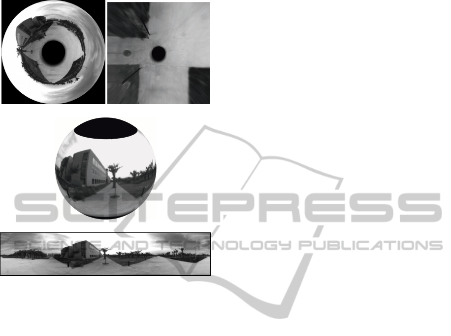
(a) Omnidirectional image (b) Orthographic view
(c) Unit Sphere projection
(d) Panoramic view
Figure 3: Different projections of the same image.
image frame, and some other pixels might not have
associated any value. We interpolate the values of the
pixels that do not have any association.
The altitude difference using this technique is rep-
resented by the displacement scale factor ρ.
After obtaining the new coordinates of the image,
we need to gather the visual information using a de-
scriptor. Note that from M
′
, we can obtain differ-
ent representations of the visual information. Specif-
ically, we use three different representations of the
scene: the orthographic view of the omnidirectional
image, the panoramic image, and the unit sphere. In
Fig. 3, an example of each projection is shown.
We use the Fourier Signature and the 2D Fourier
Transform to describe the orthographic and the
panoramic views, whereas the Spherical Fourier
Transform describes the unit sphere projection.
4 EXPERIMENTAL DATABASE
In order to carry out the experiments, we have ac-
quired our own database of omnidirectional images
in outdoor locations. We use a catadioptric system
composed of a hyperbolic mirror and a camera with a
resolution of 1280x960 pixels. The camera has been
coupled to a tripod that allow us to have a range of
165cm in altitude.
The image acquisition has been done in 10 dif-
ferent locations. From every position, we capture 12
images in different altitudes. The minimum height
is 125cm (h=1), and the maximum is 290cm (h=12),
with a step of 15cm between consecutive images. In
Fig. 2 we include some examples of database images
varying h.
Therefore, the database is composed of 120 im-
ages captured in real lighting conditions. We do not
vary the orientation of the images captured in a same
location, although small rotations regarding the floor
plane have been unavoidable.
In the database, we include images near and far
from buildings, garden areas and a parking. We also
vary the time when the images are captured to vary the
illumination conditions and to have a more complete
database.
In the experiments, we use different representa-
tions of the original visual information. Specifically,
we compute the panoramic image, the orthographic
view (or bird-eye view) and the projection onto the
unit sphere. Fig. 3 includes an example of each rep-
resentation.
5 EXPERIMENTS AND RESULTS
We test the altitude estimation methods included in
Section 3 using two different experiments.
In the first experiment, we estimate the altitude of
the images taking as a reference the scene in the low-
est altitude (h = 1) for each location. The information
that contains the database depends on the technique
and global appearance descriptor used. The combi-
nation of the altitude estimation techniques with the
different global appearance descriptors create 10 dif-
ferent possibilities.
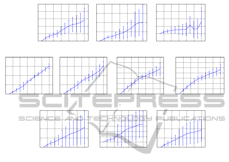
In Fig.4 we include the mean value and standard
deviation of the different altitude indicator tested in
the different locations using h = 1 as a reference.
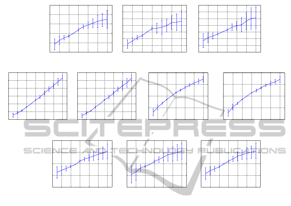
The second experiment is analogous to the first
one, but we change the reference image. In this case,
we choose the image corresponding to h = 5 (185
cm) as a reference, having test images both below
and above the comparison image. Fig. 5 includes the
mean value and standard deviation of the results for
the 10 different locations.
Taking into account all the experimental results,
we can confirm that the different methods present a
monotonically increasing tendency as we increment
the altitude lag between the compared images, with
the exception of the Vertical 2D FFT Phase, and the
VISAPP2014-InternationalConferenceonComputerVisionTheoryandApplications
198
2 4 6 8 10 12
0
5
10
15
20
25
Central Cell Correlation + Fourier Sig.
Image h
Pixels
(a)
2 4 6 8 10 12
0
5
10
15
20
Central Cell Correlation + FFT 2D
Image h
Pixels
(b)
2 4 6 8 10 12
−20
0
20
40
60
80
Vertical 2D FFT Phase
Image h
(º)
(c)
2 4 6 8 10 12
0
2
4
6
8
Zoom + Orthographic view + Fourier Sig.
Image h
∆ fc
(d)
2 4 6 8 10 12
0
2
4
6
8
Zoom + Orthographic view + FFT 2D
Image h
∆ fc
(e)
2 4 6 8 10 12
0
0.05
0.1
0.15
0.2
0.25
0.3
0.35
Cam CRS Mov+Orthographic view + Fourier Sig.
Image h
ρ
(f)
2 4 6 8 10 12
0
0.05
0.1
0.15
0.2
0.25
0.3
0.35
Cam CRS Mov+Orthographic view + FFT 2D
Image h
ρ
(g)
2 4 6 8 10 12
0
0.05
0.1
0.15
0.2
Cam CRS Mov+Panoramic + Fourier Sig.
Image h
ρ
(h)
2 4 6 8 10 12
−0.05
0
0.05
0.1
0.15
0.2
0.25
0.3
Cam CRS Mov+Panoramic + FFT 2D
Image h
ρ
(i)
2 4 6 8 10 12
0
0.05
0.1
0.15
0.2
Cam CRS Mov+Spherical Fourier Transform
Image h
ρ
(j)
Figure 4: Experimental results estimating the altitude regarding the image with h = 0. Mean and standard deviation of all the
different locations using the different methods.
Central Cell Correlation using FFT 2D for vertical
lags greater than h = 8 (230 cm).
As a rule, the standard deviation increases as the
test image distances from the reference, showing that
the descriptors are less reliable. The experiments that
use the orthographic view (independently of whether
they use zooming or camera CRS movement), present
a better accuracy in higher distances. On the other
hand, the techniques using the panoramic view show
the worst accuracy.
Considering the results of the second experiment
included in Fig. 5, when the test images are below
the reference, all the altitude indicators have negative
sign. This allow us to determine the direction of the
vertical movement. However, the Vertical 2D FFT
Phase might present negative values despite having
positive vertical displacements (Fig. 4(c)).
When we simulate the CRS movement described
in Eq.(9), we are applying the same displacement in
all the pixels of the image, independently of the dis-
tance of the object depicted in the scene. However,
when we change the altitude of the camera in the real
world, the objects included vary their position in the
image depending on their relative position with the vi-
sion system. As an instance, the projection of objects
that are far away from the camera suffers less changes
than the projection of closer objects when we vary the
sensor location.
This is particularly notable when we work with
the panoramic view or the unit sphere projection, as
we use almost the whole image, that usually includes
information of objects placed in different distances
from the camera system. On the contrary, the ortho-
graphic view usually include elements that are at a
similar distance (near the floor plane). Despite this
fact, the performance of all the algorithms that use the
CRS camera displacement are acceptable until a alti-
tude lag of 45cm (∆h = 3), although the orthographic
view outperforms the panoramic and unit sphere pro-
jection.
Regarding the descriptor used to represent the im-
age, the Fourier Signature presents better accuracy
than Fourier 2D, being this difference specially re-
markable in the Central Cell Correlation algorithm
TowardsRelativeAltitudeEstimationinTopologicalNavigationTasksusingtheGlobalAppearanceofVisualInformation
199
2 4 6 8 10 12
−10
−5
0
5
10
15
Central Cell Correlation + Fourier Sig.
Image h
Pixels
(a)
2 4 6 8 10 12
−6
−4
−2
0
2
4
6
8
Central Cell Correlation + FFT 2D
Image h
Pixels
(b)
2 4 6 8 10 12
−30
−20
−10
0
10
20
30
40
Vertical 2D FFT Phase
Image h
(º)
(c)
2 4 6 8 10 12
−2
−1
0
1
2
3
4
Zoom + Orthographic view + Fourier Sig.
Image h
∆ fc
(d)
2 4 6 8 10 12
−2
−1
0
1
2
3
4
Zoom + Orthographic view + FFT 2D
Image h
∆ fc
(e)
2 4 6 8 10 12
−0.2
−0.1
0
0.1
0.2
Cam CRS Mov+Orthographic view + Fourier Sig.
Image h
ρ
(f)
2 4 6 8 10 12
−0.2
−0.1
0
0.1
0.2
Cam CRS Mov+Orthographic view + FFT 2D
Image h
ρ
(g)
2 4 6 8 10 12
−0.1
−0.05
0
0.05
0.1
Cam CRS Mov+Panoramic + Fourier Sig.
Image h
ρ
(h)
2 4 6 8 10 12
−0.1
−0.05
0
0.05
0.1
Cam CRS Mov+Panoramic + FFT 2D
Image h
ρ
(i)
2 4 6 8 10 12
−0.1
−0.05
0
0.05
0.1
Cam CRS Mov+Spherical Fourier Transform
Image h
ρ
(j)
Figure 5: Experimental results estimating the altitude regarding the image with h = 5. Mean and standard deviation of all the
different locations using the different methods.
(Fig. 4(a) and Fig. 4(b)).
In the experiments, we can also realize that the
Spherical Fourier Transform over the unit sphere out-
performs the Fourier Signature and the FFT 2D over
the panoramic image. However, as stated above, the
handicapsderived of the camera CRS movementtech-
nique affect the results.
All the experiments show that the Vertical Phase
of the 2D Fourier Transform presents the lower accu-
rate results. In the experimental database (Section 4),
the images can present small rotations regarding the
floor plane. These rotations affect directly the phase
of the Transform coefficients (Eq. 3), and therefore,
affects to the Vertical Phase estimation. The other
techniques seem to deal better with these rotations.
6 CONCLUSIONS AND FUTURE
WORK
In this work we have presented a comparison of differ-
ent topological altitude estimation techniques appli-
cable in UAVs navigation tasks using omnidirectional
images. The approaches we included in this work de-
scribe the visual information using global appearance
descriptors. The experiments have been carried out
using our own database captured in a real environ-
ment under variable conditions.
The experimental results demonstrate that all
methods proposed are able to estimate the relative al-
titude between two scenes captured in the same loca-
tion for small altitude lags.
The techniques based on the orthographic view of
the scene present a better accuracy, specially when we
use the Camera CRS movement algorithm. However,
the same technique over the panoramic view and the
unit sphere projection presents not a reliable altitude
indicator.
Regarding the descriptors used to compress the vi-
sual information, the Fourier Signature outperforms
the 2D Fourier Transform. The Spherical Fourier
Transform is the only descriptor that would let us to
deal with 3D rotations in the space of the camera, al-
VISAPP2014-InternationalConferenceonComputerVisionTheoryandApplications
200

though combined with the camera CRS displacement
technique does not allow to obtain a good accuracy
for altitude lags greater than 185 cm.
All the methods deal with small rotations in the
floor plane, except the Vertical 2D Fourier Transform
Phase, since it is very sensitive to the change in the
phase of the Fourier Transform coefficients.
The future work should extend this research to in-
clude topological distance estimation taking into ac-
count 6D movements and topological mapping.
REFERENCES
Amor´os, F., Pay´a, L., Reinoso,
´
O., Mayol-Cuevas, W., and
Calway, A. (2013). Topological map building and
path estimation using global-appearance image de-
scriptors. In ICINCO 2013, International Conference
on Informatics in Control, Automation and Robotics.
Bay, H., Tuytelaars, T., and Gool, L. (2006). Surf: Speeded
up robust features. In Leonardis, A., Bischof, H., and
Pinz, A., editors, Computer Vision at ECCV 2006,
volume 3951 of Lecture Notes in Computer Science,
pages 404–417. Springer Berlin Heidelberg.
Bonev, B., Cazorla, M., and Escolano, F. (2007). Robot
navigation behaviors based on omnidirectional vision
and information theory. Journal of Physical Agents,
1(1):27–36.
Briggs, A. J., Detweiler, C., Mullen, P. C., and Scharstein,
D. (2004). Scale-space features in 1d omnidirectional
images. In in Omnivis 2004, the Fifth Workshop on
Omnidirectional Vision, pages 115–126.
Chang, C.-K., Siagian, C., and Itti, L. (2010). Mobile robot
vision navigation amp; localization using gist and
saliency. In Intelligent Robots and Systems (IROS),
2010 IEEE/RSJ International Conference on, pages
4147–4154.
Driscoll, J. and Healy, D. (1994). Computing fourier trans-
forms and convolutions on the 2-sphere. Advances in
Applied Mathematics, 15(2):202 – 250.
Han, K., Aeschliman, C., Park, J., Kak, A., Kwon, H.,
and Pack, D. (2012). Uav vision: Feature based
accurate ground target localization through propa-
gated initializations and interframe homographies. In
Robotics and Automation (ICRA), 2012 IEEE Interna-
tional Conference on, pages 944–950.
Huhle, B., Schairer, T., Schilling, A., and Strasser, W.
(2010). Learning to localize with gaussian process re-
gression on omnidirectional image data. In Intelligent
Robots and Systems (IROS), 2010 IEEE/RSJ Interna-
tional Conference on, pages 5208–5213.
Lowe, D. (1999). Object recognition from local scale-
invariant features. In Computer Vision, 1999. The Pro-
ceedings of the Seventh IEEE International Confer-
ence on, volume 2, pages 1150–1157 vol.2.
Makadia, A., Sorgi, L., and Daniilidis, K. (2004). Rotation
estimation from spherical images. In Pattern Recog-
nition, 2004. ICPR 2004. Proceedings of the 17th In-
ternational Conference on, volume 3, pages 590–593
Vol.3.
Maohai, L., Han, W., Lining, S., and Zesu, C. (2013). Ro-
bust omnidirectional mobile robot topological naviga-
tion system using omnidirectional vision. Engineering
Applications of Artificial Intelligence.
McEwen, J. and Wiaux, Y. (2011). A novel sampling theo-
rem on the sphere. Signal Processing, IEEE Transac-
tions on, 59(12):5876–5887.
Menegatti, E., Maeda, T., and Ishiguro, H. (2004). Image-
based memory for robot navigation using properties
of omnidirectional images. Robotics and Autonomous
Systems, 47(4):251 – 267.
Mondrag´on, I. F., Olivares-M´endez, M., Campoy, P.,
Mart´ınez, C., and Mejias, L. (2010). Unmanned aerial
vehicles uavs attitude, height, motion estimation and
control using visual systems. Autonomous Robots,
29(1), 17-34.
Pay´a, L., Fern´andez, L., Gil, A., and Reinoso, O. (2010).
Map building and monte carlo localization using
global appearance of omnidirectional images. Sen-
sors, 10(12):11468–11497.
Roebert, S., Schmits, T., and Visser, A. (2008). Creating
a bird-eye view map using an omnidirectional cam-
era. In BNAIC 2008: Proceedings of the twentieth
Belgian-Dutch Conference on Artificial Intelligence.
Scaramuzza, D., Martinelli, A., and Siegwart, R. (2006). A
flexible technique for accurate omnidirectional cam-
era calibration and structure from motion. In Com-
puter Vision Systems, 2006 ICVS ’06. IEEE Interna-
tional Conference on, page 45.
Schairer, T., Huhle, B., and Strasser, W. (2009). Increased
accuracy orientation estimation from omnidirectional
images using the spherical fourier transform. In 3DTV
Conference: The True Vision - Capture, Transmission
and Display of 3D Video, 2009, pages 1–4.
Schairer, T., Huhle, B., Vorst, P., Schilling, A., and Strasser,
W. (2011). Visual mapping with uncertainty for
correspondence-free localization using gaussian pro-
cess regression. In Intelligent Robots and Systems
(IROS), 2011 IEEE/RSJ International Conference on,
pages 4229–4235.
Valiente, D., Gil, A., Fern´andez, L., and Reinoso,
´
O. (2012).
View-based slam using omnidirectional images. In
ICINCO 2012 (2), pages 48–57.
Wang, C., Wang, T., Liang, J., Chen, Y., Zhang, Y., and
Wang, C. (2012). Monocular visual slam for small
uavs in gps-denied environments. In Robotics and
Biomimetics (ROBIO), 2012 IEEE International Con-
ference on, pages 896–901.
Winters, N., Gaspar, J., Lacey, G., and Santos-Victor, J.
(2000). Omni-directional vision for robot navigation.
In Omnidirectional Vision, 2000. Proceedings. IEEE
Workshop on, pages 21–28.
TowardsRelativeAltitudeEstimationinTopologicalNavigationTasksusingtheGlobalAppearanceofVisualInformation
201
