
Orientation and Mobility with Prosthetic Vision
Combination of Luminosity and Depth Information for Scene Representation
Guillaume Tatur
1,4
, Isabelle Marc
2,3
, Gerard Dupeyron
1,4
and Michel Dumas
3,4
1
Centre Hospitalier Universitaire de Nîmes, Place du Pr R. Debré 30000 Nimes, France
2
LGI2P, Ecole des Mines d’Alès, Parc Scientifique et Technique Georges Besse, 30035 Nimes cedex 1, France
3
Institut d’Electronique du Sud, UMR 584, 2 Place Eugène Bataillon 34095 Montpellier cedex 5, France
4
Institut ARAMAV, 12, Chemin du Belvédère, 30900 Nimes cedex, France
Keywords: Prosthetic Vision, Mobility, Depth-based Representation.
Abstract: Recent advances in visual prostheses raise good hope for enhancement of late blind people performances in
daily life tasks. Autonomy in mobility is a major factor of quality of life and ongoing researches aim to
develop new image processing for environment representation and try to evaluate mobility performances.
We present a novel approach for the generation of a scene representation devoted to mobility tasks, which
may complement current prosthetic vision research. In this work, done in collaboration with low vision
rehabilitation specialists, depth cues as well as contrast perception are made accessible through a composite
representation. After presenting advantages and drawbacks of a scene representation based solely on
captured depth or luminosity information, we introduce our method that combines both types of information
in a unique representation based on a temporal scanning of depth layers.
1 INTRODUCTION
Regaining some autonomy in mobility in unknown
environments is a critical step in improving the
quality of life for blind people, and reduces the
social handicap that they often experience. As a
consequence, numerous studies in the framework of
prosthetic vision are devoted to the issue of mobility
(Dagnelie et al., 2007; Parikh, Humayun and
Weiland, 2010; Van Rheede, Kennard and Hicks,
2010). Prostheses currently under development only
use a small number of electrodes to stimulate the
retina, and the implanted persons receive very
impoverished visual information, consisting of
patterns of a few tens of bright spots called
phosphenes. Recent clinical trials have proved that
implanted people are able to perform simple tasks
such as tracking a line on the ground, or locating
strongly contrasted objects. However, these tasks are
performed far from real life conditions and work is
still to be done in order to optimize informational
content of visual prostheses. This content is
hampered at first by the limited number of
stimulation electrodes available. But one can also
wonder about the nature of the information to be
transmitted, which is only based so far on a
grayscale representation of the environment. In
natural vision (Bruce and Green, 1990) distances are
perceived by means of different methods, some of
them using binocular cues as stereopsis and
convergence, and others based on monocular cues,
as motion parallax, occlusion, etc. This is made
possible by exploiting a set of inferences and
assumptions acquired by learning and experiencing
the structure of the world that surrounds us. This
approach is also used during training sessions for
low vision rehabilitation, when visually impaired
people are taught to use every resource possible to
understand the geometrical layout of the
environment and build a mental map of the space in
which they move (Markowitz, 2006). We therefore
assume that it is possible to change the nature of the
information transmitted by a retinal implant without
hindering its understanding by the implantee,
provided he has been taught to use this information.
For orientation and mobility tasks, we propose a new
method of representation of the scene, combining
depth and brightness information. This paper will
first discuss the advantages and limits of depth-
based representation in the case of prosthetic vision.
A method for composite representation, which
superimposes luminosity and depth data, is then
122
Tatur G., Marc I., Dupeyron G. and Dumas M..
Orientation and Mobility with Prosthetic Vision - Combination of Luminosity and Depth Information for Scene Representation.
DOI: 10.5220/0004732101220126
In Proceedings of the International Conference on Bio-inspired Systems and Signal Processing (BIOSIGNALS-2014), pages 122-126
ISBN: 978-989-758-011-6
Copyright
c
2014 SCITEPRESS (Science and Technology Publications, Lda.)

detailed, along with its expected contribution to
improvement of mobility performances.
2 PROSTETHIC VISION
SIMULATION
Figures that illustrate our words are a representation
of phosphene images, aimed at simulating prosthetic
vision. The simulated phosphene characteristics
have been derived from data gained during Argus II
project (Humayun, 2009). The phosphene image
consists of a square lattice of 9 * 9 circular light
dots. Each Gaussian shaped phosphene occupies a
31.2 minutes of arc (arcmin) field of view and
between phosphene spacing (center to center) is 36
arcmin. For information coding, N=10 gray levels
may be applied with 100% contrast (black
background).
Luminosity and depth data were
obtained from a stereo pair of cameras (STH-
MDCS3-C from VIDERE DESIGN) in rectified
geometric conditions.
3 REPRESENTATION BASED
ON LUMINOSITY DATA
Current studies devoted on mobility tasks with
prosthetic vision mainly use information gained
from grayscale images of the environment: input
image is usually split into blocks of pixels and the
average gray value of each block is used to compute
the visual characteristics of the corresponding
phosphene. For a complete review of techniques for
phosphene generation, see (Chen et al., 2009).
The ability to detect the different entities that
compose the environment, and to estimate distances
to them is of paramount importance to ensure a safe
perambulation. A luminosity-based representation
(LBR) with a few tens of phosphenes does not allow
for this spatial discrimination. A possible way to
make small objects detectable is to decrease the size
of each phosphene receptive field. However, in this
case, the entire field of view provided by the
phosphene image is dramatically reduced, and will
no longer match the minimum requirements for
mobility tasks, as estimated in (Cha, Horch and
Normann, 1992; Sommerhalder et al., 2006).
Moreover, this type of representation is strongly
influenced by the lighting conditions and may also
yield some ambiguities (for example a shadow or a
dark spot on the ground can be misinterpreted as an
obstacle), which may contribute to increase
cognitive load during mobility and orientation tasks.
4 REPRESENTATION BASED
ON DEPTH DATA
These observations lead us to propose the use of
depth information instead of luminosity (Tatur et al,
2011). In a depth-based representation (DBR), the
brightness of each phosphene is defined in relation
with the distance to the surrounding objects, its
intensity increasing as distance decreases. The
information obtained is independent of the texture
and reflectivity of entities, and of light conditions. In
the following, a method for DBR generation is
briefly described, and a comparison between the two
representations is made.
The transfer function that converts distance to
subject into intensity value for each phosphene is
established considering the maximum and minimum
distances observable: as the number of gray levels
for the representation is limited to N distinct values,
the range of distances to be rendered must also be
limited, otherwise fine spatial discrimination will not
be possible. In addition, for mobility tasks, it is
important to highlight nearby objects. For this
purpose, a nonlinear transfer function has been
defined so that it emphasizes short distances (Figure
1), which are represented by a larger number of gray
levels, and improve the contrast perception between
depth layers, to the detriment of visibility for the
more distant areas.
For and the maximum and
minimum distances, and for the highest gray level
value that can be presented on our display (255), the
gray level associated with the distance D is given by:
∗
(1)
with
255
(2)
∗
(3)
Where rnd() is the rounding function and is a
control parameter, which is empirically chosen.
Finally, a uniform quantization step allows
associating
with one of the N possible
brightness levels.
The D parameter in the previous equations stands
for a representative distance between the subject and
objects lying in the receptive field of a
given phosphene. This distance can be calculated in
OrientationandMobilitywithProstheticVision-CombinationofLuminosityandDepthInformationforScene
Representation
123
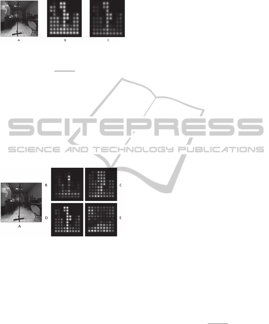
Figure 1 : DBR generation using linear and non linear
transfer function. N = 10, 6m and 0 m.
A) Full resolution image. B) DBR with linear transfer
function:
∗
and C) DBR with non
linear transfer function with =-1.7.
different ways, for example by using the arithmetic
mean of the distance values in the studied area, the
median of these values, or the minimum value.
Figure 2 shows three phosphene representations of
the same scene based on different definitions of this
D parameter. The use of median value seems to
provide better separability between the entities in the
scene, and should mitigate the influence of local
values that would result from depth value estimation
errors. It is this last definition of D which is used in
the remainder of this paper.
Figure 2: DBR generation using three distance calculation:
A : Full resolution image, B : DBR when using the mean
value of distances, C : DBR when using the minimum
value and D : DBR when using the median value. E: LBR.
A similar approach is found in (Lieby et al, 2012). In
a navigation task through a maze with overhanging
obstacles using a 30 * 30 phosphene array, depth-
based representation appears more efficient than
LBR in terms of preferred walking speed.
If the number of phosphenes is decreased in
order to concur with the current capacity of
implants, and therefore if the amount of available
information is decreased too, the DBR should be
even more interesting, as it makes it possible to
adjust the data to be transmitted. In the case of a real
environment, with many elements present in the
vicinity, it is possible to filter the information on the
basis of the distance and thus present only entities
contained in a restricted volume around the subject.
This should limit attention effort required to decode
the scene by presenting only relevant information for
a safe travel.
This type of representation also presents some
limitations. First, the number of gray levels N is
limited and it is necessary to achieve some trade-off
between resolution and range of distances to be
converted. Even more importantly, when navigating
through an unknown environment, it is of course
necessary to avoid obstacles, but it is also important
to be able to orient oneself in order to choose a
suitable (safe and non erratic) path. The luminosity
information is therefore needed to collect visual cues
as light sources as well as contrasting areas
(pedestrian crossing for instance).
We present in the next section a method to
provide the two types of information in a unified
representation.
5 COMBINING DEPTH AND
LUMINOSITY INFORMATION:
A COMPOSITE
REPRESENTATION
As the intensity A of a phosphene is the only
parameter that can be controlled in order to convey
information, transmitting two different types of
information (luminosity and depth) is not
straightforward. For this purpose, we propose a
method based on the temporal scanning of the
successive depth layers of a scene. In this
representation, the presented phosphene image
corresponds initially to the LBR, and then a
successive highlight of the objects occurs depending
of their distance to the observer until a previously set
maximum scanning distanceDmaxis reached.
For a given scanning speed S and for a maximum
distanceDmax, we define a distance p measured
from the observer at time t:
. <
(4)
For each phosphene we define a scanning related
value
∈
0 255
such as:
255∗
(5)
where σ is a parameter controlling transitional
behavior between depth layers andD, the associated
median distance.
We can then determine a composite
representation which associates for each phosphene
BIOSIGNALS2014-InternationalConferenceonBio-inspiredSystemsandSignalProcessing
124
the value A
such as:
(6)
whereA
is a threshold value directly related to the
depth layer thickness. This parameter is arbitrary
chosen to ensure the best visibility.
In order to help to distinguish between the two
different types of information, we propose to
enhance the visual contrast between them by
quantifying the LBR values on n levels while
maintaining a quantification of N levels for the
A
.
Figure 3 presents simulated prosthetic images
obtained with this composite representation.
Information for a safe navigation such as the
existence of the obstacle in the foreground of the
image is not accessible through the representation
solely based on luminosity, whereas it is possible to
detect small objects when using depth-based
representation. Scanning process is helpful too for
discrimination between objects close to each other.
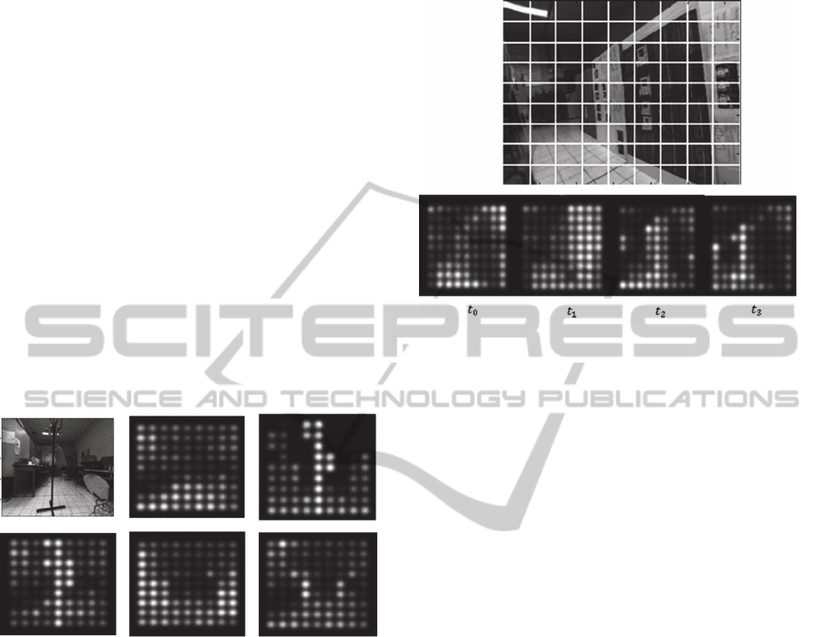
Figure 3: Composite representation: visualisation of 3
images extracted from video during scanning process. Top
raw: Full resolution (left), representation based on
luminosity data (middle), and depth based representation
(right). Bottom raw: composite representation at time t
1
<
t
2
< t
3
(from left to right).
Clues about the environment geometrical layout
might be inferred by the observer when using the
scanning technique. This phenomenon is illustrated
in figure 4, which displays a corridor-like scene. We
observe that the scanning method should lead to a
better understanding of the presented scene: depth
information indicates the presence of lateral
obstacles that border what seems to be a passage.
Moreover, the dark region on the right side of the
image which could have been interpreted as a
passage with a LBR, appears to be part of the wall
and could then be correctly interpreted as a
contrasted area of this wall. Interestingly, vanishing
points can be estimated by observing the
convergence (figure 4 from de t
tot
) of the
successive depth layers.
Figure 4: representation of a corridor-like scene. Top row:
full resolution image. Bottom row: composite
representation for the time t
tot
.
Composite representation is expected to present
other interesting characteristics. In the case of a real
environment, it is possible to filter the information
on the basis of the distance and thus present only
entities contained in a restricted volume around the
subject. This should limit attention effort required to
decode the scene by presenting only relevant
information for a safe travel. The possibility of
triggering the scanning and controlling its
parameters can be given to the implantee via a
dedicated interface. Optimal values for maximum
distance and scanning rate may be chosen in relation
with the subject walking speed or the scene content.
In this case, subject should become more efficient in
his exploration tasks, as it is known from
psychological studies that an active participation
facilitates construction of mental representations
(Wexler and Van Boxtel, 2005). Another possible
benefit of this composite representation may arise
when considering one of the shortcomming of
epiretinal prosthesis: it is conceivable that the fading
(Zrenner et al., 2010) i.e. gradual disappearance of
the sensation when a continuous stimulus is applied,
may be at least partially overcome if the scanning
technique is used, by the simple fact that it causes
the periodic update of the phosphene image.
6 CONCLUSIONS
In this paper, a method for the generation of a
OrientationandMobilitywithProstheticVision-CombinationofLuminosityandDepthInformationforScene
Representation
125

composite scene representation based on depth and
luminosity information is presented. This
representation should allow for safer mobility as
well as preserving luminosity contrast perception,
useful to orientation. Orientation and mobility tests
with well sighted subjects wearing head mounted
displays simulating prosthetic vision are underway
in order to evaluate this method and to determine
efficient values for all parameters, notably for the
scanning velocity. These tests should validate the
supposed advantages of the composite
representation. A first statement is that it is a means
to assess the presence and the position of
surrounding obstacles, independently of their
appearances and lighting condition. Scanning as
presented here can help remove possible ambiguities
between obstacles when they are in close proximity
with each other. Moreover, this method can provide
a solution to the classic dilemma between field of
view and acuity: with the scanning method,
transmitting the entire camera field of view should
be possible because thin objects can still be detected.
Finally, according to us, the major advantage of this
technique is the possibility given to the subject to
choose the scanning parameters in relation to his
current actions and expectations. Thus, visual
exploration tasks such as landmarks detection and
mental map establishment could be facilitated. The
condition to the optimal use of this new kind of
representation, particularly for the distinction
between depth and luminosity information, relies on
a complete mental assimilation of the technique
through dedicated training sessions. As a
consequence, using low vision rehabilitation
concepts, one of our future aims is to develop
pertinent learning strategies.
ACKNOWLEDGEMENTS
This research was supported by the French
Federation of the Blind and Visually Impaired
(FAF).
REFERENCES
Bruce V., Green P. (1990). Visual perception: physiology,
psychology and ecology. Lawrence Erlbaum,
Hillsdale, NJ.
Cha, K., Horch, K. W., Normann, R. A. (1992). Mobility
Performance With A Pixelized Vision System. Vision
research, 32, 1367-1372.
Chen, S. C., Suaning, G. J., Morley, J. W., Lovell N. H
(2009). Simulating prosthetic vision: I. Visual models
of phosphenes. Vision research, 49, 1493-1506
Dagnelie, G., Keane, P., Narla, V., Yang, L., Weiland, J.,
& Humayun M. (2007). Real And Virtual Mobility
Performance In Simulated Prosthetic Vision. Journal
of Neural Engineering, 4(1):92-101
Humayun MS (2009).: Preliminary results from Argus II
feasibility study: a 60 electrode epiretinal prosthesis.
Investigative ophthalmology & visual science; 50: e-
abstract 4744
Lieby P., Barnes N, McCarthy C., Liu N., Dennett H.,
Walker J.G., Botea V., Scott A.F (2012). Substituting
depth for intensity and real-time phosphene rendering:
Visual navigation under low vision conditions, ARVO
2012, Fort Lauderdale, Florida, USA.
Markowitz S.N (2006), Principles of modern low vision
rehabilitation, Canadian Journal of Ophtalmology,
vol41, pp 289-312.
Parikh, N., Humayun, M. S., Weiland J. D (2010)
Mobility Experiments With Simulated Vision and
Peripheral Cues. ARVO 2010, Fort Lauderdale,
Florida, USA.
Sommerhalder J. R., Perez Fornos A., Chanderli K.,
Colin, L., Schaer X., Mauler F., Safran A. B. and
Pelizzone, M.,(2006). Minimum requirements for
mobility in unpredictable environments. Investigative
Ophthalmology & Visual Science, vol 47.
Tatur G., Marc I., Lafon D., Dupeyron G., Bardin F.,
Dumas M. (2011) Une approche fonctionnelle en
vision prothétique : étude préliminaire dans le contexte
de la mobilité. ASSISTH'2011, Paris, France
Van Rheede J. J., Kennard C., Hicks S., (2010).
Simulating prosthetic vision: optimizing the
information content of a limited visual display.
Journal of Vision, vol 10(14):32, pp1-15.
Wexler, M., Van Boxtel, J. J. A. (2005). Depth perception
by the active observer. Trends in cognitive sciences,
9(9), 431-438.
Zrenner, E., Benav H, Bruckmann, A., Greppmaier, U.,
Kusnyerik, A., Stett, A., Stingl, K., Wilke, R.(2010).,
Electronic Implants Provide Continuous Stable
Percepts in Blind Volunteers Only if the Image
Receiver is Directly Linked to Eye Movement, ARVO
2010, Fort Lauderdale, Florida, USA.
BIOSIGNALS2014-InternationalConferenceonBio-inspiredSystemsandSignalProcessing
126
