
Towards a Systematic, Tool-Independent Methodology for Defining
the Execution Semantics of UML Profiles with fUML
J
´
er
´
emie Tatibou
¨
et, Arnaud Cuccuru, S
´
ebastien G
´
erard and Franc¸ois Terrier
CEA, LIST, Laboratory of Model Driven Engineering for Embedded Systems, P.C. 174, Gif-sur-Yvette, 91191, France
Keywords:
Execution, Semantics, fUML, Alf, Profile, Turing, DSML, MoC.
Abstract:
The purpose of UML profile mechanism is to design domain specific languages (DSL) based on UML. It
exists a wide range of UML profiles: MARTE, ROOM, SysML. Current profile design methodology only
considers the syntactic part of the language and keeps informal the execution semantics description. This
impairs Model Driven Engineering (MDE) promises which advocates for executable models. This paper
presents a systematic approach to formalize the execution semantics of UML profiles using foundational UML
(normative specification) which defines a precise semantics for a subset of UML. This approach is integrated
into the reference profile design methodology. It is illustrated on a small profile to support Turing machines.
It demonstrates capability to execute resulting profiled models through the defined semantics.
1 INTRODUCTION
The maturity of UML (OMG-UML, 2011) authoring
tools, the diversity of notations and concepts avail-
able, and the possibilities to adapt the language to
domain specific needs with profiles, are probably the
main reasons for the wide spreading of UML.
Since the beginning of its usage and adoption,
UML however suffered from a lack of formal,
machine-readable semantic description. Since 2010,
this drawback has been considerably reduced by the
release of foundational UML (OMG-fUML, 2010),
which standardizes execution semantics for a subset
of UML.
An obvious use case enabled by fUML concerns
execution of models, with the possibility for software
or system engineers to observe how their models be-
have at runtime. Engineers can thereby get reliable
evidences that their models actually perform what
they expect (Selic, 2009), with the guarantee that their
observations are not biased by tool-specific interpre-
tations. The interest of the UML community on using
such formalized semantics is confirmed by the num-
ber of tools which already provide execution support
for fUML, with both open-source (e.g., Moliz, devel-
oped by the Vienna Technical University, or Moka
1
)
or commercial (e.g., the Cameo Simulation Toolkit
for Magic Draw, or the AMUSE extension for En-
1
Developed on top of Papyrus by our laboratory at the
CEA LIST
treprise Architect) tools. However, it is important
to remind that fUML formalizes execution semantics
only for a subset of UML. Obviously, the theoreti-
cal advantage of a common, tool-independent under-
standing only holds for models complying with this
subset. As soon as non-fUML constructs are required,
tool providers have to make choices, based on their
own interpretation of UML semantics.
One fundamental issue remains on the usage of
profiles, which are the usual mechanism to adapt
UML to domain specific needs. They typically im-
ply extending or overloading the UML semantics.
While these extensions may have significant impacts
in terms of observable executions, the issue of for-
malizing execution semantics of UML profiles has
only triggered a few research proposals (Muller et al.,
2005), (Cuccuru et al., 2007), (Riccobene and Scan-
durra, 2010) and is still not standardized. This leads
profile users to obtain application models for which
they do not have a shared understanding about their
expected behaviors. In addition, since a profile has no
execution semantics, then models built with the pro-
file are not executable.
In previous works (Tatibouet et al., 2013) we pro-
posed an approach for controlling the execution of
fUML models according to specific Models of Com-
putation
2
(MoC). The approach was based on model
libraries formalizing the semantics of MoCs in the
2
Semantics of the interaction between modules or com-
ponents (Chang et al., 1997).
182
Tatibouët J., Cuccuru A., Gérard S. and Terrier F..
Towards a Systematic, Tool-Independent Methodology for Defining the Execution Semantics of UML Profiles with fUML.
DOI: 10.5220/0004696801820192
In Proceedings of the 2nd International Conference on Model-Driven Engineering and Software Development (MODELSWARD-2014), pages 182-192
ISBN: 978-989-758-007-9
Copyright
c
2014 SCITEPRESS (Science and Technology Publications, Lda.)
form of executable fUML models. In this paper, we
propose to generalize this approach, using fUML to
formalize execution semantics of UML profiles, and
thus obtain a standard compliant support to define ex-
ecution semantics of both UML and profiled UML
models.
The remainder of this paper is organized as fol-
lows. In section 2, we give a reminder on the ref-
erence methodology for the definition of UML pro-
files (Selic, 2007) and we highlight the lack of guide-
lines to specify their execution semantics and its im-
pact on current practices. In section 3, we give an
overview of the tools and methodologies that have
been developed to formalize the semantics of mod-
eling languages. We provide a comparison with our
proposal. In section 4, we rigorously apply the pro-
file design process presented in section 2. First, we
describe the definition of a language for expressing
Turing machines and its projection on UML as a set
of stereotypes and constraints. Second, we explain
our main contribution which consists in showing how
the semantics are defined with fUML and attached to
stereotyped model elements. To demonstrate the fea-
sibility of our approach, we show the execution of a
Turing machine modeled using this profile. In section
5, we conclude this article with a discussion about rel-
evant future works.
2 PROFILE DESIGN PROCESS
The UML specification describes the profile mech-
anism as a capability to extend metaclasses, in or-
der to adapt them for different domains or platforms.
The underlying motivation is to provide people using
MDE in their everyday work with a mean to develop
specialized versions of UML, tailored to their spe-
cific needs. By tuning UML they get benefit from the
wide range of modeling constructs and available tool-
ing. This general modeling framework allows them to
develop quickly a modeling language specialized for
their needs.
Designing a profile is a rigorous process whose
guidelines are established in (Selic, 2007). Section
2.1 presents this methodology as well as the criteria
defined in (Pardillo, 2010) to assess the quality of pro-
files. In section 2.2, we show that the current material
only provides guidelines about the syntactic dimen-
sion of the profile and its static semantics. Execution
semantics are neglected. We explain why this is a real
issue, and we identify the requirements of a system-
atic approach for specifying the execution semantics
of a profile.
2.1 Context and Methodology
Over the last decade a large number of profiles were
released in the MDE field. An impartial study (Par-
dillo, 2010) evaluated a subset of 39 profiles presented
in the two top levels conferences of the domain and
assessed them according to the following criteria:
A. Presence of a domain model (metamodel)
B. Constraints limiting the expressiveness of stereo-
typed UML elements
C. Presence of diagrams showing the extended meta-
classes and their stereotypes.
D. Presence of a formalized execution semantics
The results obtained showed an important hetero-
geneity in terms of quality between the evaluated pro-
files (i.e., no domain model, no constraints on the ex-
tended metaclasses, difficulties to align the domain
concepts on the profile). This can be explained by
the various levels of UML skills of profile designers,
but the main reason is probably the lack of material
providing guidelines for the construction of profiles.
As far as we know, only one methodology has been
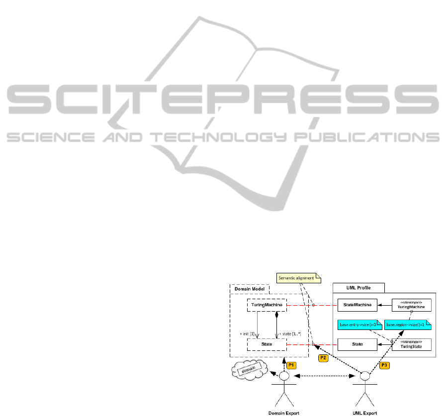
published (Selic, 2007). As illustrated in Figure 1, it
goes over three steps and can be coupled with quality
criteria previously presented. The first step is the def-
inition of the domain concepts (P1 on Figure 1, Cri-
terion A). The second one is the projection of these
latter on UML as a set of stereotypes (P2 on Figure
1, Criterion C), and the last one consists in limiting
UML expressiveness to the domain (P3 on Figure 1,
Criterion B).
Figure 1: Profile design process overview.
In the next section, we present this methodology
with an academic but representative example: a lan-
guage for expressing Turing machines. It will be used
as a case study all along the article. Basics about Tur-
ing machines are presented in section 4.1.
TowardsaSystematic,Tool-IndependentMethodologyforDefiningtheExecutionSemanticsofUMLProfileswithfUML
183

2.1.1 Definition of a Domain Model
A usual way to capture and formalize concepts of a
domain is to design a metamodel (denoted as P1 in
Figure 1) without any consideration to what the pro-
file should provide. This step is achieved by an expert
of the domain. It enables the definition of the abstract
syntax and the terminology of the modeling language.
An excerpt of the Turing Machine domain model is
depicted in the left-hand side of Figure 1.
2.1.2 Projection of Domain Concepts on UML
This step, denoted as P2 in Figure 1, consists in se-
lecting UML metaclasses that can represent concepts
provided by the domain model. A UML metaclass
is chosen if it is semantically close to a domain con-
cept. This evaluation is the result of the collabora-
tion between a domain expert and a UML expert, and
leads to the creation of specific stereotypes (e.g., Tur-
ingState in Figure 1) representing the domain concept
(e.g., State in the domain model). Although this step
is mostly manual, it can be computer assisted as ex-
plained in (Noyrit et al., 2013).
2.1.3 Limiting UML to the Domain
The UML constructs involved in a profile usually
need to be constrained to respect the expressiveness
of the domain. For example, the UML metaclass State
can be associated with an entry Behavior. In the exe-
cution semantics of UML StateMachine, this Behav-
ior shall be executed when entering a State. In our
example, the domain concept State (left-hand side of
Figure 1) is mapped onto the metaclass State (right-
hand side of Figure 1) with stereotype TuringState.
However, it has slightly different execution semantics,
since leaving or entering a State in a Turing machine
has no effect. This requires OCL (OMG - OCL, 2012)
constraints to be added (P3 in Figure 1) within the
profile to ensure the designer always produces syntac-
tically valid models (in this case, a TuringState shall
not have an entry behavior: base.entry→size()=0).
2.2 Semantics and Execution
This section highlights the lack of guidelines for spec-
ifying profile semantics and the consequences on cur-
rent practices. Then, it explains the significance of
formalizing profiles execution semantics and the di-
rect benefits of such practise.
2.2.1 Profiles and Semantics
Foundations on providing a language with its seman-
tics (i.e., meaning) are given in (Harel and Rumpe,
2004). The process consists in mapping the syntax
of a language L to its semantic domain S (M:L→S).
This mapping step enables designers to have a shared
understanding on how models built from a language
have to be interpreted.
In section 2.1, we detailed the methodology pro-
posed by B. Selic to design a profile. One can notice
it only considers the definition of the abstract syn-
tax (i.e., L) although the author makes suggestions on
how the semantic domain could be defined (i.e., using
fUML). A consequence of this lack of guidelines is
that 80% (Pardillo, 2010) of them (i.e., profiles) only
provide an abstract syntax and its associated surface
notation. This is not sufficient to allow profile users
to share a common understanding of the meaning of
the language.
2.2.2 Profiles and Execution Semantics
According to (Harel and Rumpe, 2004), providing a
language with its semantics does not mean it is exe-
cutable. We perfectly agree on that point. However,
in a large number of cases, langages and especially
modeling languages are intended to be executable.
Providing a language with an execution semantics
means this latter is depicted as an interpreter or a pro-
gram describing all valid executions for the construc-
tions available in the language. Since the language is
executable, it enables to:
+ Observe the future system at runtime as soon as
possible in the development cycle for the purpose
of detecting unexpected behaviors. This offers a
good alternative to formal techniques that usually
have scalability problems to assess large models.
+ Make models capable of collaborating at runtime
with other models that may embed different exe-
cution semantics and different representations of
time (e.g., an fUML model collaborating with a
Simulink model).
+ Enable an easier communication between stake-
holders by animating the model at runtime.
Enabling these use cases, requires profile design-
ers to provide profiles with a formalized execution se-
mantics.
Now the question is: do we have to design the ex-
ecution semantics for the domain model or for the
profile ? Pragmatically, the semantics is known by
the domain expert. Therefore, we believe it should be
designed for the domain model but must be applicable
to the profile.
A second question is: what are the requirements
that a systematic approach for specifying the exe-
cution semantics of a profile must fulfill ? We iden-
tify four main requirements:
MODELSWARD2014-InternationalConferenceonModel-DrivenEngineeringandSoftwareDevelopment
184

1. Make the specification as independent as possible
from tooling: the execution semantics must rely
on a formalism which is open and standard in or-
der to promote cross-tooling compatibility.
2. Avoid exogeneous non-conservative transforma-
tions (i.e., transformation which takes a model de-
scribed in a language with no precise semantics
and produces a representation of that model in a
language having one. However nothing says both
models have the same meaning) between model-
ing formalisms: providing reliable feedbacks on
an applicative model and avoiding loss of seman-
tics implies minimizing the number of transfor-
mation steps to associate a modeling formalism
with its execution semantics.
3. Make the specification easily accessible to design-
ers of application models: enabling them to share
a common understanding about how their profiled
models should behave at runtime requires an ex-
plicit model of the semantics.
4. Be as independent as possible from the UML pro-
jection details required by the profile definition
under consideration: the semantics of the lan-
guage relates to the domain, not to its implemen-
tation in UML.
These requirements will be used in section 3 to as-
sess state-of-the-art methodologies proposed for spec-
ifying UML profiles execution semantics.
3 RELATED WORKS
This section presents strategies and methods used to
specify execution semantics of Domain Specific Mod-
eling Languages (DSML). Then, it focuses on the ap-
proaches recently proposed to specify execution se-
mantics of UML profiles. These approaches are dis-
cussed to highlight their limits and to position our ap-
proach.
3.1 Approaches for Specifying DSMLs
Execution Semantics
A DSML is defined by a metamodel specified with
a metamodeling language. The most widespread
metamodeling language is the Meta Object Facility
(OMG-MOF, 2011), which, for example, has been
used for the definition of UML. However the scope
of MOF is limited to the structural description of a
language. No behavior can be associated with a meta-
model. Two similar approaches have been developed
to overcome this limitation.
The first one is Kermeta (Muller et al., 2005). It
consists in composing the Essential MOF (EMOF)
metamodel with an action metamodel weaving the be-
havioral aspects into the structure. The result is an
executable EMOF metamodel.
The second one is xMOF (Mayerhofer et al.,
2012). As Kermeta does, this approach proposes to
enable the definition of behavioral concerns of a lan-
guage at the metamodel level. To do so it integrates
a subset of fUML as a way to specify behavioral se-
mantics at the MOF level. The main difference be-
tween these two approaches is related to fUML: the
Kermeta language does not allow expressing concur-
rency while fUML does.
These two approaches both rely on MOF. How-
ever this is not always the case. MetaEdit (MetaCase,
2012) rather provides an ad-hoc metamodeling frame-
work enabling experts of a specific domain to design
their own modeling language. In addition, unlike Ker-
meta and xMOF, execution semantics are not explic-
itly specified; they are hidden in the code generator
associated with the newly created language.
Although these approaches are interesting, they go
beyond the UML scope and do not consider the spec-
ification of UML profiles execution semantics which
is the core purpose of this paper. In addition, Kermeta
approach is specific to the tooling and MetaCase re-
lies on a non-standard formalisms.
3.2 Approaches for Specifying
Execution Semantics of UML
Profiles
Considering statistics provided in (Pardillo, 2010),
only 20% of the state-of-the-art profiles are released
with a description of their execution semantics. When
available, this description is most of the time infor-
mal, specified in natural language. However, we also
observe three other cases:
1. As for DSMLs, the execution semantics of a
profile can be encapsulated in a code genera-
tor. For instance, in (Mraidha et al., 2008), a
framework is proposed for supporting execution
of models stereotyped with concepts issued from
the MARTE profile (OMG-Marte, 2011). These
application models are transformed into equiva-
lent C++ code encapsulating the semantics. The
generated code is executed and constrained by the
resources defined at the model level for the Ac-
cord—UMLvirtual machine (Phan et al., 2004).
2. Other approaches rely on model transforma-
tions. These latter consist in targeting a model-
ing formalism having a precise execution seman-
tics, and then to implement transformation rules
TowardsaSystematic,Tool-IndependentMethodologyforDefiningtheExecutionSemanticsofUMLProfileswithfUML
185

from the profile definition to the target formalism.
Among approaches relying on this strategy, we
can cite (Riccobene and Scandurra, 2010). This
work proposes to specify the execution seman-
tics of a subset of the SystemC profile (which is
defined by the same authors) concerning process
state machines. To do so, the UML abstract syn-
tax for state machines (and extensions established
with SystemC stereotypes) is mapped to the Ab-
stract State Machine formalism (ASM), which is
formally defined. At this step, execution seman-
tics are provided as ASM transition rules using a
textual surface notation. Therefore UML applica-
tions models annotated with the SystemC profile
are then transformed into equivalent ASM mod-
els on which the execution semantics previously
defined apply.
3. The third kind of approach consists in construct-
ing a model of the semantics of a language, usu-
ally in the form on an interpreter for that language.
In the UML context, few papers go in that di-
rection for specifying execution semantics of pro-
files. (Cuccuru et al., 2007), demonstrates how
profiling practices can be enhanced this way, with
a focus on semantics variation points introduced
by UML. It proposes a mechanism to encapsu-
late the operational semantics of semantic varia-
tion points with an execution model embedding a
behavioral description specified in fUML.
Discussion on Previous Approaches
The first approach presented in this section requires
code generation from a model to obtain an executable
form. This strategy hides the execution semantics in-
side the code generator. This does not promote an
easy access to the execution semantics and contradicts
the requirement 3 presented in section 2.2.2. Indeed,
the only way to check out computations associated to
a modeling construct is to investigate the correspond-
ing source code.
The second approach presented is based on con-
servative model transformations to obtain an exe-
cutable model. Although preservation of semantics
might be ensured, the transformation step implies that
the model actually executed is not the one produced
by the designer. It could therefore be difficult to pro-
vide feedbacks about the execution of the original
model (requirement 2 presented in section 2.2.2).
With respect to our requirements, the third ap-
proach seems the most interesting. By choosing
fUML, it makes the specification independent from
tooling (requirement 1), promotes its accessibility
(requirement 2) and avoid additional transformation
steps to provide variation points with their execu-
tion semantics (requirement 3). However, the solu-
tion proposed by this article (Cuccuru et al., 2007) is
ad-hoc to the profile and thus contradicts the require-
ment 4 presented in section 2.2.2. In addition, it was
proposed before fUML was released and can no more
be applied due to its dependency on UML templates
which are not included in the fUML final specifica-
tion.
3.3 Position of our Approach
fUML provides a formalized semantics for a
carefully-selected subset of the UML. This basic can
be viewed as a programming language and can there-
fore be used to specify semantics of other languages.
In (Tatibouet et al., 2013), we showed it was fea-
sible to formalize the execution semantics of a MoC
(i.e., semantics of interactions) using fUML and to in-
ject this latter in the runtime of an application model
to enable observation of different execution orders
and discrete time representation.
In this paper, we propose to extend this approach
and B. Selic methodology in order to specify pro-
files execution semantics. The idea is to provide a
domain model and to design its execution semantics
as a fUML model. Since the domain model and the
profile are semantically aligned then the execution se-
mantics can be applied on both. We will obtain an ex-
ecution semantics playing the role of an interpreter for
a model conforming to the DSML defined as a profile.
This execution semantics will be itself interpreted by
the original semantics provided by fUML.
By specifying the execution semantics as a fUML
model, we make it compatible with any tool imple-
menting fUML and UML (i.e., Magic Draw, Papyrus,
Entreprise Architect, Moliz, AMUSE, etc). Therefore
we promote its accessibility and we rely on an open
standard formalism. These two points fulfill the re-
quirements 1 and 3 presented in section 2.2.2.
Since we propose to design the profile and its exe-
cution semantics using the same modeling formalism,
then there is not any exogeneous model transforma-
tion required to map the language with its execution
semantics. This makes our approach compliant with
the requirement 2 presented in section 2.2.2 .
The way we design the semantics is independent
from the projection details existing between the do-
main model and the profile. Indeed the semantics
is defined according to the domain model without
any consideration to UML metaclasses that have been
chosen to be extended. This fulfills the requirement 4
presented in section 2.2.2.
MODELSWARD2014-InternationalConferenceonModel-DrivenEngineeringandSoftwareDevelopment
186
4 CASE STUDY: A DSML FOR
TURING MACHINE
In this section, we start by defining a domain model
for Turing machines. Then, we present the projec-
tion of underlying concepts and their semantic align-
ment on UML using the profile mechanism. Section
4.3 details the specification of the execution seman-
tics of Turing machines (chosen due to their closeness
to UML state machines) as a fUML model, and how
we proceed to attach these semantics with stereotyped
elements. Finally, section 4.4 illustrates the proposal
with the execution of a Turing machine specifying the
copy of a string located at a certain position of a tape,
highlighting the technical issues that were solved.
4.1 A Metamodel for Turing Machines
According to the methodology we went through in
section 2.1 the construction of a profile begins with
the construction of a metamodel capturing exclusively
the concepts of a domain without any consideration
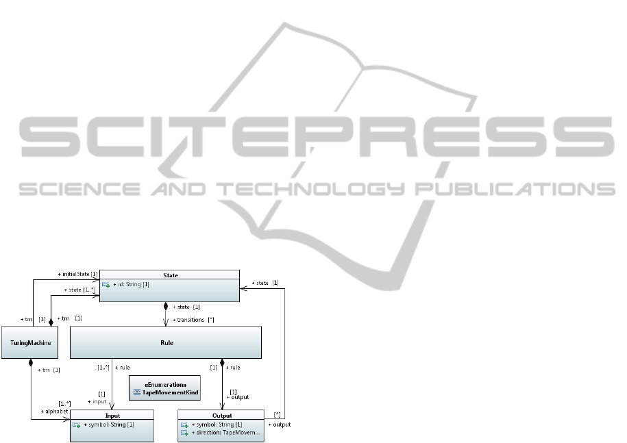
for the future UML mapping. Figure 2 is the meta-
model we defined for expressing Turing machines ac-
cording to the domain.
Figure 2: Metamodel for Turing machines.
• A TuringMachine represents a program that can
understand a specific set of inputs called alphabet.
It must be expressed as a set of States. One among
them is designated to be the initial state.
• A State represents a possible state during the ex-
ecution of a Turing Machine. It contains a set
of Rules describing state transitions, according to
symbols read on the tape.
• A Rule references an Input describing the ex-
pected symbol to be activated. It also contains an
Output which describes a set of actions that need
to be realized when activated.
• Input represents a symbol modeled as a string.
• Output represents a set of actions that needs to be
realized. The property symbol specifies a string
to be written on the tape. The property direction
specifies the direction to follow in order to move
the cursor positioned on the tape. Output also ref-
erences a target State which will be reached after
execution of the owning rule.
• TapeMovementKind element represents the differ-
ent direction that can be specified by a designer
for an Output element.
4.2 A UML Profile for Turing Machines
The second step of the methodology consists in the
projection on UML of the domain concepts proposed
in the metamodel. The difficulty is to choose the right
metaclasses in the UML metamodel in order to se-
mantically align the created stereotypes to the domain
concepts. Figure 3 presents the structure of the pro-
file.
The UML specification describes a StateMachine
as “a graph of state nodes interconnected by one or
more joined transition arcs”. Conceptually, it is close
to the TuringMachine concept. A UML StateMa-
chine describes a behavior whose dynamics is based
on event consumption. Consumption of an event is
only possible when the StateMachine is in a stable
state and occurs according to the Run To Completion
semantics. The event that is dispatched provokes a
state to be exited, a transition to fire and the target
state to be entered.
Turing machines have similar semantics. In their
context, a symbol is read on a tape which makes a
rule of the current state to be activated. The execu-
tion of the rule will modify the tape and might change
the current state. Both concepts seem to be close con-
ceptually and semantically. Therefore it seems natu-
ral to express a TuringMachine through the concept
of StateMachine. The result is the Stereotype Turing-
Machine which extends the StateMachine metaclass.
In order to limit the modeling capabilities of the orig-
inal metaclass, we add OCL constraints (an excerpt
is shown on Figure 3). For instance, a StateMachine
stereotyped TuringMachine can only have one region
since there is no concurrency.
The same process is repeated for the different con-
cepts provided in the domain model. State of Turing
machine metamodel becomes active when it is entered
as a result of the execution of a Rule and becomes in-
active when it is exited as a result of the execution of
a Rule. This is close to the semantics attached to the
UML metaclass State. Therefore we define a stereo-
type TuringState which extends that metaclass.
A UML Transition is a directed relationship be-
TowardsaSystematic,Tool-IndependentMethodologyforDefiningtheExecutionSemanticsofUMLProfileswithfUML
187
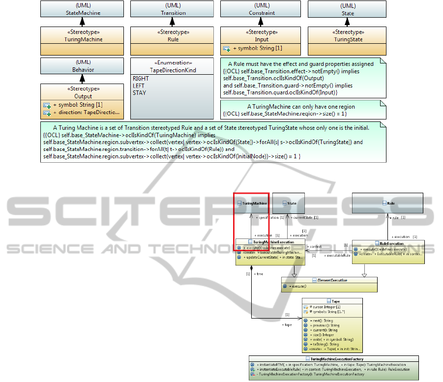
Figure 3: Profile for Turing machines.
tween a source state and a target state. A transition
can have a guard specified as a Constraint and an
effect specified as a Behavior. This latter describes
the computations to be realized whether this transition
fires. An equivalent semantics is described for Turing
machines. In the domain model we have the concept
of Rule. A Rule is owned by a State and can only be
activated if the symbol read on the tape matches the
specified Input. At this step it seems natural to map
the Rule domain concept on the metaclass Transition
and to have the stereotype Rule extending that meta-
class. The condition specified for a Rule is depicted
by an Input. This input plays the same role than the
guard specified by UML transitions. A guard is speci-
fied as a Constraint. Therefore it is cohesive to have a
stereotype Input extending the metaclass Constraint.
This will allow the guard specified on an application
model to have the stereotype Input applied. Turing
machine Rule specifies Output which describes ac-
tions that need to be performed (i.e., move on the
tape, write on the tape and go to another state) when
a rule is executed. This perfectly matches the role of
effect specified for a UML transition as a behavior.
Therefore we decided to extend the metaclass Behav-
ior with the stereotype Output.
4.3 An Execution Semantics Written in
foundational UML
After having established the stereotypes and the
semantics alignment with the domain concepts,
comes the definition of the execution semantics.
A Turing machine consumes symbols placed on a
Tape. Reading the current symbol implies executing
a Rule of the current State. The execution of a Rule
consists first in the comparison between the read input
(i.e., the symbol) and the one attached to the Rule. If
Figure 4: Semantic specification for Turing Machines.
this condition is satisfied the actions specified by the
Output of the Rule are executed. This implies:
1. Writing a symbol at the current position of the
Tape.
2. If a direction is specified moving the Tape cursor
one step forward or one step backward.
3. Switching the current state to the target State of
the Rule.
The execution semantics is specified for the Tur-
ing Machine metamodel. It is depicted in Figure 4,
as a fUML model (yellow elements) separated from
the definition of the language being capable of inter-
preting Turing machines. In this semantic specifica-
tion we have the class TuringMachineExecution. This
latter acts as a semantic visitor for a Turing machine
(i.e., specification) and describes in the definition of
its execute operation how should the Turing machine
MODELSWARD2014-InternationalConferenceonModel-DrivenEngineeringandSoftwareDevelopment
188
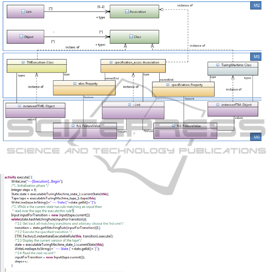
Figure 5: Semantics and application model representation at runtime.
be executed.
Figure 6: Behavior specification for TuringMachine seman-
tic visitor.
This description is formalized by an fUML activ-
ity, compiled, from a specification written with Alf
(OMG-Alf, 2012). This language is the textual sur-
face notation for fUML so there is no loss of seman-
tics during the generation step. As an example, the
Alf specification of the TuringMachineExecution ex-
ecute method is depicted in Figure 6.
This way of specifying the semantics is compliant
with the design used by fUML for designing its se-
mantics (i.e., a metaclass and semantic visitor for that
metaclass).
How will things take Place at runtime? Figure 5
details the content of three levels of abstractions M2,
M1 and M0. The level M2 presents two fUML syntac-
tic elements (i.e., Association and Class) and their se-
mantic visitors. The semantic visitor for the metaclass
Class is the metaclass Object. The meaning of this
relation is that a fUML Object represents an instance
of Class. The level M1 contains the definition of the
domain model for Turing machines and its execution
semantics specification. These two cannot be at the
level M2 since they are designed as fUML models
(i.e., models of UML classes). As an example, Fig-
ure 5, represents at the level M1 the relation between
the TuringMachine class and its semantic visitor Tur-
ingMachineExecution highlighted in red in Figure 4.
In the context of fUML, the runtime (i.e., level
M0) of a model is defined as a set of extensional val-
ues stored in a locus. These values represent fUML
instances of a particular model. Therefore, to be ex-
ecuted a Turing machine specified from the domain
model needs to be represented at the fUML locus
(M0). As shown in Figure 5, we will have an in-
stance of the class TuringMachine represented as an
instance of a fUML Object (i.e instanceofTM) whose
type is that class. This object will represent part of an
application model which is a Turing machine. Such
instances have no behaviors and so will not evolve at
runtime because they offer only a structural view of
the application model and do not embed its semantics.
This means we also need to have the execution seman-
tics represented at the locus. Therefore we will have
the TuringMachineExecution class represented as an
TowardsaSystematic,Tool-IndependentMethodologyforDefiningtheExecutionSemanticsofUMLProfileswithfUML
189
instance of a fUML Object (i.e., instanceofTME) im-
plementing part of the execution semantics for mod-
els of Turing machines. In order to make the fUML
Object depicting part of the Turing machine (i.e in-
stanceofTM) executable by the fUML Object imple-
menting its execution semantics (i.e., instanceofTME)
we will need to have in the locus a instance that rep-
resents the association between those objects. fUML
provides a Link (M2) semantic element representing
an instance of an instance of the metaclass Associa-
tion. The instance of the Link will be typed by specifi-
cation assoc (M1) as shown in Figure 5 that will own
two feature values representing values association for
both ends of the instance of the Association. This way
the association end tme will be assigned to the fUML
Object representing an instance of TuringMachineEx-
ecution (i.e., instanceofTME) and the other one spec-
ification will be assigned to the fUML Object repre-
senting the model element instance of Turing machine
(i.e instanceofTM in Figure 5). In other words, we
have at M0, an instance of the semantics model for
the Turing machines which is executed through the
semantics of fUML and the execution of that model
provokes the execution of an application model de-
scribing a Turing machine according to the execution
semantics provided in the semantic model.
4.4 Execution of a State Machine tuned
to the Turing Machine Domain
Being able to execute a state machine having the pro-
file for Turing machines applied through the execu-
tion semantics defined for the domain model requires
solving two problems:
1. The Turing machine semantic model can only ex-
ecute an application model designed from the do-
main model.
2. To be represented at a specific locus an application
model must be designed with the elements that are
part of the fUML subset.
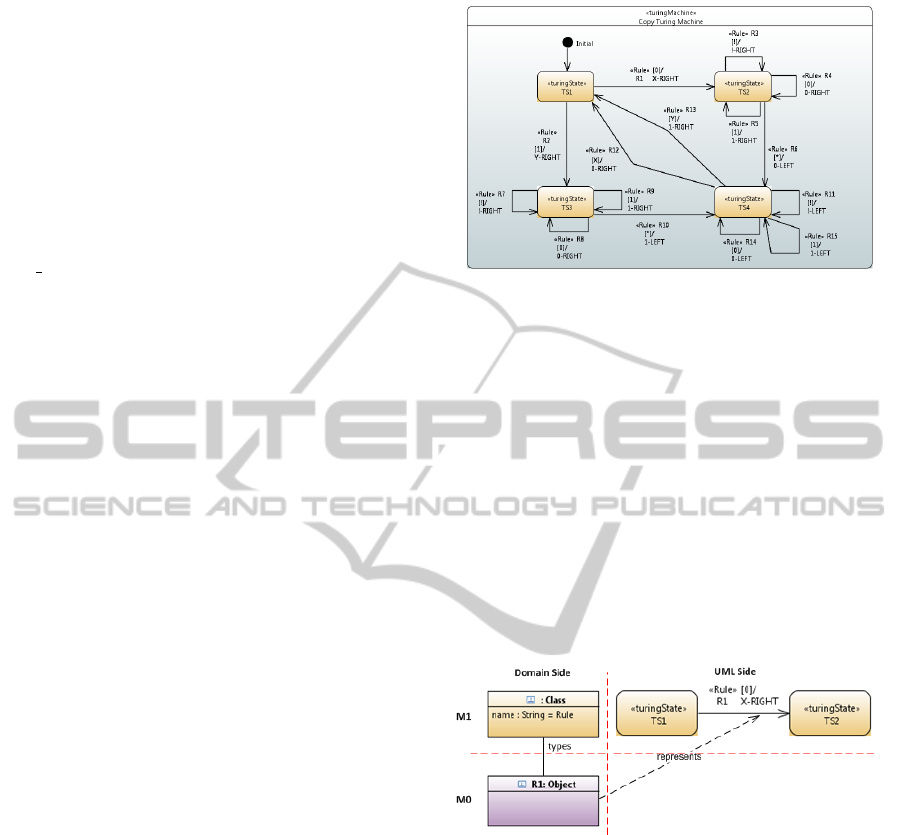
4.4.1 Case Study
In order to illustrate that section we designed a
particular instance of a Turing machine specified
as a profiled UML state machine (cf. Figure
7). This latter is capable of copying a string
located on a tape after a specific symbol. As
an example if the Turing machine works on the
tape [1—0—1—1—0—!—*—*—*—*—*—*—*]
it will copy the string “10110” after the delim-
iter “!”. The result would be the following tape
[1—0—1—1—0—!—1—0—1—1—0—*—*].
Figure 7: Specification of a copy Turing machine.
4.4.2 Solution
A profiled state machine representing a Turing ma-
chine must be viewed as a set of instances classified
under specific UML metaclasses (i.e., State, Transi-
tion, Constraint, Region). At this step, these instances
cannot be registered at a specific Locus because they
are not fUML Object instances. Therefore, the first
challenge is to be able to obtain an equivalent rep-
resentation of this application model (M1) designed
with state machines modeling constructs in fUML
(M0). To do so, we introduce a transformation step
which for every elements of the profiled state machine
specifies how to obtain an equivalent fUML Object.
Figure 8: Projection of the application model to the fUML
runtime via transformation.
In the fUML context, the metaclass Transition has
no semantics then the created fUML Object should
not be typed by that metaclass. In the other hand, we
have in the definition of the Turing machine language
the metaclass Rule which is semantically aligned on
the meaning of a UML Transition stereotyped Rule.
Therefore we inject within the fUML Locus a fUML
Object classified under domain concept Rule (cf. Fig-
ure 8). First this action gives a counterpart of our
stereotyped transition in fUML. Next it makes it in-
terpretable by the execution semantics defined for the
Turing machine language.
At this step, there is no synchronization between
the profiled model and its equivalent expressed with
fUML. In other words, this means we do not know
the matching between a stereotyped element and a
MODELSWARD2014-InternationalConferenceonModel-DrivenEngineeringandSoftwareDevelopment
190
fUML Object. The interest in the formalization of that
matching is important at two levels. From a concep-
tual point of view, it shows the semantics alignment
between a stereotyped element and its fUML equiv-
alent. This ensures we are cohesive when we give
feedback on an execution related to a stereotyped el-
ement. From a technical point of view this link can
be used to highlight the graphical representation of a
model element in a diagram. This should really help
the designer to observe and understand the execution
of its application model.
Figure 9: Link between the profiled element and its coun-
terpart within the fUML Locus.
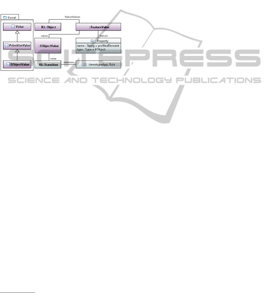
Formalization of this link between the profiled el-
ement and its fUML representation takes place while
transformation occurs. In fUML an Object represents
an instance of a class at a Locus. If that class has prop-
erties then the Object needs to be able to represent
them. This is realized thanks to the concept of Fea-
tureValue which associates a Property to its value. We
use this concept to represent the link between a stereo-
typed element and its fUML representation. As an ex-
ample, in Figure 9, R1 Object instance stands for the
representation of the stereotyped transition R1 in the
fUML context. To make the traceability link explicit
between these instances, we add a new feature value
to the fUML Object R1. This feature value either ref-
erences a property named profiledElement having the
type EObject and a value for this latter. The value is
of type EObjectValue which is a specialization of the
fUML type PrimitiveValue. It offers the possibility
of having a fUML value whose type is EObject (i.e.,
with the meaning of EMF
3
) and the pointed value is
the stereotyped transition R1. Therefore at any time
the fUML Object R1 remains synchronized with its
source stereotyped model element. This makes possi-
ble at runtime to ask information to this latter or notify
it in order to insert feedback about the execution at the
UML model level.
3
http://www.eclipse.org/modeling/emf/
ACKNOWLEDGEMENTS
We wish to acknowledge Bruno Marques, CEA LIST,
for its technical contribution in the context of this
project.
5 CONCLUSIONS, LIMITATIONS
AND FUTURE WORKS
This paper presents an approach for defining the ex-
ecutable semantics of a DSML embedded in a pro-
file as a fUML model. This approach is integrated
in the profile development process defined in (Selic,
2007). In addition, we demonstrated its feasibility
by executing profiled state-machines defining Turing
machines through the execution semantics we speci-
fied as a fUML model.
By supporting the definition of an execution se-
mantics in the profile design process we encourage
profile designers to produce technically and semanti-
cally (i.e., which does not contradict UML) valid pro-
files. The interest for the users of these profiles is
that they get executable UML profiled models. Exe-
cutability enables them to drive development of their
application models. Indeed they are able to validate
them by simulation of well-defined scenarios, assess
their design and use debugging facilities.
The format (i.e., a fUML model) chosen to embed
the semantics specification ensures it is usable by any
tools implementing the UML standards (fUML and
UML 2.5). Moreover designer can easily access it and
share a common understanding on the meaning of the
language for which the semantics applies. Providing
the execution semantics of a profile as a fUML model
ensures semantics preservation. Indeed we always are
in the context of a UML model capable of interpreting
another UML model.
A limitation of this work that can already be an-
ticipated is that the semantics is specified for profiled
elements that do not belong to the syntactical subset
considered by fUML. In our current on-going works
we evaluate how the approach presented in this paper
applies to specify the semantics of stereotyped activ-
ity nodes or edges. As an example, whether a Con-
trolFlow is stereotyped “delay”, this could imply a
different execution semantics than the one defined by
fUML. Indeed this latter could provoke the behavior
owning the seterotyped ControlFlow to wait for cer-
tain quantum of time before transmitting tokens to the
target activity node.
The second limitation relies on the mapping be-
tween the domain concepts and the profile. Instead of
having a one to one mapping we could have situations
TowardsaSystematic,Tool-IndependentMethodologyforDefiningtheExecutionSemanticsofUMLProfileswithfUML
191

where a domain concept maps to a set of UML ele-
ments and vice versa. This has an impact on the way
we keep the synchronization between the model rep-
resented at the fUML Locus and the profiled model.
We currently evaluate a solution applying the proxy
design pattern in order to deal safely with these situa-
tions.
At the present time, we are applying the approach
presented in this paper to specify the execution se-
mantics for the ROOM
4
(Selic and Limited, 1996)
profile. This profile is the projection of a modeling
language built for designing real-time and embedded
application.
REFERENCES
Chang, W.-T., Ha, S., and Lee, E. A. (1997). Heteroge-
neous simulation: Mixing discrete-event models with
dataflow. J. VLSI Signal Process. Syst., 15(1/2):127–
144.
Cuccuru, A., Mraidha, C., Terrier, F., and G
´
erard, S. (2007).
Enhancing uml extensions with operational semantics
behaviored profiles with templates. In Proceedings
of the 10th international conference on Model Driven
Engineering Languages and Systems, MODELS’07,
pages 271–285, Berlin, Heidelberg. Springer-Verlag.
Harel, D. and Rumpe, B. (2004). Meaningful model-
ing: What’s the semantics of semantics? Computer,
37(10):64–72.
Mayerhofer, T., Langer, P., and Wimmer, M. (2012). To-
wards xmof: executable dsmls based on fuml. In Pro-
ceedings of the 2012 workshop on Domain-specific
modeling, DSM ’12, pages 1–6, New York, NY, USA.
ACM.
MetaCase (2012). Domain specific modeling with
metaedit+ : 10 times faster than uml.
Mraidha, C., Tanguy, Y., Jouvray, C., Terrier, F., and
G
´
erard, S. (2008). An execution framework for marte-
based models. In Proceedings of the 13th IEEE In-
ternational Conference on on Engineering of Com-
plex Computer Systems, ICECCS ’08, pages 222–227,
Washington, DC, USA. IEEE Computer Society.
Muller, P.-A., Fleurey, F., and J
´
ez
´
equel, J.-M. (2005).
Weaving executability into object-oriented meta-
languages. In Proceedings of the 8th international
conference on Model Driven Engineering Languages
and Systems, MoDELS’05, pages 264–278, Berlin,
Heidelberg. Springer-Verlag.
Noyrit, F., G
´
erard, S., and Terrier, F. (2013). Computer
assisted integration of domain-specific modeling lan-
guages using text analysis techniques. In Proceedings
of the 16th international conference on Model Driven
Engineering Languages and Systems, MoDELS’13.
OMG-Alf (2012). Action language for foundational uml.
Technical report, Object Management Group.
4
Real-Time Object-Oriented Modeling
OMG-fUML (2010). Semantics of a foundational subset
for executable uml models. Technical report, Object
Management Group.
OMG-Marte (2011). Modeling and analysis of real-time
embedded systems. Technical report, Object Manage-
ment Group.
OMG-MOF (2011). Meta object facility. Technical report,
Object Management Group.
OMG-UML (2011). Unified modeling language. Technical
report, Object Management Group.
Pardillo, J. (2010). A systematic review on the definition
of uml profiles. In Proceedings of the 13th interna-
tional conference on Model driven engineering lan-
guages and systems: Part I, MODELS’10, pages 407–
422, Berlin, Heidelberg. Springer-Verlag.
Phan, T. H., Gerard, S., and Terrier, F. (2004). Lan-
guages for system specification. In Grimm, C., editor,
Languages for system specification, chapter Real-time
system modeling with ACCORD/UML methodology:
illustration through an automotive case study, pages
51–70. Kluwer Academic Publishers, Norwell, MA,
USA.
Riccobene, E. and Scandurra, P. (2010). An executable se-
mantics of the systemc uml profile. In Proceedings
of the Second international conference on Abstract
State Machines, Alloy, B and Z, ABZ’10, pages 75–
90, Berlin, Heidelberg. Springer-Verlag.
Selic, B. (2007). A systematic approach to domain-specific
language design using uml. In Proceedings of the
10th IEEE International Symposium on Object and
Component-Oriented Real-Time Distributed Comput-
ing, ISORC ’07, pages 2–9, Washington, DC, USA.
IEEE Computer Society.
Selic, B. (2009). Elements of model-based engineering with
uml2: What they don’t teach you about uml.
Selic, B. and Limited, O. (1996). Real-time object-oriented
modeling (room). In Proceedings of the 2nd IEEE
Real-Time Technology and Applications Symposium
(RTAS ’96), RTAS ’96, pages 214–, Washington, DC,
USA. IEEE Computer Society.
Tatibouet, J., Cuccuru, A., G
´
erard, S., and Terrier, F. (2013).
Principles for the realization of an open simulation
framework based on fuml (wip). In Proceedings of
the Symposium on Theory of Modeling & Simulation -
DEVS Integrative M&S Symposium, DEVS 13, pages
4:1–4:6, San Diego, CA, USA. Society for Computer
Simulation International.
MODELSWARD2014-InternationalConferenceonModel-DrivenEngineeringandSoftwareDevelopment
192
