
From Concrete to Abstract
About Teaching UML Class Diagrams to Novice Programmers
Jo˜ao Paulo Barros
1,2
1
Instituto Polit´ecnico de Beja, Escola Superior de Tecnologia e Gest˜ao, Beja, Portugal
2
UNINOVA CTS, Monte de Caparica, Portugal
Keywords:
UML, Class Diagrams, Object Diagrams, Introductory Programming, Abstraction, Software Engineering,
Design, CS1, Java.
Abstract:
Object-oriented programming is frequently taught in the first programming course. The implicit level of
indirection, expressed in the name-value duality of objects, demands an additional level of abstraction ability.
This brings an additional complication for novice students, which are also fighting with flow control and
composition. Graphical languages can help visualise the program structure but only if they are not seen as an
additional burden. UML class diagrams are the most widely used structure diagram for object-oriented code,
but they are very complex for novices. This paper presents a set of translation rules from code to a UML class
diagrams that can be introduced in the first or second programming course. To that end, it discusses how to
meaningfully explain the semantics of class and object relations, namely by presenting a minimal subset of
the UML class diagram metamodel that supports simple and direct translations from object-oriented code. As
most students learn better from concrete to abstract, this minimal subset and the respective code translation
provide an intermediate step towards the use of a more complete metamodel in more advanced courses.
1 INTRODUCTION
When learning object-oriented programming, UML
class diagrams (OMG, 2011) are an important subject
in itself, but they also offer a way to improve students’
abstraction capabilities, more specifically as an inter-
mediate step between programmingability and design
ability, a move from concrete to abstract. Yet, UML
class diagrams is a large and complex language with
lots of complex details. This is especially problematic
for novice students (e.g. (Wrycza and Marcinkowski,
2007)). This has motivated the creation of simpler
UML editors (e.g. (Turner et al., 2005)), which as-
sume a subset of the UML class diagrams. Here we
show how UML class diagrams can be introduced as a
translation from code, so as to simplify the transition
from a more concrete (Java
TM
code) to a more abstract
one (the class diagram). To that end, we use a mini-
mal subset of the UML class diagrams metamodel.
We do not propose yet another UML editor. In
fact, any UML editor will be adequate, as long as the
appropriate path to the used constructs is previously
shown to the students and made available, preferably
as a screen cast allowing repeated viewing. Naturally,
a simple editor will be a better option, e.g. the UMLet
editor (Auer et al., 2010).
To easy the move from concrete to abstract, the
UML class diagrams subset, which we named mini-
malCD, is defined and presented as a direct mapping
between object-oriented code, which we exemplify
using Java
TM
, and UML class diagram constructs.
This mapping is the fundamental part. A clear map-
ping between the concrete (the code) and the abstract
(the class diagram) will help students build their ab-
straction skills.
The following section briefly introduces UML
class diagrams focusing on a metamodel subset for
the specification of classes. In Section 3 we identify
the set of relationshipsin minimalCD. Next, we use an
example and code skeletons to informally present the
mappings between object-oriented code (exemplified
using Java
TM
) and the respective relationships in the
class diagram. Finally, before concluding, we briefly
discuss the importance of objects’ specification at the
diagram level and show that the view of a class dia-
gram as an abbreviation for a large object diagram is
supported by the UML specification.
278
Paulo Barros J..
From Concrete to Abstract - About Teaching UML Class Diagrams to Novice Programmers.
DOI: 10.5220/0004594302780283
In Proceedings of the 8th International Joint Conference on Software Technologies (ICSOFT-EA-2013), pages 278-283
ISBN: 978-989-8565-68-6
Copyright
c
2013 SCITEPRESS (Science and Technology Publications, Lda.)

2 UML CLASS DIAGRAMS
Object-oriented textual programs are often modeled
by graphical specification languages. The reasons
are related to the well-known fact that images help
the understanding of code, typically due to an in-
creased level of abstraction. Among graphical spec-
ification languages for object-oriented development,
UML is by far the most widely used set of languages.
These are usually divided in structure and behavior
languages (or diagrams). Class diagrams are the most
popular structure diagrams. Due to the level of de-
tail, and also due to some more complex constructs,
they are overwhelming for novices. Yet, if restricted
to the more important and commonly used parts, they
are also one of the easiest diagrams to present to stu-
dents, as they can be seen as a very direct translation
of source code. Next, we present the minimalCD set
of relations between classes in a class diagram.
2.1 The minimalCD Subset of UML
Class Diagrams
When presenting class diagrams to novices the first
thing is to be minimalistic right from the start. More
specifically, it should be stressed that class diagrams
have basically two kinds of ”pieces”: rectangles, rep-
resenting classes, and arrows, representing relations
between those classes. Then, we should proceed to
show the followingmappings between code written in
some class and the rectangle that represents that same
class:
• Class name;
• Type and name for each attribute;
• Method headers.
This mapping is quite trivial, but its simplicity
should be used to stress some important points:
• Code is a textual language and class diagrams are
a visual or graphical language;
• Class diagrams are inherently more abstract than
code, as they do not contain all the details we have
to include in code. Most notably, we are not go-
ing to include method bodies and, often, not even
method headers.
As an example of the adequate level of detail, Fig.
1 shows a Student class with several attributes and
four methods.
Attributes and method visibility can be specified
by the following syntax:
Figure 1: A class specification containing attributes (both
private) and four methods: three public and one private
Notation Visibility
+ public
- private
# protected
˜ package visibility
The following step is to introduce relations. At
this point it is important to stress a few more facts:
• Relationships between class are in fact ”relations”
between objects of those classes.
• Different relations use different lines and arrows.
Regarding arrows it is especially important to note
that different arrows have different meanings, just
like a colon is different from a semicolon in tex-
tual languages.
• The attributes responsible for the specification of
relations (namely, associations or dependencies)
should not be appear in the class specification. For
example, in Fig. 2, syllabus for objects of class
Course should not appear as an attribute, as it is
already responsible for an association.
• As a rule, only simple numerical types and strings
are represented as attributes inside each class. The
others will be specified using the graphical nota-
tion.
The first point deserves especial attention, as it is
one of the most confusing aspects in class diagrams,
but a fundamental one that should not be avoided. We
will return to this topic after presenting the recom-
mended relationships, the ones in minimalCD.
The following section presents the six relation-
ships used in minimalCD.
3 RELATIONSHIPS
We consider two sets of relationships from the UML
metamodel, each one corresponding to a complexity
level:
Minimal Set: This includes only DirectedRelation-
ships, more specifically, Generalization, Interfac-
eRealization, and Usage;
FromConcretetoAbstract-AboutTeachingUMLClassDiagramstoNoviceProgrammers
279
Complete Set: All the above, plus the Association
relationship.
The minimal set is the one used by the BlueJ tool
(K¨olling et al., 2003; K¨olling, 2013). The complete
set adds associations, which include simple associa-
tion and also shared and composite aggregation. The
two levels allow the teacher to first introduce the min-
imal set, e.g. using the BlueJ tool, and only latter to
advance to the second one (the complete set), eventu-
ally in a second course.
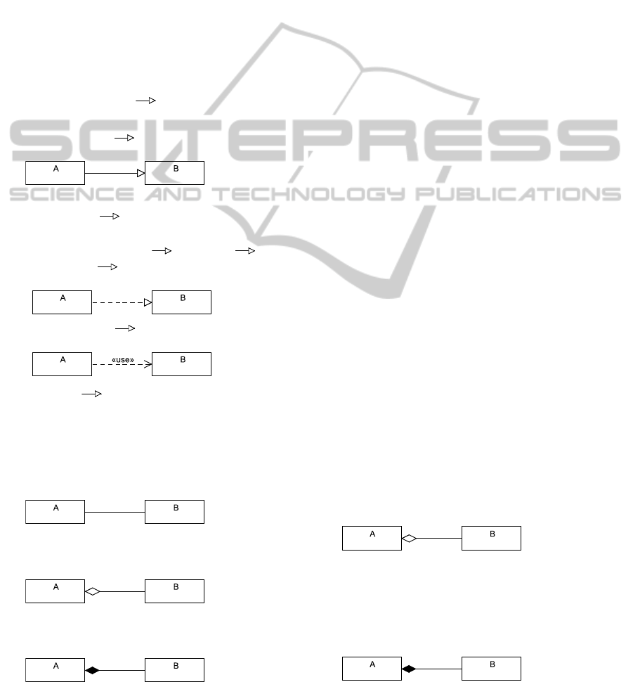
Next, we list the six Relationships in minimaCD,
contextualised by the respective metamodel, and ac-
companied by the respective graphical notation for
classes A and B (see also the example in Fig. 2):
1. Directed relationships
(DirectedRelationship
Relationship)
(a) Generalization/Inheritance:
(Generalization
DirectedRelationship) (e.g.
between LocalStudent and Student)
(b) Dependency
(Dependency DirectedRelationship)
i. Interface Realization:
(InterfaceRealization Realization
Abstraction Dependency) (e.g. between
Student and Comparable)
ii. Usage (Usage Dependency)
(e.g. between Syllabus e Validator)
2. (Association Relationship) minimalCD only
includes binary associations. Each association
end can have one of the following three values:
(a) Simple Association: (Aggrega-
tionKind=none)(e.g. between Teacher and
Course)
(b) Shared Aggregation: (Aggrega-
tionKind=shared)
(e.g. between Program and Course)
(c) Composite Aggregation:
(AggregationKind=composite)
(e.g. between Course and Syllabus)
The following section presents the respective
mapping from Java
TM
code to minimalCD models.
4 MAPPINGS
When using the minimal set presented in the previ-
ous section, all associations are modelled as generic
dependencies, just like in the BlueJ tool. Here, we
present our proposed mappings for the complete set
where we distinguish three types of association: sim-
ple, composite, and shared. These are the mappings
that should be taught to students as a first step towards
the understanding of relations in class diagrams.
4.1 Associations
An association is the most common way to compose
objects: one object has another one. It seems simple,
but it is not, and for two reasons, which correspond to
two cases:
1. An object can have or be associated to another
object without being part of it. For example, we
say that a teacher has or is associated to courses,
but those courses are not part of the teacher.
2. When we say that one object has another object,
in fact, it has the name of another object, not the
other object itself. That allows that second object
to belong to more than one object.
In the first case, where one object has another ob-
ject that it is not part of the first, we should use a
simple association.
In the second case, when we feel secure to say
that one object is part of another object, our associ-
ation is in fact an aggregation. When in doubt, we
should avoid it and use a ”simple” association, with-
out aggregation. Yet, if we decide that it is in fact an
aggregation (one object is part of another), then we
should decide between two forms:
Shared aggregation The class A object contains (the
name of) one of the class B objects, but with-
out exclusivity. Hence, other objects can contain
the name of the same class B object. As already
shown, this is specified by the addition of a small
unfilled diamond next to the composite object.
Composite aggregation In each instant, only one
class A object contains the name of the classe B
object. This is specified by a small filled rectan-
gle next to the composite object. The composite
object is responsible for the existence and storage
of the component object.
As a general rule, associations are implemented in
code (e.g. Java
TM
) putting object names inside other
ICSOFT2013-8thInternationalJointConferenceonSoftwareTechnologies
280
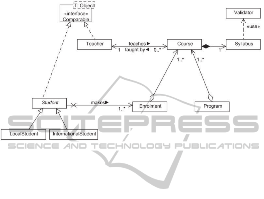
Figure 2: An example with all the minimalCD relationships.
objects. Sometimes different associations can have
the same textual specification. This happens because
the decision if one object is part of another one forces
a real world interpretation.
Next, we present Java
TM
code skeletons that ex-
emplify the textual specification of the several associ-
ations in Fig. 2.
class Teacher implements Comparable<Teacher>
{
// association:
private List<Course> courses;
...
}
abstract class Student implements
Comparable<Student>
{
// association:
private List<Enrolment> es;
...
}
class Course
{
// association:
private Teacher teacher;
// composite aggregation:
private Syllabus syllabus;
...
}
class Enrolment
{
// shared aggregation:
private List<Course> courses;
...
}
class Program
{
// shared aggregation:
private List<Course> courses;
...
}
Code skeletons like these should be used to pro-
vide the set of ”recipes” for the translation. Initially
this should be done from code to class diagrams (in-
creasing abstraction), and latter from class diagrams
to code (decreasing abstraction).
4.2 Is-a Relations
Generalization, or inheritance, and interface realiza-
tion are probably the most characteristic relations in
object-oriented development as they are the basis for
dynamic binding and polymorphism. Fortunately,
they are easily recognizable in code. For example,
Java
TM
even has specific reserved words for general-
ization/inheritance (extends) and interface realization
(implements). Sometimes it can be tricky to choose
from the three kinds of association, hence their re-
placement by a generic dependency; yet, generaliza-
FromConcretetoAbstract-AboutTeachingUMLClassDiagramstoNoviceProgrammers
281

tion and interface realization are straightforward to
identify and translate to UML.
Next, we present Java
TM
code skeletons that ex-
emplify the textual specification of the several gener-
alizations and interface realizations in Fig. 2.
class Teacher implements Comparable<Teacher>
{
private List<Course> courses;
...
}
abstract class Student
implements Comparable<Student>
{
private List<Enrolment> enrolments;
...
}
class LocalStudent extends Student
{
...
}
class InternationalStudent extends Student
{
...
}
4.3 usage
Formally, usage is a kind of dependency. Yet, this is
not very useful when teaching novices when to use it
in a class diagram, as all relations model some kind of
”dependency”, even if not the formal one. Regarding
usage, novices can use the following rule of thumb:
usage should be used when there is a compiler depen-
dency and none of the other relationships is applica-
ble. The typical cases where we have a usage relation
without association, generalization, or interface gen-
eralization are the following:
1. When the class A object uses a class B object as
a local variable, but not as an attribute. Then, A
uses B.
2. When a class A object receives a class B object as
a parameter, but does not store it as an attribute.
Then, A uses B.
Two additional concepts should also be intro-
duced: navigability and multiplicity.
4.4 Navigability and Multiplicity
For each association, the students should learn to
specify the navigability and multiplicity between ob-
jects. Regarding the former, the rule to be taught is
the following: if one object has the name of another
object as an attribute, then it can navigate to that other
object, as it knows about it. The association between
Student and Enrolment, in Fig. 2, exemplifies the two
important notations for specifying navigability: the
cross and the open arrow.
Students should also learn to specify multiplicity.
The UML allows the following possibilities, which
are simple enough to be taught to novices:
Notation Multiplicity
0..1 zero or one
1 one
0..* or just * zero or more
1..* one or more
n..* n or more (with n > 1)
n only n (with n > 1)
0..n zero to n (with n > 1)
1..n one to n (with n > 1)
n..m n to m (with n > 1, m > 1 and n < m)
The letters n and m represent natural numbers.
5 RELATIONS AND LINKS
Frequently it is useful to model objects as a way
to better grasp the program dynamic structure and
also as an intermediate step when identifying classes.
Hence, it should be made clear that the class diagram
allows an abbreviation for a large object model that
would contain all objects of all classes. This view is
supported by the UML specification as each relation-
ship can be seen as a set of ”relations” between ob-
jects. More specifically, here is what the UML speci-
fication says:
Regarding association and generalization rela-
tionships, we find the following semantics:
Association: ”An association declares that there can
be links between instances of the associated
types.” (page 37 in (OMG, 2011)).
Generalization: ”A generalization is a taxonomic
relationship between a more general classifier and
a more specific classifier. Each instance of the
specific classifier is also an indirect instance of the
general classifier.” (page 70 in (OMG, 2011)).
Hence, an association models a set of links. These
can be seen as ”relations” between the class instances
(the objects). Something similar happens with the
generalization relationship, where ”each instance of
the specific classifier” (the class) ”is also an indirect
instance of the general classifier”.
The dependency relationships that we consider,
Usage and InterfaceRealization, do not exhibit this
duality so clearly, but it is still there:
Usage: ”A usage is a relationship in which one ele-
ment requires another element (or set of elements)
ICSOFT2013-8thInternationalJointConferenceonSoftwareTechnologies
282

for its full implementation or operation. In the
metamodel, a Usage is a Dependency in which the
client requires the presence of the supplier.” (page
139 in (OMG, 2011));
InterfaceRealization: ”A classifier that implements
an interface specifies instances that are conform-
ing to the interface and to any of its ancestors.”
(page 89 in (OMG, 2011)).
Both semantics can be read at the level of in-
stances. Therefore, for all relationships that we pro-
pose, the lines between classes can be seen not only
as relationships between classes, but also as ”relation-
ships” between the respective objects. This can be
presented as a ”compact” notation: instead of mod-
eling the relationships between all objects, we model
relationships between the respective classes.
6 CONCLUSIONS
We have proposed a way to introduce UML class di-
agrams to novice programmers, more specifically we
have shown how the main relations can be related to
Java
TM
code, which students typically know. To that
end, we presented a proposal for a subset of the UML
class diagram metamodel. The mapping between a
small set of simple programming constructs and UML
classes and relationships should allow students to be-
gin applying more abstract models, hence improving
their abstraction skills while learning how to construct
models from code. The presented translations can
also provide a foundation for a more complete use of
class diagrams in more advanced courses.
ACKNOWLEDGEMENTS
This work was financed by Portuguese Agency ”FCT
- Fundac¸˜ao para a Ciˆencia e a Tecnologia” in
the framework of projects PEst-OE/EEI/UI0066/2011
and PTDC/EEI-AUT/2641/2012.
REFERENCES
Auer, M., Poelz, J., Fuernweger, A., Meyer, L.,
and Tschurtschenthaler, T. (2010). UMLet.
http://www.umlet.com/.
K¨olling, M. (2013). BlueJ – The interactive Java Environ-
ment. http://bluej.org/.
K¨olling, M., Quig, B., Patterson, A., and Rosenberg, J.
(2003). The BlueJ system and its pedagogy. Journal
of Computer Science Education, 13(4).
OMG (2011). OMG Unified Modeling Language
TM
(OMG
UML), Superstructure. version 2.4.1.
Turner, S. A., P´erez-Qui nones, M. A., and Edwards, S. H.
(2005). minimUML: A minimalist approach to UML
diagramming for early computer science education. J.
Educ. Resour. Comput., 5(4):1.
Wrycza, S. and Marcinkowski, B. (2007). A Light
Version of UML 2: Survey And Outcomes. In
Proceedings of the 2007 Computer Science and
IT Education Conference. IEEE. Available at
http://citeseerx.ist.psu.edu/viewdoc/
summary?doi=10.1.1.102.7819.
FromConcretetoAbstract-AboutTeachingUMLClassDiagramstoNoviceProgrammers
283
