Observation-based Assistance by Mobile Robot for Object Handling
of its Partner Robot
Toyomi Fujita and Tetsuya Endo
Department of Electronics and Intelligent Systems, Tohoku Institute of Technology, Sendai, Japan
Keywords:
Robot Vision, Cooperation by Observation, SIFT, Stereo Vision.
Abstract:
The authors consider a situation in which a working robot can not detect a target object to handle due to a
sensor occlusion. If another cooperative robot that has a camera observes the working robot with the target
object and detects their positions and orientations, it will be possible for the working robot to complete the
handling task. This study proposes a method for such an indirect cooperation with assistance based on an
observation by the partner robot. The observing robot obtains corresponding points of SIFT(Scale-Invariant
Feature Transformation) on the working robot with hand and the target object from multiple captured images.
The 3-D position of the target object and hand motion of the working robot can be detected by applying
stereo vision theory to the points. The working robot is then able to get the relation between its hand and the
target object indirectly from the observing robot. This paper describes each process to establish the indirect
cooperation. Fundamental experiments confirmed the validity of presented method.
1 INTRODUCTION
Indirect cooperation by multiple robots is an impor-
tant function in a working environment by multiple
robots. For example, it would be useful if a robot
observes another robot and assists the movement in-
directly. Specifically, the authors consider a situation
in which a mobile working robot that has a manipu-
lator can not detect a target object to handle due to
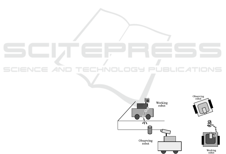
a sensor occlusion. Figure 1(a) shows an example of
the case; the working robot can not detect the target
object because it is outside of the visual angle of the
camera mounted on the robot. Figure 1(b) shows an-
other example; the working robot occludes the visual
field by its arm itself due to manipulation. In these
situations, if another robot that has a camera observes
the working robot with the target object and detects
their positions and orientations, it can assist the han-
dling of the working robot indirectly by sending the
information to the robot.
The aim of this study is to establish the functions
to achieve such an indirect assistance. More specif-
ically, This study considers how the observing robot
detects the working robot with its position, the mo-
tion of its hand, and the position and orientation of
the target object by vision. A method is proposed in
which SIFT (Scale-Invariant Feature Transformation)
is applied for detecting them and computing their po-
(a) (b)
Figure 1: Examples in which a working robot can not detect
the target object.
sitions. SIFT can generate feature points which be-
come useful correspondences for computing the 3-D
position of an object from multiple view images. The
observing robot will, therefore, be able to get valid 3-
D information to assist the working robot by applying
stereo vision theory.
In earlier studies on such an assistance, a pioneer-
ing work by (Kuniyoshi et al., 1994) has presented co-
operation tasks based on an observation for multiple
robot. A kind of indirect cooperation for assistance of
handling task has, however, not been considered yet.
The following sections describe a method for as-
sistance in indirect cooperation. Section 2 explains an
overview of cooperation and each process for assis-
458
Fujita T. and Endo T..
Observation-based Assistance by Mobile Robot for Object Handling of its Partner Robot.
DOI: 10.5220/0004592204580463
In Proceedings of the 10th International Conference on Informatics in Control, Automation and Robotics (ICINCO-2013), pages 458-463
ISBN: 978-989-8565-71-6
Copyright
c
2013 SCITEPRESS (Science and Technology Publications, Lda.)

tance including SIFT features computation and how
to obtain 3-D information. Section 3 shows results
of fundamental experiments. Finally, conclusion and
future works are provided.
2 OBSERVATION-BASED
ASSISTANCE
2.1 Overview of Cooperation
Figure 2 shows an overview of cooperation with
observation-based assistance for the object handling.
The cooperation is made by the following procedure.
(a) At first, the observing robot finds the working
robot with its hand and the target object in the sur-
rounding environment. This study assumes that
the observing robot obtains SIFT features for the
working robot in advance. The observing robot,
therefore, can detect regions for SIFT features
matching to those for the working robot. The
region that has a larger number of the matching
features than a threshold can be extracted as the
working robot. The target object can be detected
in the same way.
(b) After detecting the working robot with its hand
and the target object, the observing robot changes
the viewing location. The observing robot can ob-
tain SIFT features for them in the same way to
(a), and their correspondences. Their 3-D posi-
tions are able to be computed from the correspon-
dences in two or more views based on stereo vi-
sion theory. The observing robot then sends the
relative position information of the target object
to the working robot by a communication.
(c) When the working robot receives the relative po-
sition data of the target object to itself, it starts
planning the path of the hand to the target object.
(d) Then the working robot can control hand motion
based on the planned path. The joint angles at
each time can be calculated using Jacobian which
is computed from movement of the hand in a sam-
pling cycle time.
(e) The observing robot continuously observes hand
movementof the working robot. During the work-
ing robot moves the hand, the observing robot de-
tects 3-D information of the hand motion; that is
possible even though the observing robot stays at
the same position. Then the hand movement in-
formation is sent to the working robot by a com-
munication.
(f) According to the hand movement information re-
ceived form the observing robot, the working
robot corrects the path of hand motion if the cur-
rent path has an error to reach the target object.
Then it updates the control of hand motion as de-
scribed in (d).
In this procedure, the working robot continuously
moves its hand with the correction of the path in the
loop of (d) and (f). The observing robot also keeps
tracking the working robot and its hand motion to ob-
tain more correct motion data in the process of (e).
Updated data are then sent to the working robot.
The following sections describe key functions for
these processes: the object and position detection for
the observing robot by the use of SIFT, and the hand
motion control for the working robot.
2.2 Detection of SIFT Features
SIFT is capable of robust detection of feature points
in an image. It is also able to describe quantities of
detected features to the change of scale, illumination,
and rotation of image robustly. It is, therefore, useful
for object detection and recognition.
The processes of the detection of SIFT features
consist of extraction of feature points, localization,
computation of orientation, and description of quan-
tities of features. In the process of the extraction of
feature points, DoG (Difference of Gaussian) is used
for searching local maxima to detect the positions and
scales of features(D. G. Lowe, 1999). Some features
are then picked up from them by the process of local-
ization. The orientations for those features are then
computed, and their quantities are described.
To describe quantities of features based on the ori-
entation, surrounding region divided by 4×4 blocks at
a feature point is rotated to the direction of the orien-
tation. Making a histogram on 8 directions for each
block produces a 128(4 × 4 × 8)-dimensional feature
vector. The quantity of SIFT feature is represented by
this vector.
2.3 Object Detection
Let us suppose that the SIFT features of the working
robot, hand of its arm, and target object to be manip-
ulated are initially given to the observing robot with
their registered images. In the beginning of obser-
vation, the observing robot looks around and detects
corresponding points on the SIFT features of the ob-
ject in captured images.
In order to find the corresponding points, the 128-
dimensional feature vector, which is described in Sec-
Observation-basedAssistancebyMobileRobotforObjectHandlingofitsPartnerRobot
459
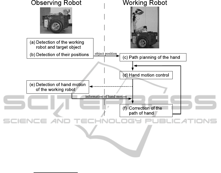
Figure 2: Procedure for the object handling based on assistance by observing robot.
tion 2.2, are calculated for each feature point in a reg-
istered image and that in an input image. Let v
Rj
be
the vector for j-th feature point in the registered im-
age, and v
Ik
be the vector for k-th feature point in an
input image. The Euclidean distance, d, between the
vectors for a feature point of the registered image and
an input image is calculated as
d =
q
(v
Rj
− v
Ik
)
T
(v
Rj
− v
Ik
) (1)
where A
T
represents the transpose of A. Then, two
candidate points which have the smallest and the
second-smallest distances of the vector, d
I1
and d
I2
,
are then picked in the input image. If these distances
satisfy d
I1
< d
I2
× 0.5, d
I1
is picked as the correspond-
ing point.
The correspondences for all feature points of a
registered image on an object to be detected are
searched in an input image. As the result, if the ratio
of the number of the corresponding point to the reg-
istered image is larger than a threshold, it is judged
the object exists at the region that covers the feature
points in the input image.
2.4 Calculation of Object Position
The observing robot can detect the 3-D positions of
the working robot and target object by parallax of cor-
responding points between two or more images ob-
served from different views. The observing robot can
extract corresponding points on the working robot or
target object in a new input image in the same way
as object detection described in Section 2.3. The
position can be calculated by general stereo vision
technique if eight or more corresponding points are
found(Q.T.Luong and O.D.Faugeras, 1997). In this
computation, image positions are normalized based
on the method given by (Hartley, 1997) to minimize
computational error.
2.5 Hand Movement Detection
In the same way to the computation of object posi-
tion, the motion of the hand of the working robot can
also be calculated from two or more different images.
In this case, the observing robot may observe at a
same position because the hand moves. The observ-
ing robot can detect the hand of the working robot
from the SIFT features and calculate its 3-D motion,
which is relative translation and orientation of the
hand of the working robot to the target object, from
the feature points and their correspondences in two
images.
2.6 Hand Motion Control by Working
Robot
The working robot can plan a trajectory for hand mo-
tion depending on the position and orientation of the
target object. This study assumes that the target ob-
ject is a cylinder and the robot knows the shape of
ICINCO2013-10thInternationalConferenceonInformaticsinControl,AutomationandRobotics
460
Figure 3: Robots and target object used in the experiment:
(a):observing robot, (b):working robot, and (c):target ob-
ject.
object beforehand for simplicity. Given the position
and orientation of the object and hand from the ob-
serving robot, the working robot plans the trajectory
of its hand to grasp the object.
This study considered simple trajectory of the
hand: the path from top of the robot to the object
consists of lines and circular arcs. When the object
is in reachable area for the hand of the working robot,
the robot moves the hand outside at middle height of
the object, then the hand approaches the object with
keeping its height.
The joint angles at each time in the arm motion are
calculated from infinitesimal differences of the hand
position and orientation in a sampling cycle time us-
ing Jacobian. The working robot checks the trajectory
whenever it receives new information of the position
and orientation of the target object and hand from the
observing robot. If the trajectory is not appropriate to
approach the object due to some errors in observation
or hand movement, the robot performs the path plan-
ning again and updates the hand trajectory in the same
manner.
3 EXPERIMENTS
3.1 Experimental Setup
The method described above has been implemented
to two wheeled-mobile robots, Pioneer P3-DX (Mo-
bile Robots Pioneer P3-DX, 2007), which is 393 mm
in width, 445 mm in length, and 237 mm in height.
Figure 3 shows those robots.
One robot shown in Figure 3 (a) has a camera,
Canon VC-C50i, which is able to rotate in pan and
tilt directions so that it is qualified as the observing
robot. A board computer, Interface PCI-B02PA16W,
was also mounted in order to process images from the
camera in observation as well as control the move-
ment of the robot. We utilized OpenCV for develop-
ing software for the image processing in observation.
Figure 4: Overview of the experiment with the result of de-
tection by the observing robot. X-Y-Z position values are
denoted for each; O
1
, O
2
, O
3
: observation locations (view
angles are also denoted), W: real position of the working
robot, OW: detected position of the robot, A: position of
hand of the working robot, OA: detected hand position, T:
position of the target object, OT: detected position of the
object. E shows error between real and detected values.
Another robot shown in Figure 3 (b) has a 6-DOF
manipulator to be the working robot. A 1-DOF hand
is attached at the end of the manipulator. The hand is
140 mm in width, 160 mm in length, and 100 mm in
height. This robot doesn’t have any sensor to detect
an object.
Figure 3 (c) shows the target object used in the
experiment. It was a cylindrical can, which was 65
mm in diameter and 390 mm in height. Texture pat-
terns were attached on its surface so that the observing
robot can detect feature points easily.
Figure 4 shows an overview of this experiment.
The working robot stayed at one position, denoted as
W. The observing robot looked for the working robot,
its arm, and the target object at the point O
1
and de-
tected them. It then moved to the point O
2
and O
3
and calculated 3-D positions of the objects from the
views at the points. These detected position infor-
mation was sent to the working robot. The working
robot then started moving its arm to handle the target
object. The observing robot kept tracking the hand
motion and calculated 3-D motion of the hand of the
working robot continuously.
3.2 Detection of Working Robot
and Target Object
Figure 5 shows images registered in the experiment:
(a) hand of the working robot, (b) the working robot,
and (c) the target object. Rectangle regions were reg-
istered for them as shown in the figures. SIFT features
in each region were extracted by the method described
in Section 2.2. These features were used for definition
and detection of them by the observing robot. The ob-
Observation-basedAssistancebyMobileRobotforObjectHandlingofitsPartnerRobot
461
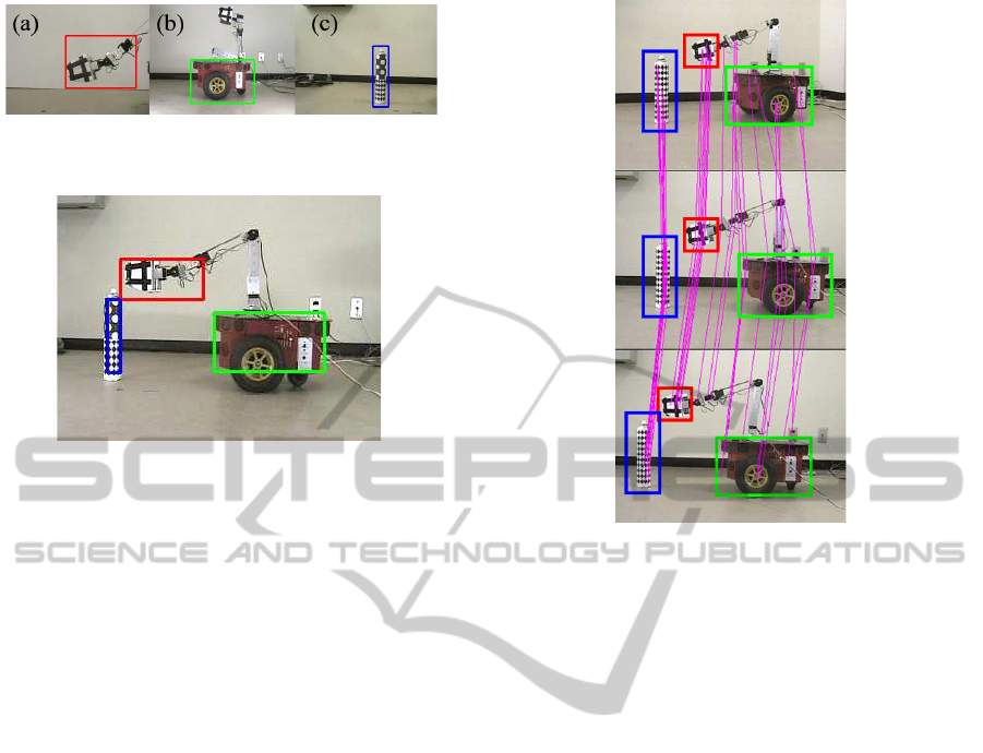
Figure 5: Registered images: (a):hand of the working robot,
(b):the working robot, and (c):target object.
Figure 6: Detected Regions for the working robot (green
rectangle), its hand (red), and target object (blue).
serving robot extracted SIFT features from an input
image and obtained correspondences for the working
robot, its arm, and the target objects respectively to
detect them. A region in which the ratio of the number
of corresponding points between the registered image
and an input image is larger than 0.4 was extracted, as
the detection of each target. Figure 6 shows detected
regions for the working robot, its hand, and the target
object. These regions are indicated by green, red, and
blue rectangles respectively.
3.3 Detection of Positions
The observing robot changed the position from O
1
to
O
2
and O
3
in Fig. 4 to observe the working robot with
its hand and the target object in different visual an-
gles.
Figure 7 shows the images which were taken by
the observing robot at those view points. SIFTfea-
tures were extracted from these images, and the cor-
responding points on each region between them were
computed. The correspondences between two images
at adjacent view points are shown by the connections
of pink line in Fig. 7. The 3-D positions for those
targets were calculated from parallax information of
these corresponding points based on stereo vision the-
ory.
The obtained positions of them are described in
Fig. 4: OW for the working robot, OA for the hand,
and OT for the target object. The error values to real
positions are also described below the detected posi-
tions respectively. The maximum error was 65 mm
for the position in theY direction for the target object.
The authors consider this error is in the acceptable
Figure 7: Detected correspondences of SIFT features (con-
nected by pink lines) for the images at the view points O
1
(upper row), O
2
(middle row), and O
3
(lower row). The
rectangles indicate detected regions for the working robot
(green), its hand (red), and the target object (blue).
range for object handling from the size of the hand.
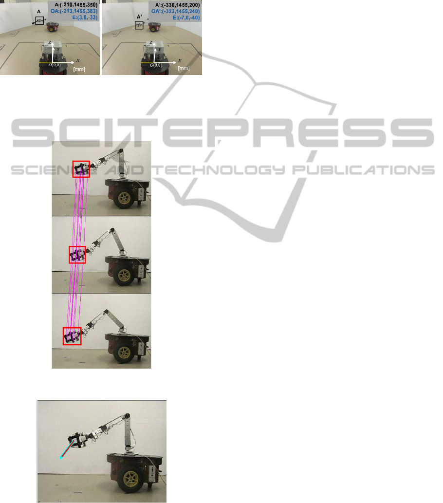
3.4 Detection of Hand Movement
Figure 8 shows an overview of the hand movement
detection. The observing robot stayed at O
3
after
detecting hand position of the working robot; then
tracked the hand movement during the working robot
moved its hand from the position A to A
′
. The ob-
serving robot obtained corresponding points of SIFT
features in the region of hand in the same way as po-
sition detection. Figure 9 shows detected correspond-
ing points of SIFT features from three images in the
sequence of hand movement for the working robot.
Each correspondence is connected by pink line each
other.
A hand position was computed for each image,
and a translation vector was obtained from the posi-
tions. The detected vector was (−110, 0, −143)
T
to
the real vector (−120, 0, −150)
T
. The Y direction of
the hand movement did not change because weak per-
spective projection was supposed in the hand move-
ment. Figure 10 shows extracted translation vector of
the hand. The result shows that appropriate motion
vector was detected.
In this experiment, the time taken for computing
SIFT features and finding the corresponding points
was from 339 to 616 ms per one image; it depended
ICINCO2013-10thInternationalConferenceonInformaticsinControl,AutomationandRobotics
462
on the number of the feature points. The authors
consider that the time enables the observing robot to
detect the hand motion of the working robot in real
time. Moreover, if it is possible to reduce picked fea-
ture points more effectively, the corresponding points
would be found faster.
Figure 8: Overview of the detection of hand movement.
The working robot moved its hand from the position A (left
panel) to the position A
′
(right panel). OA and OA
′
show
detected positions by the observing robot. The error value
to the real position, E, are also denoted.
Figure 9: Detected corresponding points of SIFT features
on hand of the working robot in hand movement.
Figure 10: Detected translation vector of the hand (red ar-
row) in hand movement of the working robot. The blue
arrow is the real movement vector.
4 CONCLUSIONS
This study described a method for assisting a work-
ing robot’s object handling task based on an observa-
tion by another cooperative partner robot in the sit-
uation that the working robot can not perceive the
object. The fundamental experiments confirmed pro-
cesses in the proposed method: detection of the work-
ing robot, its hand, and the target object based on
correspondences SIFT features, positions computa-
tion for them, and detection of hand movement of the
working robot. Our future work will proceed with
consideration orientations of the robot and objects,
and expand this method to practical case toward real-
time cooperation.
REFERENCES
D. G. Lowe (1999). Object recognition from local scale-
invariant features. In Proc. of IEEEInternational Con-
ference on Computer Vision, pages 1150–1157.
Hartley, R. (1997). In defense of the eight-point algorithm.
IEEE Transactions on Pattern Analysis and Machine
Intelligence, 19(6):580–593.
Kuniyoshi, Y., Rickki, J., Ishii, M., Rougeaux, S., Kita, N.,
Sakane, S., and Kakikura, M. (1994). Vision-based
behaviors for multi-robot cooperation. In Proceed-
ings of the IEEE/RSJ/GI International Conference on
Intelligent Robots and Systems ’94, volume 2, pages
925–932.
Mobile Robots Pioneer P3-DX (2007). In
http://www.mobilerobots.com.
Q.T.Luong and O.D.Faugeras (1997). Self-calibration of a
moving camera from point correspondences and fun-
damental matrices. International Journal of Computer
Vision, 23(3):261–289.
Observation-basedAssistancebyMobileRobotforObjectHandlingofitsPartnerRobot
463
