
The Effect of Magnetomechanical Resonance on Stokes Vector in
Magneto Optical Crystals
I. Linchevskyi
Kyiv Polytechnical Institute, National Technical University of Ukraine, Kyiv, Ukraine
Keywords: Magneto-Optical Crystal, Magnetomechanical Resonance, Stokes Vector.
Abstracts: The peculiarities of changes in the polarization of light passing through a crystal have been investigated for
the case of magnetomechanical resonance within the model of longitudinal oscillations of a magnetooptical
crystal shaped as a thin rod. It is shown that the components of the Stokes vector experiencing frequency
amplitude and phase changes.
1 INTRODUCTION
It was shown (Linchevskyi and Petrishchev, 2011)
that mechanical stresses arise in a magneto-optical
crystal (MOC) under the conditions of
magnetomechanical resonance (MR). These stresses
cause additional changes in the magnetization and
rotation of the polarization plane of light due to the
Faraday effect.
If the magnetic field direction differs from the
propagation direction of light, a quadratic
birefringence (Cotton–Mouton) effect of comparable
magnitude arises in cubic ferrimagnets
simultaneously with the Faraday effect (Smolenskii et
al., 1975). The distribution of mechanical stress over
the MOC volume at MR makes the crystal
magnetization inhomogeneous. This circumstance
hinders the use of a Mueller matrix for an active
medium exhibiting linear and quadratic magneto-
optical effects when the MOC is homogeneously
magnetized (Tron’ko, 1970).
In this paper, we report the results of studying the
amplitude and phase-frequency relations for the
Stokes vector at the output of an inhomogeneously
magnetized MOC using Mueller matrices.
2 MATHEMATICAL MODEL
Figure 1 shows an MOC shaped as a thin rod of
length 2l oriented along the axis, which coincides
with the propagation direction of polarized light with
a wave vector k. The light-magnetization axis of
MOC coincides with the axis OZ. The electric field
component
y
E corresponds to the highest velocity
of light propagation in the MOC. The magnetic
field vector contains a constant component
0
H
directed along the axis plays the role of bias field.
Its value is chosen so as to provide maximum
sensitivity of ferrimagnet magnetization to strains.
According to (Bozorth, 1951), the value
0
H
should provide magnetic induction at a level
of
0.6
s
B
in the ferrimagnet (
s
B is the saturation
induction).
Figure 1: Schematic of the mathematical model: (1) a
magneto-optical crystal.
1
E
E
k
0
H
H
z
0
-
l
x
l
y
65
Linchevskyi I..
The Effect of Magnetomechanical Resonance on Stokes Vector in Magneto Optical Crystals.
DOI: 10.5220/0004270400650067
In Proceedings of the International Conference on Photonics, Optics and Laser Technology (PHOTOPTICS-2013), pages 65-67
ISBN: 978-989-8565-44-0
Copyright
c
2013 SCITEPRESS (Science and Technology Publications, Lda.)

A harmonically oscillating field
* it
Hhe
of
specified frequency is directed in the drawing plane
and makes an angle
with the vector k. The
amplitudes of the fields and satisfy the requirement
0
HH
. MOC is maintained in a free state (i.e.,
is not clamped by the design elements) to provide
high Q mechanical vibrations.
Under these conditions, periodic (with frequency
) mechanical stresses arise along the axis due to
the magnetostriction in MOC; these stresses induce
additional changes in the magnetization
J . Note
that, within the thin-rod model, the change in the
position of the field component with respect to the
longer rod axis may change the amplitude of
longitudinal mechanical stresses. We assume that the
rod performs longitudinal vibrations and that there
are no strains in the transverse direction with respect
to the rod axis.
At
0
, the light transmission through an
inhomogeneously magnetized MOC is accompanied
by both Faraday and Cotton–Mouton effects. The
components of the magnetization vector can be
written as:
*
*
0
sin
cos
(1)cos
cos
y
z
JH
z
J
mHH
l
,
(1)
where:
1
0,77
ss
JK
,
s
J - is the saturation
magnetization;
s
- is the saturation magnetostriction;
and
1
K is the MOC anisotropy constant, m
-
piezomagnetic constant.
To construct the Mueller matrix, we divide the
MOC into several layers, each of thickness Δz. This
value is chosen to be small enough to neglect
magnetization inhomogeneity within the layer. Then,
using the Mueller matrix for a homogeneous medium,
which exhibits Faraday and Cotton–Mouton effects
simultaneously (Tron’ko, 1970 ), and taking into
account relations (1), one can express the Mueller
matrix of the sample,
M
in terms of the product of
matrices of its homogeneous layers:
jn
j
jn
M
Mz
,
(2)
where:
l
n
z
is the number of layers (in the
limit,
n ),
11212
112 12
21
10 0 0
0
0
00
j
cscss
M
scc cs
sc
,
121
2
cos 2 ; cos ; sin 2 ;
sin
cazcbzsaz
sbz
,
*
0
cos
2(1)cos
cos
jz
am HH
l
2
2sinbH
,
12iQ
,
Y
, ,Y
and
are, respectively, the
Young’s modulus, density, and magnetic
susceptibility of the magnetized rod;
- the
proportionality factor between the angle of rotation
of polarization plane, normalized to the length unit
of MOC and its magnetization;
- relative phase
shift between the components of the field
x
E and
y
E
.and is the specific phase shift between the field
components and at a specified field. Using matrix
(2), we determine the variable components of the
Stokes vector at the MOC output for
0
45
using
the example of yttrium garnet ferrite (
1253
OFeY ):
33
2 15mm, 138GPa, 5,17 10 kg m ,lY
23
1
1060T, 6,2 10 J m ,mK
6
42
1.4 10 , 200, 11,4êÀ m,
1,3deg À, 3,9 10 deg×m À
ss
QJ
Parameters of the magnetic field were
0
635À m, 20 À mHh
.
For definiteness, we assume that the initial light
is plane-polarized with an azimuth of the electric
vector oscillation plane equal to 45° (the Stokes
vector at the input is
1
1, 0,1, 0V
). At the MOC
output, the Stokes vector has the form
21
VMV
(3)
Following the designations of the Stokes vector
components (V) = (I, M, C, S) according to
(Shercliff, 1962), we should note that the elements
M, C, and S of the vector
2
V
contain both
constant and variable components:
PHOTOPTICS2013-InternationalConferenceonPhotonics,OpticsandLaserTechnology
66
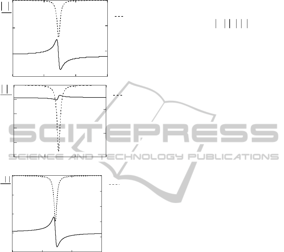
Figure 2: Linear-frequency dependences the magnitude (—)
and the initial phase shifts (---) of the
,,
M
CS Stokes
vector elements.
0
2
0
0
1
0
M
C
S
i
i
i
M
me
V
C
ce
S
se
(4)
The constant components
000
,, SCM are
determined by the magnetic field
0
H , whereas the
variable components
s
,mc and their initial phase
,,
M
CS
depend on a number of factors: H
,
0
H and
(at MR).
Figure 2 shows the results of calculating the
magnitude dependence
M
, C , S , and the
initial phase
000
,,
M
CS
of the variable
components
,,mcs of the linear frequency
f
.
Note that the component for polarized light can also
be found from the relation:
2
2
00
2
0
()
()1
C
M
S
i
i
i
Mme Cce
Sse
(5)
3 CONCLUSIONS
Magneto mechanical oscillations induced in MOC
due to the change in the variable component of
magnetization change the polarization of light.
When the direction of the dc (bias) magnetic
field and the light propagation direction does not
coincide with the propagation direction of light, the
inhomogeneity of MOC magnetization due to the
MR causes additional amplitude and
phasefrequency changes in the variable components
of ellipticity and the components X and Y of
polarized light.
The results obtained can be used to determine
the MOC material constants and design magnetic
field sensors on their basis.
REFERENCES
Linchevskyi, I., Petrishchev, O., 2011. Ukr. J. Phys.56
(5), 496.
Smolenskii, G.,Pisarev, R. , Sinii, I.,1975. Usp.Fiz. Nauk
116 (2), 231.
Tron’ko, V, 1970. Opt. Spectrosc. 29 (2), 354.
Bozorth, R,1951. The book, Ferromagnetism (Van
Nostrand, Princeton, NJ.
Shercliff, W, 1962. The book, Harvard Univ. Press,
Cambridge, MA.
170 175 180
165
180
deg
,
M
170
0.8
0.6
160
f
, kHz
M
165
170
175
180
0
0.2
0.4
0.6
0.8
f
,kHz
20
10
C
deg,
C
165
170 175
180
0.014
0.016
0.01
8
6
4
2
0
0.012
S
S
,deg
f
, kHz
TheEffectofMagnetomechanicalResonanceonStokesVectorinMagnetoOpticalCrystals
67
