
Reconstructing Archeological Vessels from Fragments using Anchor
Points Residing on Shard Fragment Borders
Zexi Liu
1
, Fernand Cohen
1
and Ezgi Taslidere
1
1
Department of Electrical and Computer Engineering, Drexel University, Philadelphia, U.S.A.
Keywords: Intrinsic Geometric Features, Curvature, Inflection, Mending, Archeological Shards, Global Constraint.
Abstract: This paper presents a method to assist in the tedious process of reconstructing ceramic vessels from
excavated fragments. The method models the fragment borders as 3D curves and uses intrinsic differential
anchor points on the curves. Corresponding anchors on different fragments are identified using absolute
invariants and a longest string search technique. A rigid transformation is computed from the corresponding
anchors, allowing the fragments to be virtually mended. A global constraint induced by the surface of
revolution (basis shape) to decide on how all pairs of mended fragments are coming together as one global
mended vessel is used. The accuracy of mending is measured using a distance error map metric. The method
is tested on a set of 3D scanned fragments (313 pieces) coming from 19 broken vessels. 80% of the pieces
were properly mended and resulted into alignment error at the scanner-resolution-level. The method took 59
seconds for mending pieces plus 60 minutes for 3D scans as compared to 12 hours for stitching manually.
1 INTRODUCTION
The mending of unearthed archeological ceramic
shards to reconstruct vessels that the fragments once
formed is currently a tedious and time-consuming
process. Nevertheless, it is a vital step in interpreting
the archeological record and an important
component in understanding and preserving cultural
heritage.
There are a variety of existing techniques for
characterizing and reconstructing fragments. They
can be classified into four categories, which are
point-to-point, curve, surface, and shape descriptor
matching. The unifying idea rests on finding
corresponding parts, matching, aligning, and gluing
all matching parts together.
Ucoluk and Toroslu (Ucoluk and Toroslu, 1999)
proposed a 3D curve matching approach for the
mending of thin-shell fragments, based on string
matching of the curvature and torsion values on the
discrete 3D curve points. The string matching
algorithm is further elaborated in (Rodriguez, Last et
al., 2004).
For thick-shell fragments, i.e. broken pieces with
large contact surfaces, Papaioannou et al.
(Papaioannou and Karabassi, 2003) presented a
method based on polygonal surfaces. They introduce
a matching error between complementary surfaces
that exploits the z-buffer algorithm. This method is
then extended to incorporate curve matching ideas.
In this paper, we select a feature-based approach
that identifies corresponding anchor points on
different shards to help in the mending process. The
main advantages of our method are: (i) the
extraction of novel anchor points residing on the
fragments’ borders. These are differential intrinsic
points sometimes not easily seen by the naked eyes,
hence the method looks at features that can go
beyond human visual mending; (ii) introducing a
simple and easy method for the extraction of the
fragment border through the use of a Delaunay
triangulation on the 3D data, followed by the
detection of those triangles edges that are not shared
by two abutting triangles. It results into a set of self-
induced ordering of points of the border edges by
simply following the end points of the abutting
border edges in a clockwise or an anticlockwise
direction. These ordered endpoints are the fragment
border curve points; (iii) establishing
correspondences between anchor points on
fragments through the use of absolute invariants and
a novel string matching method; (iv) introducing a
global constraint induced by the surface of
revolution on how all pairs of mended fragments are
coming together as one global mended vessel; and
finally (v) we run a comparative analysis between
our automatic mending method with that of an
80
Liu Z., Cohen F. and Taslidere E..
Reconstructing Archeological Vessels from Fragments using Anchor Points Residing on Shard Fragment Borders.
DOI: 10.5220/0004231800800083
In Proceedings of the International Conference on Computer Vision Theory and Applications (VISAPP-2013), pages 80-83
ISBN: 978-989-8565-48-8
Copyright
c
2013 SCITEPRESS (Science and Technology Publications, Lda.)
expert manually mending the pieces both in terms of
time and performance. We found that compared to
expert mending, the automatic mending process on
the 313 fragments took about 59 seconds for the
mending plus approximately 60 minutes for the
fragments to be 3D scanned as compared to 12 hours
for stitching by the experts.
2 ALIGNMENT WITH ANCHOR
POINTS
There are several geometrical landmarks, for
instance, inflection points, corner points, and zero-
torsion points, that are intrinsic and preserved under
a rigid transformation. These are the anchor points
that we use in this paper for mending the fragments.
These anchor points are theoretically pinned in the
differential geometry of curves via the Frenet
Frames (Kühnel, 2006).
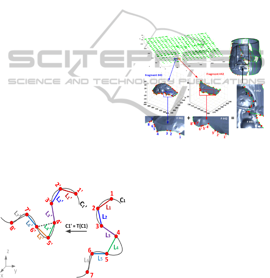
2.1 Constructing Absolute Invariants
Since length is preserved under 3D rigid maps and
are absolute invariants, we can construct a sequence
of absolute invariants by considering the sequence of
length of lines between the two consecutive anchor
points (e.g., lines between points #1-2, points #2-3,
etc. as shown in Figure 1). Note that there is an
anchor point missing between points #4 and #5 on
curve
. This will not affect the matching given that
there is enough number of anchor points. For a curve
with n anchor points, the sequence of length is
denoted by
,
,…,
. For the curve
in
Figure 1, there are 7 anchor points on the curve.
Figure 1: Absolute invariants with anchor points with
some possibly missing. The algorithm in section 2.3 will
always find the longest matching string.
Thus there are 6 lines. When curve
undergoes a
rigid transformation (
), the transformed
lines sequence has also the same number of elements
,
,…,
as the original curve
. And
we need to find the sequences of elements in that
invariant vectors in and
that correspond.
Towards that end we introduce a “longest string
search” technique, which is similar to the “list-
matching algorithm” (Bratko, 1990) for establishing
the correspondence and declaring the match. In
order to recover the rigid transformation and mend
the fragments, at least three pairs of matched points
is required, i.e., the minimum edge string length
should be 2.
Figure 2: Fragment mending based on anchor points (red
dots).
2.2 Longest String Match
As the anchor points and the joining edges between
them are ordered, we can find the longest string of
consecutive edges that lie on two fragments whose
respective length absolute invariants match. This is
necessary as invariant values on two different
fragments coming from different vessels may be
equal to within our allowable error (2-5%) if
considered individually and not as a string. A set of
two or more consecutive anchor points and their
corresponding invariants are considered to be a
“string” (e.g., the set ,1,2,… on one
fragment and the set ,1,2,… on another
fragment). We allow for a small error % (2-5%) in
the values of the invariants, to declare matching
edges in that string search. The sets ,1,
2, … and ,1,2,… of anchor points are
declared as matching if |
|0.05∙
for every pair in the two sets. In case that there are
ReconstructingArcheologicalVesselsfromFragmentsusingAnchorPointsResidingonShardFragmentBorders
81
missing points, for example, in Figure 1,
,
then the distance
will be discarded and the
distance between points 4
and 6
will be calculated,
then
. Generally speaking, if we encounter
an “unmatched” segment, we will always jump over
one point and check its next anchor point. As this
process is recursive we can deal with more than one
missing point.
The rigid transformation
,
can be
recovered from three pairs of matched points, or
estimated from more matched anchor points using a
least square error (LSE) estimation method
(Umeyama, 1991).
Once the transformation parameters are found,
the fragments are mapped into the same coordinates
system by undoing the rigid transformation and the
fragments are aligned through their common curve
segment.
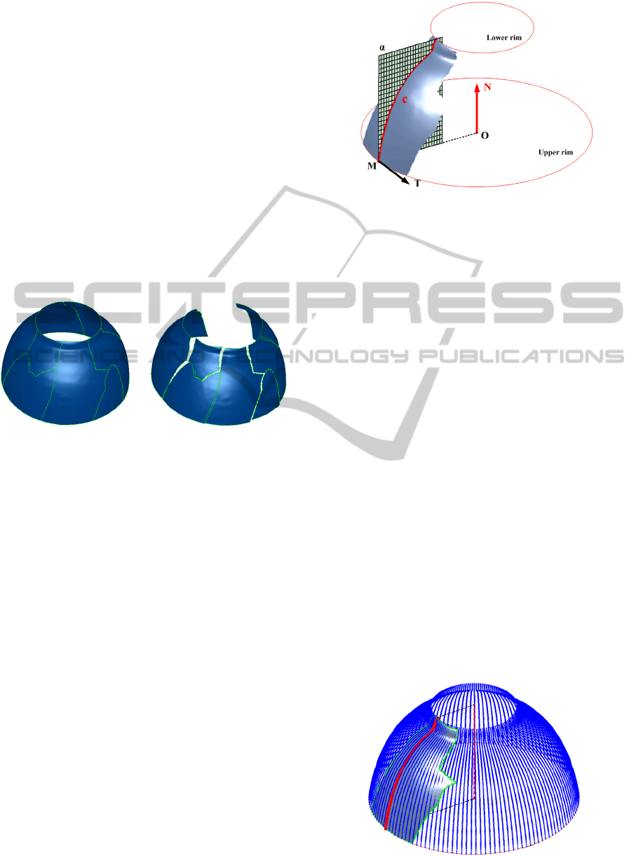
Figure 3: With/without global optimization.
2.3 Global Optimization
The mending described in the previous section and
shown in Figure 2 is a pair wise mending process. It
is conceivable that alignment errors will accumulate,
rendering the reconstruction result less than
satisfactory (See right hand side of Figure 3). For
vessels that are axially symmetric, this problem can
be solved by adopting the surface of revolution as a
global constraint. The surface of revolution is
obtained by going through the following steps:
1. Extract the “profile curve” (Willis, Orriols et al.
2003).
2. Obtain the symmetry axis (revolution axis).
3. Rotate the profile curve about the axis.
4. Generate a rotation surface.
5. Use the surface as a global optimization “basis”.
Steps 1 and 2 are shown in Figure 4. The lower rim
and upper rim are obtained by fitting a circle to the
fragment border segments. Of all the fragment
border segments, the one with the smallest fitting
error is the rim. M is a point on the rim. T is the
tangent vector of the upper rim at M. We can find a
plane α that is orthogonal to T and containing M.
Figure 4: Obtain profile curve and symmetric axis.
The cross-section curve c is the profile curve.
Steps 3 and 4 are shown in Figure 5. Here we
rotate the profile curve about the revolution axis to
generate a set of curves which constitute the rotation
surface. This rotation surface is used in our mending
process as a basis shape, where the fragments are not
only aligned to each other, but are also aligned to
this surface. With this global optimization
constraint, the result is improved as shown on the
left hand side of Figure 3.
Note that before a basis shape is found,
fragments with no upper and lower rims are set
aside, and only fragments that do possess both rims
are found and possibly mended using the pair wise
invariants approach. After we obtain a mended
fragment with both upper and lower rims, we extract
the profile curve and the rotation surface (steps 1-5).
We then improve on the mending for all fragments
using the basis shape as a global constraint.
3 EXPRIMENTS
Excavated shards are scanned using a Konica
Minolta Vivid 910 3D scanner. The scanned raw
data (discrete 3D points) is represented as triangle
mesh.
Figure 5: Generate a rotation surface.
VISAPP2013-InternationalConferenceonComputerVisionTheoryandApplications
82
We define the residual error for each fragment as the
mean point-to-point distance map between the
mended fragments and the original unbroken jar.
The mean distance is normalized against the
resolution of the scanner. In all our experiments, the
19 vessels were scanned prior to breaking them into
fragments, with the latter being also scanned
individually.
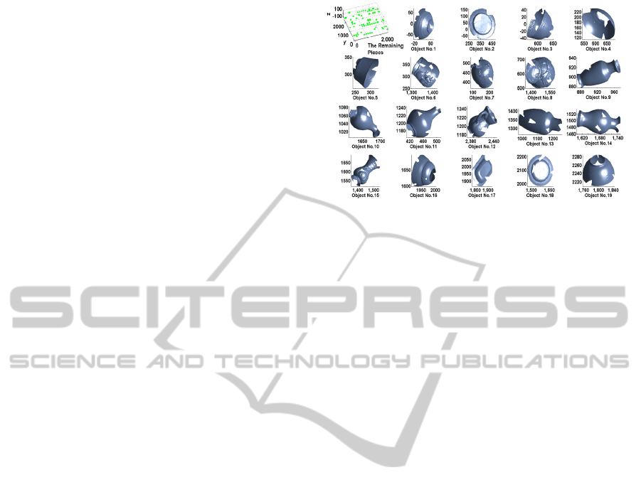
The described method is tested on 313 fragment
pieces coming from 19 different ceramic objects.
Each fragment is scanned separately.
The mending process for one object is shown in
Figure 2 with all the anchor points showing for two
mended pieces on the vessel. A total of 245 out of
313 fragments were mended properly to their correct
vessels as shown in Figure 6. There were 68 pieces
that could not be mended (See “The Remaining
Pieces” subplot on the upper left of Figure 6) due to
insufficient anchor points.
The entire mending process took 59 seconds on
an Intel i7 processor PC with 18 GB memory for the
mending process, and approximately 60 minutes for
the scanning. This is to be compared to 12 hours for
the stitching done by the experts.
80% fragments were properly mended with
distance map errors at or below the scanner
resolution, i.e. the residual errors normalized by the
scanner resolution were all below or close to 1.
4 CONCLUSIONS
We present a methodology to mend fragments into
vessels based on anchor points on fragment borders.
This work is part of a collaborative project for which
the main objective is to develop and utilize novel
computer vision technology to assist in the
reconstruction of ceramic artifacts recovered from
an excavation site. The work has focused on the use
of one aspect (fragments borders) amongst many
embedded in the fragments. This, in conjunction
with many other aspects such as markings, texture,
or surface information, could be collectively used as
enabling technology helping in the mending process.
This is particularly important if the extracted anchor
points in the paper are absent due to complete
erosion of the fragments borders on abutting
fragments, which would limit the success of such a
method. The whole project as an application of
computer vision in archaeology is unique as an
enabling technology for timely analysis,
interpretation, and presentation of history evidence.
It is also considered as a great need by the U.S.
Department of the Interior National Park Service.
Figure 6: Mended objects.
ACKNOWLEDGEMENTS
This work is supported by the National Science
Foundation IRIS Division under grant #0803670.
REFERENCES
Bratko, I. 1990. Prolog Programming for Arificial
Intelligence. London, UK, Addison Wesley.
Kühnel, W. 2006. Differential geometry : curves - surfaces
- manifolds. Providence, R.I., American Mathematical
Society.
Papaioannou, G. and E. A. Karabassi 2003. "On the
automatic assemblage of arbitrary broken solid
artefacts." Image and Vision Computing 21(5): 401-
412.
Rodriguez, W., M. Last, et al. 2004. "3-Dimensional curve
similarity using string matching." Robotics and
Autonomous Systems 49(3-4): 165-172.
Ucoluk, G. and I. H. Toroslu 1999. "Automatic
reconstruction of broken 3-D surface objects."
Computers & Graphics 23(4): 573-582.
Umeyama, S. 1991. "Least-Square Estimation of
Transformation Parameters Between Two Point
Patterns." IEEE Transactions on Pattern Analysis And
Machine Intelligence 13(4): 376-380.
Willis, A., X. Orriols, et al. 2003. Accurately Estimating
Sherd 3D Surface Geometry with Application to Pot
Reconstruction. CVPR Workshop: ACVA. Madison,
WI, USA, IEEE Computer Society.
ReconstructingArcheologicalVesselsfromFragmentsusingAnchorPointsResidingonShardFragmentBorders
83
