
Automatic Modeling of an Orthotic Bracing for Nonoperative
Correction of Pectus Carinatum
João L. Vilaça
1,5
, Pedro L. Rodrigues
1,2
, António H. J. Moreira
1,2
, João Gomes Fonseca
1
,
A. C. M. Pinho
3
, Jaime C. Fonseca
4
and Nuno Rodrigues
5,6
1
ICVS/3B’s - PT Government Associate Laboratory, Braga/Guimarães, Portugal
2
Algoritmi Center, School of Engineering, University of Minho, Guimarães, Portugal
3
Mechanical Department, University of Minho, Guimarães, Portugal
4
Industrial Electronics Department, University of Minho, Guimarães, Portugal
5
DIGARC – Polytechnic Institute of Cávado and Ave, Barcelos, Portugal
6
HASLab/INESC TEC, University of Minho, Braga, Portugal
Keywords: Pectus Carinatum, Nonoperative Treatment, 3D Image Processing, Mesh Processing.
Abstract: Pectus Carinatum is a deformity of the chest wall, characterized by an anterior protrusion of the sternum,
often corrected surgically due to cosmetic motivation. This work presents an alternative approach to the
current open surgery option, proposing a novel technique based on a personalized orthosis. Two different
processes for the orthosis’ personalization are presented. One based on a 3D laser scan of the patient chest,
followed by the reconstruction of the thoracic wall mesh using a radial basis function, and a second one,
based on a computer tomography scan followed by a neighbouring cells algorithm. The axial position where
the orthosis is to be located is automatically calculated using a Ray-Triangle intersection method, whose
outcome is input to a pseudo Kochenek interpolating spline method to define the orthosis curvature. Results
show that no significant differences exist between the patient chest physiognomy and the curvature angle
and size of the orthosis, allowing a better cosmetic outcome and less initial discomfort.
1 INTRODUCTION
Pectus Carinatum is a deformity of the chest wall
characterized by an anterior protrusion of the
sternum and ribs. It occurs in approximately one out
of every 1500 children (about 80% of patients are
male). Current treatment for Pectus Carinatum
includes both surgical and nonsurgical options.
Despite the success of operative approaches, the
related surgery complications (e.g. bleeding), scars
and postoperative pain, present considerable
drawbacks of these more invasive techniques
(Alexander et al., 2009).
Based on the fact that the anterior chest wall is
malleable during puberty, many authors advocate the
benefits of nonoperative approaches to induce chest
wall remodelling (Frey et al., 2006); (Goretsky et al.,
2004). Although this treatment option has been
shown to provide positive results over time, some
parents find it difficult to keep their children from
taking off the brace (most of the times due to
wearing discomfort), which reduces the overall
therapeutic process efficiency (Stephenson and Du
Bois, 2008).
The present work proposes two different
approaches for the automatic orthosis
personalization: one based on a 3D laser scan and
another on a computer tomography (CT) scan of the
chest.
Afterwards, the system developed in (Vilaça et
al., 2009) is applied to automatically model and
bend the orthosis bar, according to each patient
morphology.
2 METHODS AND RESULTS
This section describes all methods to automatic
determine the array points that are used in (Vilaça et
al., 2009).
71
L. Vilaça J., L. Rodrigues P., H. J. Moreira A., Gomes Fonseca J., C. M. Pinho A., C. Fonseca J. and Rodrigues N..
Automatic Modeling of an Orthotic Bracing for Nonoperative Correction of Pectus Carinatum.
DOI: 10.5220/0004221100710074
In Proceedings of the International Conference on Computer Vision Theory and Applications (VISAPP-2013), pages 71-74
ISBN: 978-989-8565-48-8
Copyright
c
2013 SCITEPRESS (Science and Technology Publications, Lda.)
2.1 Thoracic Wall Reconstruction
This stage reconstructs the anterior and posterior
thoracic wall according to two different sets of input
data, namely CT imagiology and 3D scanner dat.
Since CT scans remain the primary choice for
preoperative imaging of Pectus Carinatum, a CT
data set is available in most patients, providing
useful information about abnormal thoracic anatomy
and symmetry defects. Therefore, one has
implemented an algorithm that automatically
segments all skin points and generates a 3D mesh
from a CT data set. The process starts with a pre-
processing stage that performs a smooth operation
on the CT data (using a Gaussian filter) and
calculates its gradient volume magnitude. Then, all
image pixels are vertically and horizontally tracked
by recursively selecting all first voxels belonging to
the image gradient (skin points). These voxels are
input to a neighbouring cells algorithm, where each
voxel of a cubic grid cell is classified as lying above
or below an 800 iso-surface threshold. A tri-linear
interpolation is then used to reconstruct a skin
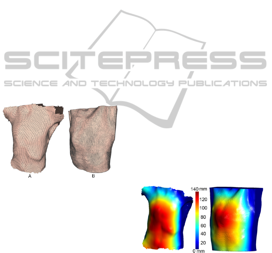
surface mesh from CT data (Figure 1 – B).
Figure 1: 3D Mesh representation from a 3D scan (A) and
using a 3D CT data set.
Although CT scans have been the main analysis
option to assess Pectus Carinatum severity,
sometimes these are not available or are deprecated.
For these patients, an inoffensive and radiation-free
3D laser scan using the FastSCAN system can be a
much better choice, avoiding the need of a CT scan,
and the related radiation, to reconstruct the thoracic
wall. Exploring such an option, one was able to
achieve a minimal error acquisition of
approximately 1 mm, by attaching the system
reference to the 10º left rib.
The unorganized point clouds acquired from the
3D scan, containing outlier’s points, noise and non-
uniformities in thickness and spacing were used to
reconstruct the thoracic wall mesh surface. The
algorithm used to reconstruct a smooth surface from
the raw points of the 3D scanner was based on
Radial Basis Functions (RBFs) (Savchenko et al.,
1995).
The data misalignments and surface holes (when
two or more samples overlap in the same Oxyz
plane) were eliminated by modifying the voxel size
and an adaptive kernel window during
reconstruction. In the end, a 3D mesh was created
representing the thoracic wall (Figure 1 - A).
After the mesh reconstruction, some surface
holes can still exist. This situation was more
frequent when the mesh was created using the 3D
scanner, due to patient movements during the
acquisition and light interference. To overcome this
problem, a correction filter was developed, that
searches for accentuated changes on the X and Y
components of the discrete signal derivative. For
each triangle T of the surface mesh whose partial
derivative value is higher than a given threshold,
when compared to its neighbourhood triangles
(within a defined radius R), the triangle vertices
coordinates within R were merged together
according to its neighbourhood maximum values.
The outcome of this process was input to a
Laplacian smooth method to reduce the shrinking
effect.
2.2 Highest Sternal Protrusion
The surface mesh created on the previous section
was input to a Ray-Triangle intersection method,
which was used to compute the minimal distance
between two triangle meshes: the thoracic wall mesh
(Ts) and a plane mesh reference (Tp) which size was
adjusted for the Ts size.
Figure 2: Illustration of the Ray-Triangle intersection
method results, used to automatically determine the region
of the greatest sternum protrusion.
In the end, the difference between each plane facet
triangle and the thoracic facet triangle was
determined. Based on these distances, the thoracic
triangle facets were coloured according to the
VISAPP2013-InternationalConferenceonComputerVisionTheoryandApplications
72
colour-map defined on the colour bar in Figure 2.
The most anterior prominent sternal protrusion (red
area, Figure 2), was chosen for orthosis placement
and for the sizing of the cushioned compression
plates of the anterior position.
2.3 Orthosis Automatic Modelling
The higher sternum protrusion point and a normal
along Oy were firstly used to define an axial plane to
place the orthosis. Then, a method was implemented
to cut the thoracic wall mesh that intersects this
plane.
The cutting result was a set of points that were
input to a method that determines a pseudo
Kochenek interpolating spline with a control
continuity and tension parameter (Kochanek and
Bartels, 1984).
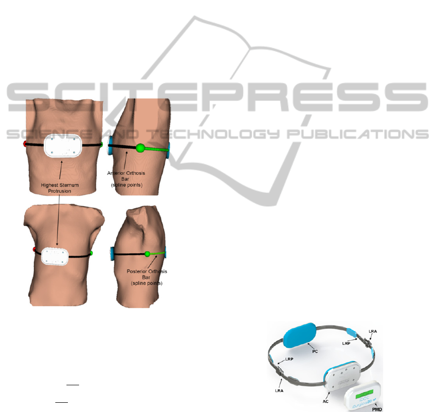
Figure 3: Bar modelling representation.
The continuity/discontinuity of the first derivative of
at a key spline position was defined according to
Equation 1:
Out
Spline
=
∙
∓
(1)
where c is the continuity factor (experimentally
calculated – c0.2.
This kind of spline produced fewer oscillations
(when the thoracic mesh data is not smooth), had no
overshoots, and preserved the data monotonicity. By
using this spline it was possible to determine all
regions where the prosthesis is placed, avoiding skin
irregularities that are not relevant for the orthosis
modelling.
The following methodology was then used to
determine the final orthosis shape (Figure 3):
1) Determination of the rightist and leftist spline
points which defines a coronal plane along the
thoracic wall (red and green spheres, Figure 3).
Each of these locations defines two planar
regions (which size depends on the anterior-
posterior patient length) on the anterior and
posterior orthosis braces (LRA and LRP
respectively in Figure 4), allowing (1) the
placement of the linking area between the
anterior and posterior orthosis braces; (2) the
position of two mechanical systems for the
physician to adjust the correction chest pressure
to the desired level; and (3) the position of four
cushioned compression plates to increase patient
comfort;
2) Determination of the most anterior and posterior
spline points. Those define the area where two
cushioned plates are attached to the anterior and
posterior segment of the brace (Figure 3 and
Figure 4 (AC and PC, respectively)). The size of
each cushioned plates are also automatically
determined with respect to the thoracic
morphology and the deformity area (regions with
higher red intensity, Figure 3).
3) Bar modelling, taking into account (1) the
different positions determined at step 1 and 2; (2)
an offset curvature by scaling each spline point
along Oxyz normal, according to the cushioned
plate’s thicknesses (approximately 7 mm);
4) Finally, an array of points, containing the shape
information of each posterior and anterior bars, is
input to the (Vilaça et al., 2009) system to
automatically model the entire orthosis bar
(Figure 3 – spline points).
Figure 4: Final shape of the orthosis.
3 CONCLUSIONS
Current orthosis are modelled and bended using
AutomaticModelingofanOrthoticBracingforNonoperativeCorrectionofPectusCarinatum
73

control anatomical references that are identified
manually. Such procedure is time consuming, leaves
imperfections in the prosthesis surface and greatly
depends on the physician’s experience. Moreover,
most of these orthosis are modelled independently of
the symmetric defect and do not take into
consideration the thoracic wall shape. Consequently,
this process often produces non-uniform strength
distributions, misalignments and offsets between the
orthosis and the patient thoracic wall (which end up
producing initial discomfort), thoracic pain,
increased patient adaptation time and decreased
cosmetic outcome of the deformity. To overcome
current orthosis practice disadvantages, this work
proposes a systematic methodology for the
personalisation of a Pectus Carinatum orthosis. The
orthosis size and curvature are automatically
determined using information retrieved by CT
imagiology or a 3D scanner of the thoracic wall
shape.
An array of points containing this virtual model
information is input to the (Vilaça et al., 2009)
system to automatically bend two stainless steel
braces (AISI type 316LVM (low carbon vacuum
melt), corresponding to the anterior and posterior
orthosis braces. The differences between the virtual
and physical braces were determined by modelling
and bending 15 orthosis using 15 CT data sets of
patients with Pectus Carinatum, acquired at São
João Hospital of Porto (Portugal). To measure these
differences, an LVTD (linear variable differential
transformer) was used to compare, at different bend
times, the differences between the virtual point and
curvature, with the real values. Results show that no
significant differences exist concerning the curvature
angle and size of the orthosis, given that all errors
are below 10 µm.
Recently, this personalized orthosis has been
modelled for two patients whose thoracic wall
showed symmetric (Figure 1 - B) and asymmetric
defects (Figure 1 - A). For both patients, the orthosis
suitably fitted the thoracic wall shape, and the
pressure of the cushioned compression plates was
adequate to prevent slippage. The pressure of
treatment is controlled using an electronic pressure
sensor whose output value is shown on an LCD
(PMD in Figure 4). This permits to adjust the
correction pressure to the desired level and prevents
from making too much pressure, which could cause
pressure necroses.
Such results indicate a considerable step forward
that might decrease the need of open surgery for a
nonoperative approach in Pectus Carinatum
deformity correction. In addition, nonoperative
management offers a significant cost benefit since
with this new method, hospitalization time, per-
operative and post-surgical complications are
eliminated.
ACKNOWLEDGEMENTS
The authors acknowledge to Foundation for Science
and Technology (FCT) - Portugal for the fellowships
with the references: SFRH/BD/74276/2010;
SFRH/BD/68270/2010; UMINHO/BI/95/2012; and,
SFRH/BPD/46851/2008. This work was also
supported by FCT R&D project PTDC/SAU-
BEB/103368/2008.
REFERENCES
Alexander, A. F., Nury, M. S., William, A. A., Karen, E.
A., 2009. Anatomical, Histologic, and Genetic
Characteristics of Congenital Chest Wall Deformities.
Seminars in thoracic and cardiovascular surgery 21,
44-57.
Carr, J. C., Beatson, R. K., McCallum, B. C., Fright, W.
R., McLennan, T. J., Mitchell, T. J., 2003. Smooth
surface reconstruction from noisy range data,
Proceedings of the 1st international conference on
Computer graphics and interactive techniques in
Australasia and South East Asia. ACM, Melbourne,
Australia, pp. 119-ff.
Frey, A. S., Garcia, V. F., Brown, R. L., Inge, T. H.,
Ryckman, F. C., Cohen, A. P., Durrett, G., Azizkhan,
R. G., 2006. Nonoperative management of pectus
carinatum. J Pediatr Surg 41, 40-45; discussion 40-45.
Fritsch, F. N., Carlson, R. E., 1980. Monotone Piecewise
Cubic Interpolation. SIAM Journal on Numerical
Analysis 17, 238-246.
Goretsky, M. J., Kelly, R. E., Jr., Croitoru, D., Nuss, D.,
2004. Chest wall anomalies: pectus excavatum and
pectus carinatum. Adolesc Med Clin 15, 455-471.
Kochanek, D. H. U., Bartels, R. H., 1984. Interpolating
splines with local tension, continuity, and bias control.
SIGGRAPH Comput. Graph. 18, 33-41.
Savchenko, V. V., Pasko, A. A., Okunev, O. G., Kunii, T.
L., 1995. Function Representation of Solids
Reconstructed from Scattered Surface Points and
Contours. Comput Graph Forum 14, 181-188.
Stephenson, J. T., Du Bois, J., 2008. Compressive orthotic
bracing in the treatment of pectus carinatum: the use
of radiographic markers to predict success. Journal of
pediatric surgery 43, 1776-1780.
Vilaça, J., Pinho, A., Correia-Pinto, J., Fonseca, J.,
Peixinho, N., 2009. System for automatic and
personalized modelling/bending of surgical prosthesis
for correction of pectus excavatum based on pre-
surgical imagiology information, WO2009/035358.
VISAPP2013-InternationalConferenceonComputerVisionTheoryandApplications
74
