
A Warping Window Approach to Real-time Vision-based Pedestrian
D
etection in a Truck's Blind Spot Zone
Kristof Van Beeck
1
, Toon Goedem´e
1,2
and Tinne Tuytelaars
2
1
IIW/EAVISE, Lessius Mechelen, Campus De Nayer, J. De Nayerlaan 5, 2860, Sint-Katelijne-Waver, Belgium
2
ESAT/PSI-VISICS, KU Leuven, IBBT, Kasteelpark Arenberg 10, 3100, Heverlee, Belgium
K
eywords:
Computer Vision, Pedestrian Tracking, Real-time, Active Safety Systems.
Abstract:
We present a vision-based pedestrian tracking system targeting a very specific application: avoiding accidents
in the blind spot zone of trucks. Existing blind spot safety systems do not offer a complete solution to this
problem. Therefore we propose an active alarm system, which warns the truck driver if vulnerable road
users occur in the blind spot zone. Our system is based solely on a vision sensor, and automatically detects
vulnerable road users in the blind spot camera images. Due to the nature of this specific problem, this is a
challenging task. Besides the demanding time constraint there is a need for a high accuracy, and we have
to cope with the large distortion that a blind spot camera introduces. To achieve this we propose a warping
window multi-pedestrian tracking algorithm. Our algorithm achieves real-time performance while maintaining
high accuracy. To evaluate our algorithms we recorded several datasets with a real blind spot camera mounted
on a real truck, consisting of realistic simulated dangerous blind spot situations.
1 INTRODUCTION
Research shows that in the European Union alone,
each year an estimate of 1300 people die due to blind
spot accidents (EU, 2006). This so-called blind spot
zone, mainly situated to the right side of the truck,
is defined as a zone in which the truck driver has no
or limited view. Existing commercial systems appear
unable to completely cope with the problem. Each
type of system has its own specific disadvantages.
Currently the most widely used solution is the blind
spot mirror. Since the introduction of this mirror how-
ever, which is obliged by law in the EU since 2003,
the number of casualties did not decrease (Martensen,
2009). This is mainly due to the fact that these mirrors
are often deliberately adjusted incorrect to facilitate
maneuvering. Another popular system is the blind
spot camera, a wide-angle camera aimed at the blind
spot zone (see figure 1), combined with a monitor in
the cabin of the truck. The advantage of the latter sys-
tem is that the camera is always adjusted correctly,
since it is robustly mounted onto the truck’s cabin.
These two types of safety systems are called passive
systems, since they depend on the attentiveness of the
truck driver, whereas active safety systems automati-
cally generate an alarm. An example of such an ac-
tive system is found in ultrasonic sensors placed at the
Figure 1: The blind spot zone of trucks often creates dan-
g
erous situations.
side of the truck. When using these kind of systems,
the problem of scene interpretation arises. Since they
cannot distinguish static objects (e.g. traffic signs or
trees) and pedestrians, they tend to often generate un-
necessary alarms. In practice the truck driver will find
this annoying and turns the system off. To overcome
these problems our final target is to develop an active
blind spot camera system. This driver-independent
system automatically detects vulnerable road users in
the blind spot zone, and warns the truck driver about
their presence. Such a system has a wide range of
advantages as compared to the previous safety sys-
tems: it is always adjusted correctly, is independent
of the interpretation of the truck driver and is easily
implementable in existing passive blind spot camera
systems. Building such a system is an extremely chal-
lenging task, since vulnerable road users are a very di-
verse class. They not only consist of pedestrians but
561
Van Beeck K., Goedemé T. and Tuytelaars T..
A Warping Window Approach to Real-time Vision-based Pedestrian Detection in a Truck’s Blind Spot Zone.
DOI: 10.5220/0004163505610568
In Proceedings of the 9th International Conference on Informatics in Control, Automation and Robotics (IVC&ITS-2012), pages 561-568
ISBN: 978-989-8565-22-8
Copyright
c
2012 SCITEPRESS (Science and Technology Publications, Lda.)
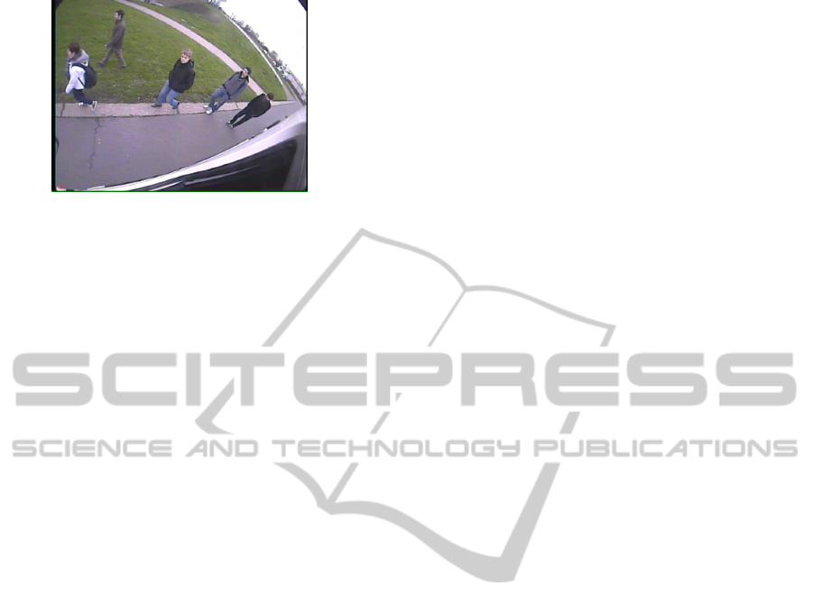
Figure 2: Example frame of our blind spot camera setup.
also bicyclists, mopeds, wheelchair users and children
are included. Besides the objects that need to be de-
tected, the nature of this specific problem introduces
another challenge: due to the position of the camera
(which is aimed at the blind spot zone), we have a
highly dynamical background. And since the camera
is moving, standard computer vision techniques like
adaptive background estimation or background sub-
traction, which can be computed very fast and would
largely facilitate the detection task, are not an option.
However, the biggest challenge is the hard real-time
constraint of this application combined with the need
for a high precision and recall rate.
In this paper we present part of such a complete
safety system: we developed a real-time robust multi-
pedestrian detector/tracker for real blind spot cam-
era images which maintains high accuracy. In the
future we plan to extend our system to multi-class.
As opposed to the classically used sliding window
approach, our algorithm is based on a warping win-
dow approach. In previous work we performed ini-
tial blind spot pedestrian detection experiments using
a standard camera, mounted on a standard car (Van
Beeck et al., 2011). Here, we present our warping
window approach to cope with the specific viewing
angle of a real blind spot camera mounted on a real
truck, and the distortion that this camera introduces.
An example frame of our blind spot camera setup is
displayed in figure 2. One clearly sees that standard
pedestrian detectors (discussed in the next section),
even if they were fast enough, cannot be used on
these images because they are developed for pedes-
trians that appear upright in the image. Using our
frameworkwe manage to robustly detect and track the
pedestrians while maintaining excellent speed perfor-
mance. This is briefly done as follows. Using our
warping window method, we can warp the regions
of interest in the image and use a standard pedes-
trian detector at only one specific scale, which is very
fast. We then integrate this approach in a tracking-by-
detection framework, and further speedup the algo-
rithm using temporal information to reduce the search
space. To meet the strict accuracy demands, we use a
pedestrian detector (Felzenszwalb et al., 2010) which
has very good accuracy at the cost of high computa-
tion time when it is used as is. Using our framework
this detector still achieves high accuracy but at real-
time performance (on our dataset we achieve an av-
erage frame rate of 10 fps). Since to our knowledge
no truck blind spot camera datasets are available in
the literature, we recorded our own real-life datasets
in which we simulated different dangerous blind spot
scenarios using a real truck. These images are used
to evaluate our algorithm regarding both to speed and
accuracy. The outline of this paper is as follows: sec-
tion 2 discusses related work on this topic. Section 3
describes our pedestrian tracking algorithm in detail.
In Section 4 we describe the datasets that we recorded
together with the result of our approach. We conclude
in section 5 with final remarks and future work.
2 RELATED WORK
A vast amount of literature concerning pedestrian de-
tection is available. In (Dalal and Triggs, 2005) the
authors propose the use of Histograms of Oriented
Gradients (HOG). This idea was further extended to a
multi part-based model in (Felzenszwalb et al., 2008).
Later these authors further optimized their detection
algorithm, and introduceda cascaded version (Felzen-
szwalb et al., 2010). All of the mentioned detectors
use a sliding window paradigm: across the entire im-
age one tries to find pedestrians at all possible lo-
cations and scales. This approach does not achieve
real-time performance at the moment. To overcome
this problem methods have been proposed that use
a detector cascade with a fast rejection of the false
detections (Viola and Jones, 2001), whereas others
methods use a branch and bound scheme (Lampert
et al., 2009). To avoid the need to fully construct the
scale-space pyramid Doll´ar et al. proposed a multi-
scale pedestrian detector (coined The fastest pedes-
trian detection in the west or FPDW) which uses fea-
ture responses computed at a specific scale to ap-
proximate features responses at scales nearby (Doll´ar
et al., 2010). Several comparative works on pedes-
trian trackers exist in the literature. In (Enzweiler
and Gavrila, 2009) a comparison is given between the
Dalal and Triggs model (HOG combined with a lin-
ear SVM classifier) with a wavelet-based AdaBoost
cascade. Their work shows a clear advantage of the
HOG-based approach at the cost of lower process-
ing speeds. In (Doll´ar et al., 2009) seven pedes-
trian detectors, all based on HOG or Haar features
trained with a boosting method or SVMs are com-
pared. They concluded that the HOG detectors per-
ICINCO2012-9thInternationalConferenceonInformaticsinControl,AutomationandRobotics
562
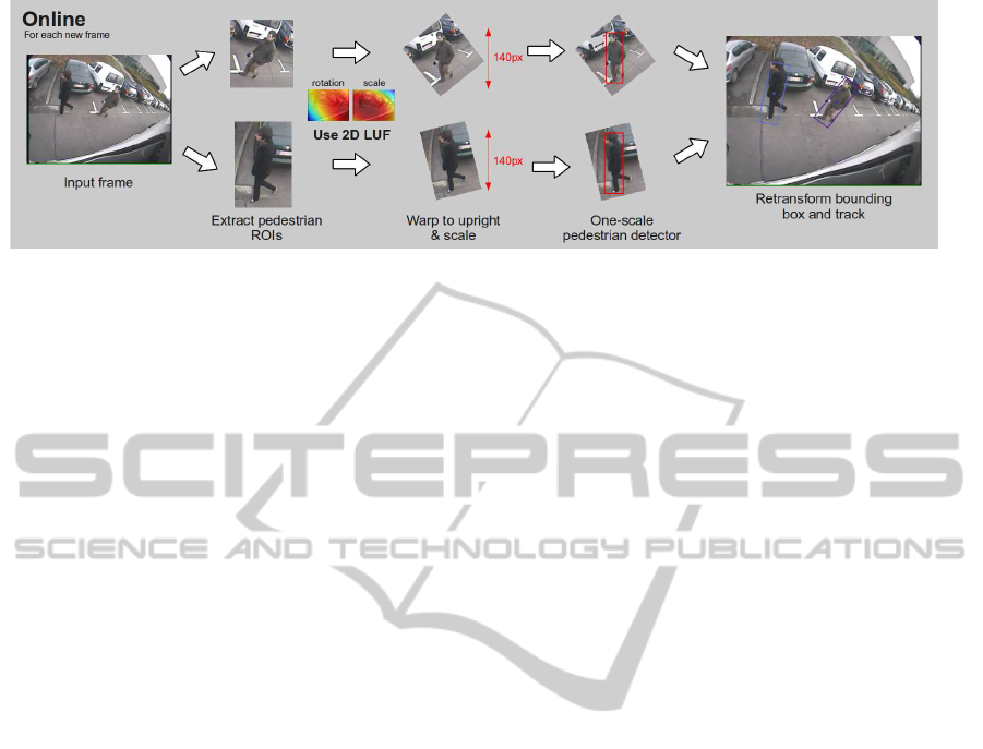
Figure 3: Our warping window approach. If the scale and rotation are known, we can warp the ROIs and use a standard
pedestrian detector at only one scale.
form best for unoccluded pedestrians over 80 pixels
high. A multifeature combination (HOG combined
with Haar features) outperforms HOG in more diffi-
cult situations at an evidently higher computational
cost. More recently, in (Doll´ar et al., 2011) the same
authors present an exhaustive evaluation of sixteen
state-of-the-art pedestrian detectors. Their evalua-
tion shows that part-based pedestrian detectors still
achieve the highest accuracy, while the FPDW is at
least one order of magnitude faster with only minor
loss of accuracy. These results were our motivation
to use the (Felzenszwalb et al., 2010) pedestrian de-
tector as a base detector in our framework. Regarding
pedestrian tracking algorithms, most of them rely on a
fixed camera, and use a form of background subtrac-
tion (Viola et al., 2005; Seitner and Hanbury, 2006).
As mentioned this cannot be used in our application,
since we have to work with moving camera images.
Due to the specific blind spot view, which is a back-
wards/sideways looking view, detecting and tracking
pedestrians is not a trivial task. Existing pedestrian
trackers on moving vehicles mostly use a forward-
looking camera (Ess et al., 2008), thereby reducing
the complexity of the scene. Often a stereo camera
setup is used, and the disparity characteristics are ex-
ploited (Gavrila and Munder, 2007). Since our goal
is to develop a system which is easily integrated into
existing blind spot camera systems we need to use a
monocular approach. We differ from all of the track-
ers mentioned above: we aim to develop a monocu-
lar multi-pedestriantracking system with field of view
towards the blind spot zone of the vehicle at real-time
performance, while maintaining high accuracy.
3 PEDESTRIAN TRACKING
ALGORITHM
Our warping window algorithm is mainly based on
the following observation. Looking at the blind spot
camera example frame in figure 2 one clearly notices
that, due to the specific position of the blind spot cam-
era and the wide angle lens, pedestrians appear ro-
tated and scaled. The crux of the matter is that the
amount of rotation and scaling is only dependent on
the position in the image. Thus, each pixel coordi-
nate x = [x, y] represents a specific scale and pedes-
trian rotation. If at each pixel coordinate the corre-
sponding rotation and scale is known, one can dra-
matically speedup pedestrian detection. Instead of a
classic full scale-space search we can warp the region
of interest, which is extracted based on the scale at
that pixel coordinate, to upright pedestrians on one
standard scale. This way we can use a standard pedes-
trian detector at only one scale, which is very fast. Be-
sides our application, this approach can easily be gen-
eralized to other applications where such wide-angle
distortion and/or non-standard camera viewpoints oc-
curs (e.g. surveillance applications). To get the rota-
tion and scale for each pixel coordinate a one-time
calibration step is needed. To enable robust track-
ing we integrate this warping window approach into
a tracking-by-detection framework. We use temporal
information to predict the next pedestrian positions,
eliminating the need for a full search over the entire
image. The next subsections each describe part of the
algorithm. First our warping window approach is de-
scribed in detail. We then give a quantitative motiva-
tion for our pedestrian detector choice and the size of
our standard scale in subsection 3.2. The last subsec-
tion explains how we integrate our warping window
approach into a robust tracking framework, and thus
describes how our complete algorithm works.
3.1 Warping Window Approach
The warping window approach is visualized in fig-
ure 3. Given input images as in figure 2, the pedestri-
ans appear rotated and scaled at different positions in
the image. If we assume that we have a flat ground-
plane, we know that the rotation and the scale of
these pedestrians only depends on their position in
AWarpingWindowApproachtoReal-timeVision-basedPedestrianDetectioninaTruck'sBlindSpotZone
563
the image. Thus if the scale s and rotation θ are
known for each position in the image (visualized in
the figure using the 2D lookup functions or LUF heat
map plots), we can warp the pedestrian ROIs (I) into
upright pedestrians at a standard scale (I
warp
), using
I
warp
= TI, with transformation matrix T:
T =
scosθ −ssinθ t
x
ssinθ scosθ t
y
0 0 1
(1)
A one-scale detector is used to detect the pedes-
trians, and the output coordinates of the bounding
boxes are retransformed into input image coordi-
nates. These coordinates are then fed into our tracking
framework, to determine the next pedestrian ROIs. To
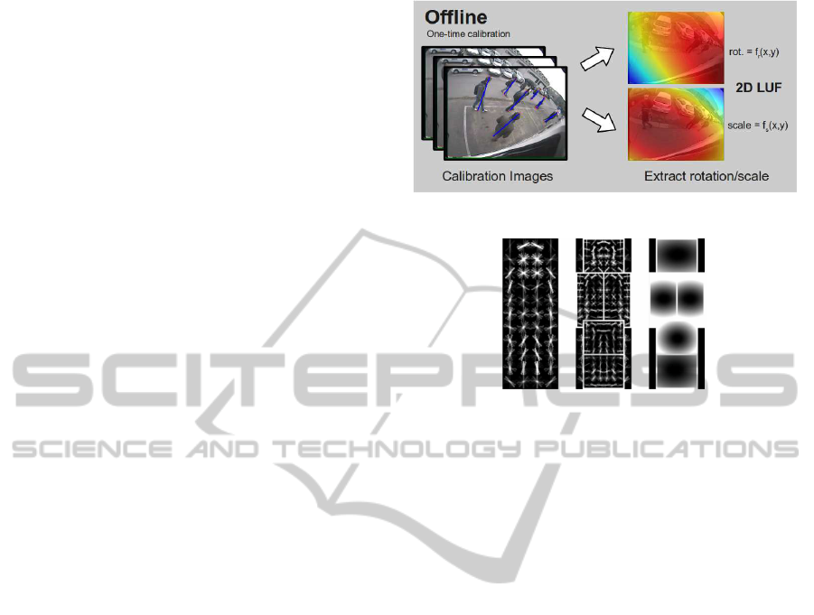
determine the scale and rotation for each pixel co-
ordinate, a one-time calibration step is needed (see
fig. 4). To achieve this, we manually labeled about
100 pedestrians in the calibration images homoge-
neously spread over the total image region. Each
pedestrian yields scale and rotation data at that po-
sition. Next we fitted a two-dimensional second
order polynomial function through the data points:
rotation = f
r
(x, y) and scale = f
s
(x, y) where:
f
i
(x, y) = A + Bx +Cy+ Dx
2
+ Exy+ Fy
2
(2)
Both functions are visualized as the two heat maps
in figure 4. These two functions effectively represent
a 2D lookup function, i.e. for each pixel coordinate
they give the rotation and scale of that pixel position.
If the camera position is adjusted, we need to perform
a recalibration. However, due to the robust camera
mounting on the truck this occurs only rarely.
Thus detecting pedestrians is composed of four
steps: extract the pedestrian ROI, calculate the scale
and rotation for that ROI, retransform to an upright
pedestrian with a standard height of 140 pixels and
use a pedestrian detector at only one scale. The choice
for this numberwill be argumented in the next subsec-
tion.
3.2 Pedestrian Detector
Since we only need to detect pedestrians at a standard
scale (140 pixels), our approach allows the use of a
detector with high accuracy which would otherwise
be too computationally expensive. Given the exten-
sive comparison results from (Enzweiler and Gavrila,
2009; Doll´ar et al., 2009; Doll´ar et al., 2011) that we
discussed in section 2, two pedestrian detectors are
applicable in our framework. Both the part-based de-
tector (Felzenszwalb et al., 2008; Felzenszwalb et al.,
2010) and the FPDW (Doll´ar et al., 2010) achieve
Figure 4: A one-time calibration step is needed.
Figure 5: The pedestrian HOG model. Root filter (L), Part
Filters (C), Prior estimate of position of the part filters (R).
high accuracy. The accuracy of the part-based mod-
els is slightly higher at the cost of a higher compu-
tation time due to scale-space pyramid construction.
Since no scale-space pyramid needs to be constructed
in our application, our choice evidently goes to the
part-based detector. Let us now briefly discuss how
this pedestrian detector works if used out-of-the-box.
The object that has to be detected is described using a
HOG model. The model consists of a root filter, rep-
resenting the pedestrian appearance, and a number of
smaller part filters, representing the head and limbs
of the pedestrian (see fig. 5). The position of each
of the parts are latent variables, which are optimized
during the detection. A first step is the construction of
a scale-space pyramid from the original image. This
is done by repeated smoothing and subsampling. For
each entry of this pyramid, a feature map is com-
puted, which is built using a variation of the HOG fea-
tures presented by Dalal and Triggs (Dalal and Triggs,
2005). For a specific scale one computes the response
of the root filter and the feature map, combined with
the response of the part filters and the feature map at
twice the resolution at that scale. The transformed re-
sponses of the part filters are then combined with the
response of the root filter to calculate a final score.
As a reference, if used out of the box on our im-
ages (640x480 resolution) this detector needs an av-
erage of 5.2 seconds per frame (evaluated on a Intel
Xeon Quad Core running at 3 GHz, all implementa-
tions are CPU-based only). If we reduce the number
of scales to only contain those needed in our applica-
tion, detection time decreases to about 850 ms. Later
ICINCO2012-9thInternationalConferenceonInformaticsinControl,AutomationandRobotics
564

1280x560 640x280 320x140 160x70 80x35
0
200
400
600
800
1000
1200
1400
1600
Resolution
Time (ms)
Detection Speed versus Resolution
Felzenszwalb reduced scales
Felzenszwalb one scale
Cascaded
Cascaded one scale
Figure 6: The calculation time for the different pedestrian
detector implementations.
the authors presented their cascaded version (Felzen-
szwalb et al., 2010). There, using a weak hypothesis
first, a fast rejection is possible while maintaining ac-
curacy. Using this detector, again out of the box and
only on the scales needed in our application, the de-
tection time on our images equals 340 ms.
We altered both the default and the cascaded part-
based pedestrian detector to a one-scale detector. In
figure 6 the average calculation times of the four dif-
ferent implementations, namely the part-based model
with reduced scales (further referenced as Felzen-
szwalb reduced scales), our one-scale implementa-
tion of this detector (referenced as Felzenszwalb one
scale), the cascaded version and our one-scale im-
plementation of the cascaded version. Needless to
say, the detection time strongly depends on the im-
age resolution. To generate figure 6, we used a high
resolution pedestrian image and cropped the image
to only contain the pedestrian. This image was then
subsampled to the indicated resolutions. Calculation
times are averaged on ten runs. Note that to obtain
a fair comparison we deliberately did not cache any
data. For example, the pedestrian model is completely
reloaded into memory on each run. We can clearly see
that decreasing the resolution drastically reduces the
calculation time for both the standard Felzenszwalb
as the cascaded detector. The calculation time of our
one-scale implementations does decrease with reso-
lution, but not nearly that fast. Since only one scale
is looked at, a double gain in speed is realized. The
scale-space pyramid does not need to be constructed,
and features only need to be calculated and evaluated
at one scale. In our warping window framework we
use the cascaded one-scale detector.
Reducing the resolution implies that the accuracy
significantly drops. Therefore we needed to deter-
mine the optimal trade-off point between the detec-
tion accuracy and the resolution to which we warp
our pedestrian images. To determine that optimal res-
170 160 150 140 130 120 110 100 90 80
0
0.1
0.2
0.3
0.4
0.5
0.6
0.7
0.8
0.9
1
Height of pedestrian (pixels)
Accuracy
Accuracy versus pedestrian resolution
Figure 7: The accuracy of our one-scale cascade detector
implementation in function of the pedestrian resolution.
olution we extracted about 1000 pedestrians from our
dataset, rescaled them to fixed resolutions and deter-
mined the accuracy of our one-scale cascaded detec-
tor for each resolution. These results are displayed in
figure 7. At higher pedestrian resolutions the accuracy
remains almost constant at around 94%.
When decreasing the pedestrian resolution the ac-
curacy starts to drop at approximately 135 pixels.
Based on these observations we chose to rescale our
pedestrians to a constant standard height of 140 pix-
els in our warping window approach. This results in
an average calculation time of 45 ms when using the
one-scale cascaded detector. If the model does not
need to be reloaded on each run, calculation time fur-
ther decreases to about 12 ms.
3.3 Tracking Framework
Our complete pedestrian tracking-by-detection algo-
rithm works as follows. We integrate our warp-
ing window approach into a reliable tracking-by-
detection framework. At positions where pedestri-
ans are expected to enter the blind spot zone in the
frame, standard search coordinates are defined, see
figure 9. Our warping window approach is used to de-
tect pedestrians at these search locations. If a pedes-
trian is detected, tracking starts. We use a linear
Kalman filter (Kalman, 1960) to estimate the next po-
sition of the pedestrian, based on a constant veloc-
ity model. Our experiments show that this assump-
tion holds and suffices for a robust detection. We de-
fine the state vector x
k
using the pixel position and
velocity of the centre of mass of each pedestrian:
x
k
=
x y v
x
v
y
T
. The Kalman filter imple-
ments the followingtime update equation ˆx
−
k
= Aˆx
k−1
.
Note that ˆx
−
k
refers to the a priori state estimate at
timestep k, while ˆx
k
refers to the a posterior state es-
timate at timestep k. The process matrix A equals:
AWarpingWindowApproachtoReal-timeVision-basedPedestrianDetectioninaTruck'sBlindSpotZone
565
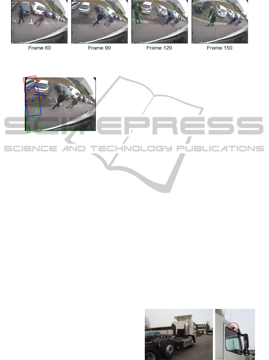
Figure 8: Example output of our tracking algorithm.
Figure 9: Example of three initial search coordinates, to-
gether with the search regions that they define.
A =
1 0 1 0
0 1 0 1
0 0 1 0
0 0 0 1
(3)
Using this motion model we predict the position
of the pedestrian in the next frame. Around the es-
timated pedestrian centroid a circular region with a
radius based on the scale at that coordinate, deter-
mined from the 2D scale LUF, is computed. In subse-
quent frames we use the estimated centroids and the
standard search coordinates as inputs for our warping
window approach. For each estimated centroid our
warping window approach warps this ROI and seeks
a new pedestrian detection. For every pedestrian that
is being tracked, the algorithm evaluates if a centroid
of such a new detection is found in its circular region.
If a matching centroid is found, that Kalman filter is
updated, and a new position is predicted. When mul-
tiple centroids are found, the nearest one is chosen.
If for a tracked pedestrian no new detection is found,
the Kalman filter is updated based on the estimated
position. This enables tracking of partially occluded
pedestrians or pedestrians where the HOG response
is temporarily lower (e.g. because of background ob-
jects). When no new matching detection is found for
multiple frames in a row (4 in our experiments), the
tracker is discarded. If a detection is found with no
previous tracked instance, tracking starts from there
on. This approach eliminates the need for a full frame
detection, thus limiting processing time. Figure 8
shows the output of our warping window tracking al-
gorithm on one video sequence.
4 EXPERIMENTS & RESULTS
Due to the specific viewing angle of the blind spot
camera no image datasets are available in the litera-
ture. Therefore we constructed such a dataset, con-
sisting of several simulated dangerous blind spot sce-
narios. This was done using a real blind spot cam-
era, mounted on a real truck. We used a commer-
cial blind spot camera (Orlaco CCC115
◦
), which out-
puts 640x480 images at 15 frames per seconds. It has
a wide-angle lens with a viewing angle of 115 de-
grees. Figure 10 indicates the position of the blind
spot camera on our truck. We recorded five different
scenarios. At each scenario the truck driver makes a
right turn, and the pedestrians react differently. For
example, in some of the scenario’s the truck driver
takes a right turn while stopping to let the pedestrians
cross the street, while in other scenario’s the pedes-
trians stand still at the very last moment while the
truck continues his turn. These simulations resulted
in a dataset of about 11000 frames. Our evaluation
hardware consists of an Intel Xeon Quad Core, which
runs at a clockspeed of 3 GHz. All implementations
are CPU-based, we do not use GPU implementations.
The algorithm is mainly implemented using Matlab,
while part of the pedestrian detector is implemented
in standard C-code. The image warping is imple-
mented in OpenCV, using mexopencv. As mentioned
in section 3, as a reference, when used out of the box
the Felzenszwalb pedestrian detector needs 5.2 sec-
onds for a full scale-space detection over an entire
frame. As our goal is to develop a real-time pedes-
trian tracker with high accuracy, we evaluated the al-
Figure 10: Our test truck (L) with the mounted blind spot
camera circled in red (R).
ICINCO2012-9thInternationalConferenceonInformaticsinControl,AutomationandRobotics
566

−20 −10 0 10 20 30 40 50 60
0
5
10
15
20
25
30
35
40
45
50
Pedestrian rotation (degrees)
Time (ms)
Detection Speed versus Rotation
Model Evaluation Time
Feature Calculation Time
Warping Time
Total Detection Time
Figure 11: Speed analysis of our warping window approach.
The blue line indicates the total calculation time per pedes-
trian, in function of the rotation.
gorithm with respect to both speed and accuracy. Our
results are presented in the next subsections.
4.1 Speed Analysis
For each tracked pedestrian we need to do a new de-
tection in the consequent frames. Thus if more pedes-
trians enter the frame, the total calculation time in-
creases. Figure 11 displays the detection time per
tracked pedestrian in function of the rotation. We split
up the total detection time in three separate steps: first
the image is warped in an upright fixed scale pedes-
trian image. Then our pedestrian detector calculates
the HOG features. The last step consists of the ac-
tual model evaluation, in which the image is given a
score based on the HOG model. The total detection
time increases if the rotation angle increases. Warp-
ing the window is computationally the least expensive
operation. It only slightly depends on the rotational
value, and maximally takes about 3 ms. The feature
calculation and the model evaluation take almost an
equal amount of time, and both increase with increas-
ing rotation. This is due to the fact that the total image
area increases with increasing rotation (see figure 12).
If no rotation is needed, both feature calculation and
model evaluation time take about 5 ms, resulting in a
total detection time of 12 ms. In the worst-case sce-
nario, occurring at a rotation of 52 degrees (the max-
Figure 12: Example one-scale pedestrian detector input im-
ages for different rotations.
Table 1: Speed Results as measured over our dataset.
best-case average worst-case
FPS 50.8 10.1 7.8
# pedestrians 0 3.1 5
imum rotation in our application), the detection time
increases to 35 ms. Thus if e.g. two pedestrians are
tracked, of which one at low rotation and one at high
rotation, detection time for these pedestrians requires
about 45 ms. If two standard search regions are in-
cluded at e.g. 15 ms each the total frame detection
time equals 72 ms. In that case the algorithm achieves
a frame rate of 14 frames per second. If multiple
pedestrians are detected, detection speed decreases.
Large groups of pedestrians are however easily no-
ticed by the truck driver and therefore do not pose
a real risk for accidents. Most blind spot accidents
occur when only a few (mostly only one) pedestrian
are in the blind spot zone. If only one pedestrian is
tracked our algorithm achieves a frame rate of more
than 20 frames per second. Table 1 shows the aver-
age, best-case and worst-case frame rate as evaluated
over our dataset, and gives the number of pedestrians
that were tracked while achieving these frame rates.
Since in our dataset on average more than 3 pedes-
trians were visible per frame, the average calculation
time given here is in fact an overestimation of the cal-
culation time for a real scenario.
4.2 Accuracy Analysis
The accuracy of our detector is displayed in the
precision-recall graph in figure 13. They are deter-
mined as: precision =
TP
TP+FP
and recall =
TP
TP+FN
.
For each pedestrian that our algorithm detects, we
look for the centroid of a labeled pedestrian in the cir-
cular region of the detection. If this it the case, the
detection is counted as a true positive. If no labeled
pedestrian is found, the detection is indicated as being
a false positive. If a labeled pedestrian is not detected,
this is indicated as being a false negative. Our test-
0 0.2 0.4 0.6 0.8 1
0
0.1
0.2
0.3
0.4
0.5
0.6
0.7
0.8
0.9
1
Recall
Precision
Precision vs Recall
Figure 13: A precision-recall graph of our warping window
tracking approach as evaluated over our dataset.
AWarpingWindowApproachtoReal-timeVision-basedPedestrianDetectioninaTruck'sBlindSpotZone
567

set consists of about 1000 pedestrians in very diverse
poses and movements. As can be seen in the figure
our algorithm achieves both high precision and recall
rates. At a recall rate of 94%, we still achieve a pre-
cision rate of 90%. This is due to the fact that using
our warping window approach, the specific scale at
each position is known. Therefore false positives are
minimized, while the pedestrian detection threshold
can be set very sensitive. This way difficult to detect
pedestrians can still be tracked. While very good, the
accuracy is not perfect yet. Our warping window ap-
proach sometimes fails to track pedestrians due to low
responses of the HOG filter, induced because only a
subtle intensity difference between the pedestrian and
the background occasionally occurs. A possible so-
lution for this is the inclusion of other features, e.g.
motion information.
5 CONCLUSIONS & FUTURE
WORK
We presented a multi pedestrian tracking framework
for a moving camera based on a warping window ap-
proach. We invented this warping window approach
to cope with the specific wide-angle induced by the
blind spot camera. However, this methodology is eas-
ily applicable to other object detection applications in
situations where such distortion occurs, e.g. caused
by non-standard camera viewpoints or specific lenses.
To evaluate our algorithms we recorded a representa-
tive real blind spot dataset. Experiments where per-
formed evaluating both the speed and accuracy of our
approach. Our algorithm achieves real-time perfor-
mance while still maintaining both high precision and
recall. In the future we plan to extend our track-
ing framework to allow tracking of other road users
besides pedestrians, starting with bicyclists. Prelim-
inary experiments show that the pedestrian detector
also performs well on bicyclists. We also plan to in-
vestigate if the inclusion of other information cues,
for example motion features extracted from optical
flow information, further increase the robustness of
our detector.
REFERENCES
Dalal, N. and Triggs, B. (2005). Histograms of oriented
gradients for human detection. In International Con-
ference on Computer Vision & Pattern Recognition,
volume 2, pages 886–893.
Doll´ar, P., Belongie, S., and Perona, P. (2010). The fastest
pedestrian detector in the west. In Proceedings of
the British Machine Vision Conference, pages 68.1–
68.11.
Doll´ar, P., Wojek, C., Schiele, B., and Perona, P. (2009).
Pedestrian detection: A benchmark. In Proceedings of
the IEEE Conference on Computer Vision and Pattern
Recognition.
Doll´ar, P., Wojek, C., Schiele, B., and Perona, P. (2011).
Pedestrian detection: An evaluation of the state of the
art. In IEEE Transactions on Pattern Analysis and
Machine Intelligence, volume 99.
Enzweiler, M. and Gavrila, D. M. (2009). Monocu-
lar pedestrian detection: Survey and experiments.
31(12):2179–2195.
Ess, A., Leibe, B., Schindler, K., and Gool, L. V. (2008). A
mobile vision system for robust multi-person tracking.
In Proceedings of the IEEE Conference on Computer
Vision and Pattern Recognition.
EU (22 february 2006). Commision of the european com-
munities, european road safety action programme:
mid-term review.
Felzenszwalb, P., Girschick, R., and McAllester, D. (2010).
Cascade object detection with deformable part mod-
els. In Proceedings of the IEEE Conference on Com-
puter Vision and Pattern Recognition.
Felzenszwalb, P., McAllester, D., and Ramanan, D. (2008).
A discriminatively trained, multiscale, deformable
part model. In Proceedings of the IEEE Conference
on Computer Vision and Pattern Recognition.
Gavrila, D. and Munder, S. (2007). Multi-cue pedestrian
detection and tracking from a moving vehicle. In In-
ternational Journal of Computer Vision, volume 73,
pages 41–59.
Kalman, R. (1960). A new approach to linear filtering
and prediction problems. In Transaction of the ASME
Journal of Basic Engineering, volume 82, pages 35–
45.
Lampert, C., Blaschko, M., and Hoffmann, T. (2009). Effi-
cient subwindow search: A branch and bound frame-
work for object localization. In IEEE Transactions
on Pattern Analysis and Machine Intelligence, vol-
ume 31, pages 2129–2142.
Martensen, H. (2009). Themarapport vracht-
wagenongevallen 2000 - 2007 (BIVV).
Seitner, F. and Hanbury, A. (2006). Fast pedestrian tracking
based on spatial features and colour. In Proceedings
of the 11th Computer Vision Winter Workshop, pages
105–110.
Van Beeck, K., Goedem´e, T., and Tuytelaars, T. (2011). To-
wards an automatic blind spot camera: Robust real-
time pedestrian tracking from a moving camera. In
Proceedings of the twelfth IAPR Conference on Ma-
chine Vision Applications, pages pp. 528–531.
Viola, P. and Jones, M. (2001). Rapid object detection using
a boosted cascade of simple features. In Proceedings
of the IEEE Conference on Computer Vision and Pat-
tern Recognition, pages 511–518.
Viola, P., Jones, M., and Snow, D. (2005). Detecting pedes-
trians using patterns of motion and appearance. In In-
ternational Journal of Computer Vision, volume 63,
pages 153–161.
ICINCO2012-9thInternationalConferenceonInformaticsinControl,AutomationandRobotics
568
