
A Model-driven Approach to Build HLA-based Distributed Simulations
from SysML Models
Paolo Bocciarelli, Andrea D’Ambrogio and Gabriele Fabiani
Dept. of Enterprise Engineering, University of Rome ”Tor Vergata”, Rome, Italy
Keywords:
SysML, HLA, Simulation, Model-driven, QVT.
Abstract:
The analysis and design of complex systems, which very often are composed of several sub-systems, takes
advantages by the use of distributed simulation techniques. Unfortunately, the development of distributed
simulation systems requires a significant expertise and a considerable effort for the inherent complexity of
available standards, such as HLA. This paper introduces a model-driven approach to support the automated
generation of HLA-based distributed simulations starting from system descriptions specified by use of SysML
(Systems Modeling Language), the UML-based general purpose modeling language for systems engineering.
The proposed approach is founded on the use of model transformation techniques and relies on standards
introduced by the Model Driven Architecture (MDA). The method exploits several UML models that embody
the details required to support two transformations that automatically map the source SysML model into a
HLA-specific model and then use the latter to generate the Java/HLA source code. To this purpose, this paper
also introduces two UML profiles, used to annotate UML diagrams in order both to represent HLA-based
details and to support the automated generation of the HLA-based simulation code.
1 INTRODUCTION
The analysis and design of systems in several appli-
cation domains (e.g., aerospace, defence, economics,
software, medical, etc.) is often based on the use of
simulation techniques. Simulation-based approaches
allow to analyze a system at design time, in order to
assess whether or not it accomplishes both functional
and performance requirements, whether or not it
satisfies constraints and, ultimately, to cut or reduce
the cost of experimental prototypes. Simulation
execution may be carried out by use of either a local
or a distributed approach.
Unlike local simulation, whose execution involves
a single host that includes all the resources needed
to complete its execution, a distributed simulation
(DS) approach involves a set of distributed hosts
interconnected by a local or geographical network
infrastructure (Fujimoto, 2001). DS is mainly used
to achieve scalability, aggregation and reusability
(D’Ambrogio et al., 2011a).
The simulation of modern and complex systems,
which very often are composed of several sub-
systems, requires computational resources that might
not be available on a single host. In this respect, DS
is often used to enact a scalable way to simulate a co-
mplex system by partitioning the overall simulation
into a set of simulation components, each executed
onto an independent host (Fujimoto, 1999).
Nevertheless, the use of DS-based approaches is
often limited by the non-negligible effort and the
significant skills that are required to make use of
DS frameworks and environments, such as the HLA
(High Level Architecture) framework and its related
implementation technologies.
To overcome such limitations, this work proposes
a method to support the automated generation of
HLA-based distributed simulations starting from
system descriptions specified by use of SysML (Sys-
tems Modeling Language), the UML-based general
purpose modeling language for systems engineering
(OMG, 2010).
The proposed method is carried out according
to principles and standards introduced in the model-
driven engineering field and is specifically founded
on the Model Driven Architecture (MDA), the
Object Management Group’s incarnation of model-
driven engineering principles (OMG, 2003). Such a
model-driven method makes use of model-to-model
and model-to-text transformations that have been
implemented by use of QVT (Query/View/Transfor-
mation) (OMG, 2008a) and MOFM2T (MOF Model
49
Bocciarelli P., D’Ambrogio A. and Fabiani G..
A Model-driven Approach to Build HLA-based Distributed Simulations from SysML Models.
DOI: 10.5220/0004059900490060
In Proceedings of the 2nd International Conference on Simulation and Modeling Methodologies, Technologies and Applications (SIMULTECH-2012),
pages 49-60
ISBN: 978-989-8565-20-4
Copyright
c
2012 SCITEPRESS (Science and Technology Publications, Lda.)

to Text Transformation Language) (OMG, 2008b),
respectively. The availability of such automated
transformations allows software engineers to derive
the executable HLA-based simulation code with no
extra effort and without being required to own specific
skills of DS standards, as shown by use of an example
application.
The proposed method includes two main steps:
• A model-to-model transformation step, to obtain
a model of the HLA-based distributed simulation,
starting from the system specification;
• A model-to-text transformation step, that takes
as input the simulation model and yields as
output the code that implements the HLA- based
distributed simulation.
The method exploits several UML models that
are created during the development of a distributed
simulation. Each model represents the system from
a specific point of view and at a given level of
abstraction. UML models are thus used both to
represent the system under a certain perspective
and also to embody the details required to support
the model transformations upon which the proposed
method has been built.
To this purpose, this paper also introduces
two UML profiles, or UML standard extension
mechanisms. The first one, named SysML4HLA
profile, is used to annotate a SysML-based system
specification to support the automated generation of
the HLA-based distributed simulation. The second
one, named HLA profile, is used to annotate an
UML diagram in order to represent HLA-based
implementation details.
The rest of this work is organized as follows:
Section 2 reviews relevant contributions which deal
with the topics addressed in this paper. Section 3
briefly introduces HLA and presents the proposed
HLA profile. Section 4 outlines the SysML notation
and introduces the SysML4HLA profile. Section 5
illustrates the proposed model-driven method that ex-
ploits the HLAProfile and the SysML4HLAProfile to
support the development of a HLA-based distributed
simulation. Finally, Section 6 illustrates an example
application of the proposed method.
2 RELATED WORK
This section reviews the existing literature dealing
with both the use of SysML in Modeling & Simulation
(M&S) domain and the modeling/development of
HLA-based distributed simulation systems.
As regards the use of SysML in the M&S context,
to the best of our knowledge, no contributions can
be found that specifically address the topic faced
in this paper: the generation of Java/HLA code,
starting from SysML specifications. Nevertheless,
several contributions are available that propose the
use of SysML as a notation suitable not only for
defining systems specification but also for supporting
the system simulation, such as (Weyprecht and Rose,
2011; Peak et al., 2007; Paredis and Johnson, 2008).
In (Weyprecht and Rose, 2011) a simulation core,
implemented by use of fUML, has been proposed.
This paper advocates SysML as a standardized
simulation language, and model-driven techniques are
introduced to generate the code of a simulation soft-
ware, starting from SysML behavioral models, such
as Activity Diagram. In such a paper the adoption
of a model-driven paradigm is limited to the use of
the Eclipse Modeling Framework (EMF), specifically
the Java Emitter Templates (JET), to generate a
basic source code skeleton for each needed class.
Moreover, from the implementation point of view,
the paper only describes a prototypal implementation
of the simulation core. The implementation of a
complete simulation solution is planned as a future
work.
In (Peak et al., 2007) SysML is used as a notation
to support the simulation-based design (SBD) of
systems. By presenting several examples, such papers
show how SysML is able to capture engineering
knowledge needed to derive executable parametric
models.
In (Paredis and Johnson, 2008) the use of SysML
is proposed to support the system simulation. More
specifically, such a paper introduces the use of a graph
transformation approach to accomplish an automated
transformation between SysML and domain-specific
languages.
Differently from the above-mentioned contribu-
tions, this paper describes a model-driven method
to generate a Java/HLA-based implementation of
a distributed simulation software, starting from a
SysML specification.
As regards the representation of distributed
simulation systems, a large effort has been spent in
defining UML profiles for modeling HLA federations,
such as in (Topc¸u and O
ˇ
guzt
¨
uz
¨
un, 2000; Topc¸u
et al., 2003; Zhu et al., 2008). Similarly to such
contributions, this paper proposes an UML profile to
model a HLA-based simulation system that has been
partially based on the HLA Object Model Template
(OMT) (IEEE, 2000c). Nevertheless, this paper
goes far beyond and also takes into consideration the
HLA metamodel proposed in (Topc¸u et al., 2008), in
SIMULTECH2012-2ndInternationalConferenceonSimulationandModelingMethodologies,Technologiesand
Applications
50

order to improve the expressiveness of the proposed
profile. Moreover, it should be underlined that this
paper contribution is not limited to an UML extension
for modeling an HLA federation. This work also
proposes a model-driven method to generate the
implementation of a distributed simulation software,
starting from the SysML specification of the system
under study.
As regards the issue of implementing (or sup-
porting the implementation of) simulation systems,
several contributions can be found in literature that
apply a model-driven paradigm in the modeling and
simulation domain, such as (D’Ambrogio et al.,
2011b; Tolk and Muguira, 2004; Jimenez et al., 2006;
Haouzi, 2006)
In (D’Ambrogio et al., 2011b) a method to
generate Java/HLA-based implementation of a dis-
tributed simulation software, starting from a UML
representation of the system, has been proposed. On
the one hand, such a contribution constitutes a starting
point for this work, as the two papers share the
same objective (e.g., the automated generation of the
simulation implementation) and the adopted approach
(e.g., the model-driven paradigm). One the other
hand, this work extends the previous contribution in
several ways. The proposed model-driven method
is applied to the systems engineering domain thus,
in this paper case, the model transformations are
driven by the SysML representation of the system
under study. Moreover, this paper gives a more
extensive description regarding the adopted UML
profiles and both the model-to-model and model-
to-text transformations that constitute the method
implementation, as well.
In (Tolk and Muguira, 2004) a model-driven
approach is proposed in the M&S application domain.
Specifically, such a contribution proposes the creation
of a specific domain for Modeling and Simulation
(M&S) within MDA. Differently, this paper adopts
MDA techniques to the production of simulation
systems treated as general-purpose software systems.
This means that, in case of the system under study
is a software system, the same approach can be
adopted to eventually generate both the operational
system and the simulation system from the same
model specification. Moreover, the implementation
of the proposed method is not complete in terms of
both MDA compliance and software. Differently,
this paper approach implements a MDA compliant
process by introducing two UML profiles and a
set of model model-to-model and model-to-text
transformations for generating the simulation code
from a SysML model specification.
In (Jimenez et al., 2006) a MDA-based develop-
ment of HLA simulation systems is also proposed.
Such a contribution is limited to the definition of an
initial UML profile for HLA and, differently from
the contribution proposed in this paper, does not take
into consideration the application of the profile for the
implementation of the simulation system.
Finally, in (Haouzi, 2006) the main concepts
behind the application of MDA techniques to the
development of HLA systems are outlined. Such
a contribution is limited to a theoretical discussion
about the use of MDA-based techniques in HLA
domain. Differently, this work proposes a model-
driven approach to reduce the gap between the model
specification and the distributed system implementa-
tion. An example application is also discussed, in
order to show how the application of the proposed
method allows to reduce the simulation development
effort by automating the production of Java/HLA
code from an initial UML-based system specification.
3 HIGH LEVEL ARCHITECTURE
(HLA)
The High Level Architecture (HLA) is an IEEE
standard (IEEE, 2000b; IEEE, 2000d; IEEE, 2000c;
IEEE, 2000a; IEEE, 2007) that provides a general
framework for distributed simulation. The standard
promotes interoperability and reusability of simula-
tion components in different contexts. The standard is
based on the following concepts (Kuhl et al., 1999):
• Federate: a simulation program that represents
the basic element in HLA;
• Federation: a distributed simulation execution
composed of a set of federates;
• Run Time Infrastructure (RTI): a simulation-
oriented middleware consisting of a local com-
ponent (i.e., RTI Local), which resides on the
federate sites, and an executive component (i.e.,
RTI Executive), which is centralized.
• RTI Ambassador and Federate Ambassador: the
interfaces that handle the communications among
the federates and the RTI.
The major improvement introduced by HLA
standard is an API that aims to ease the development
of DS systems. Unfortunately, HLA still suffers
from three main drawbacks: (i) the complexity of the
API, (ii) the strictly distributed orientation of the API
and (iii) the absence of a standard communication
protocol between RTI Local and RTI Executive
(D’Ambrogio et al., 2011a).
As stated, this paper aims to propose a method
to support the code generation of a distributed
AModel-drivenApproachtoBuildHLA-basedDistributedSimulationsfromSysMLModels
51
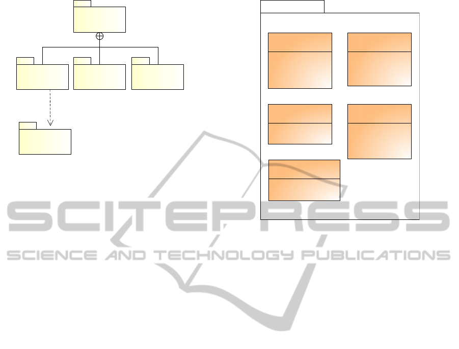
HLAProfile
BMMOMTKernel HSMM
HLADataTypes
«import»
Figure 1: Package structure of the UML profile for HLA.
simulation software. The first step consists of the
definition of an UML profile that extends UML in
order to represent a HLA-based simulation model. To
this respect, the next section presents the proposed
HLA profile.
3.1 HLA Profile
The proposed UML profile for HLA (briefly denoted
as HLAProfile) has been defined in order to model
concepts, domain elements and relationships defined
by the HLA metamodel (Topc¸u et al., 2008). For the
sake of brevity, the structure of such a metamodel is
not discussed in this work; a complete description
of the HLA metamodel can be found in (Topc¸u
et al., 2008). The HLAProfile includes several
stereotypes. In order to manage its complexity it
has been organized in several packages, as shown in
Figure 1.
3.1.1 HLADatatypes Package
This package includes the datatypes of the several
attributes used to specify the stereotypes included
in the OMTKernel package. Its structure is shown
in Figure 2. This package contains the following
enumerated types:
• PSKind: specifies the publish/subscribe capabil-
ities of a federate. It can assume the following
values: Publish, Subscribe, PublishSubscribe or
Neither;
• UpdateKind: specifies the policy for updating an
instance of a class attribute. It can assume the
following values: Static, Periodic or Conditional;
• DAKind: specifies whether ownership of an
instance of a class attribute can be released or
acquired. It can assume the following values:
Divest, Acquire, DivestAcquire or NoTransfer;
HLADataTypes
«enumeration»
DAKind
NoTransfer
DivestAcquire
Acquire
Divest
«enumeration»
OrderKind
Receive
Timestamp
«enumeration»
PSKind
Publish
Subscribe
PublishSubscribe
Neither
«enumeration»
UpdateKind
Static
Periodic
Conditional
NA
«enumeration»
TransportationKind
HLAReliable
HLABestEffort
Figure 2: HLADatatypes package structure.
• TransportationKind: specifies the transporta-
tion type. It can assume the following values:
HLAreliable or HLAbesteffort;
• OrderKind: specifies the order of delivery.
It can assume the following values: Receive,
TimeStamp.
3.1.2 OMTKernel Package
This package includes the stereotypes defined in the
HLA OMT specification. The provided stereotypes
and the related associations are shown in Figure 3.
• Federate: represents a federate within a federa-
tion. Extends the UML Component metaclass;
• ObjectClass: identifies an Object Class. Extends
the UML Class metaclass;
• InteractionClass: represents an interaction.
Extends the UML Component metaclass and is
specified by the following tagged values:
– Dimension: represents the association of a class
attribute with a set of dimensions;
– Transportation: specifies the transportation
type to be used;
– OrderKind. specifies the order of delivery.
• HLADimension: represents a specific dimension
for an attribute of an ObjectClass or an Interac-
tionClass. Extends the UML Class metaclass and
is specified by the following tagged values:
– DataType: identifies the datatype for the
federate view of the dimension;
SIMULTECH2012-2ndInternationalConferenceonSimulationandModelingMethodologies,Technologiesand
Applications
52
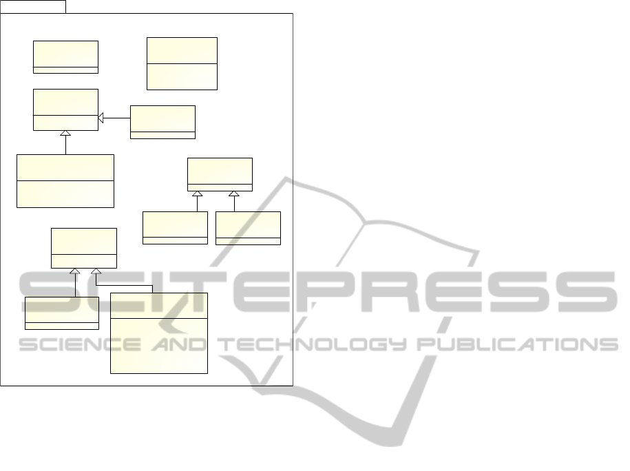
OMTKernel
«stereotype»
federate
[Component]
«stereotype»
hlaClass
[Class]
- sharing: PSKind
«stereotype»
objectClass
[Class]
«stereotype»
interactionClass
[Class]
- dimension: String
- transportation: TransportationKind
- order: OrderKind
«stereotype»
hlaDimension
[Class]
- dataType: String
- upperBound: Integer
- unspecifedValue: String
«stereotype»
hlaProperty
[Property]
- dataType: String
«stereotype»
interactionParameter
[Property]
«stereotype»
objectAttribute
[Property]
- updateType: UpdateKind
- updateCondition: String
- ownership: DAKind
- sharing: PSKind
- transportation: TransportationKind
- order: OrderKind
«stereotype»
hlaAssociation
[Association]
«stereotype»
subscribe
[Association]
«stereotype»
publish
[Association]
Figure 3: OMTKernel package structure.
– UpperBound: specifies the upper bound that the
federation requirements allow;
– UnspecifiedValue: specifies a default range.
• HLAProperty: Defines the abstract
concept of properties that is specialized by
ObjectAttribute and InteractionParameter
stereotypes. Extends the UML Component
metaclass and is specified by the following
tagged value:
– DataType: datatype of attributes or parameters.
• ObjectAttribute: represents an object class
attribute. Extends the UML Property metaclass
and is specified by the following tagged values:
– UpdateType: specifies the policy for updating
an attribute;
– Ownership: indicates whether ownership of an
instance of a class attribute can be released or
acquired;
– Sharing: specifies the publish/subscribe capa-
bilities of a federate with respect to an attribute;
– Dimension: represents the association of a class
attribute with a set of dimensions;
– Transportation: specify the type of transporta-
tion;
– Order: specify the order of delivery;
• InteractionParameter: represents an interaction
class attribute. Extends the UML Property
metaclass.
• HLAClass: represents an abstraction of object
class and interaction class. Extends the UML
Class metaclass and is specified by the following
tagged values:
– Sharing: represents the information on publica-
tion and subscription capabilities;
• HLAAssociation: represents an abstraction that
is specialized by publish and subscribe stereo-
types. Extends the UML Association metaclass;
• Publish: represents the association between a
Federate and a published element. Extends the
UML Association metaclass;
• Subscribe: represents the association between a
Federate and a subscribed element. Extends the
UML Association metaclass.
3.1.3 HSMM Package
This package includes the stereotypes derived by the
HLA service and HLA method concepts, according
to the HLA Services Metamodel. Such stereotypes,
summarized in Table 1, are defined to model the
events defined in the HLA Behavioral Metamodel.
3.1.4 BMM Package
This package includes the stereotypes derived by the
HLA Behavioral Metamodel that provides the UML
extensions needed to model the observable behavior
of the federation, as summarized in Table 2.
4 SYSTEM MODELING
LANGUAGE AND HLA
SysML (System Modeling Language) (OMG, 2010)
is an UML profile provided by OMG for mod-
eling complex systems in the systems engineering
domain. As discussed in Section 1, simulation-
based techniques should be introduced during the
development of complex systems, in order to conduct
an early assessment of the system behavior, and thus
to determine whether or not the system meets the user
requirements.
Unfortunately, the development of distributed
simulations starting from SysML specifications re-
quires a non-negligible effort, and SysML does
not provide any information that can support such
development process.
AModel-drivenApproachtoBuildHLA-basedDistributedSimulationsfromSysMLModels
53
Table 1: HSMM stereotypes.
Stereotype Extension Description
hlaService Interface Defines an interface implemented by components acting the role of federate
hlaMethod Operation Defines an operation provided by an interface
Table 2: MSC stereotypes.
Stereotype Extension Description
action Message Identifies a request for executing an operation by a federate
initialization Message Identifies messages exchanged to setup the distributed simulation infrastructure
message Message Identifies a communications between two federates
Table 3: SysML4HLA stereotypes.
Stereotype Extension
federate Block (UML Class)
objectClass Block (UML Class)
interactionClass Block (UML Class)
To this respect, this paper proposes an UML
profile for extending SysML, in order to enrich
a SysML diagram with information needed to
support the automated generation of the HLA-based
distributed simulation implementation.
4.1 SysML4HLA Profile
This section introduces the SysML4HLA profile,
an UML profile specifically introduced to annotate
a SysML model in order to make such speci-
fication suitable to drive a model-driven method
for generating the HLA code that implements the
distributed distributed simulation. SysML4HLA
provide stereotypes that extend the block element of
SysML, which in turn is an extension of UML class
metaclass. These stereotypes have been introduced to
represent the basic elements of an HLA simulation:
federates, objectClasses and interactionClasses. The
proposed SysML4HLA profile is shown in Table 3.
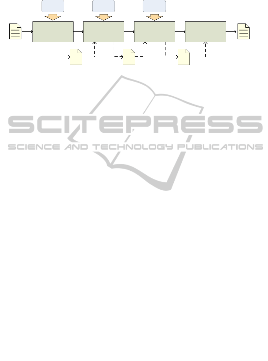
5 MODEL-DRIVEN METHOD TO
SUPPORT A HLA-BASED
DISTRIBUTED SIMULATION
This section illustrates how the UML profiles
introduced in sections 3.1 and 4.1 are used to generate
the Java/HLA code that implements the distributed
simulation software. The proposed method, shown
in Figure 4, is founded on model-driven principles
and standards and exploits the SysML4HLAProfile
and the HLAProfile to enact the automated code
generation of the HLA-based simulator.
At the first step, the system under study (and that
is going to be simulated) is initially specified in terms
of UML diagrams annotated with the SysML profile
(e.g., block definition diagrams, sequence diagrams,
etc.). According to the model-driven terminology
(OMG, 2003), such a model constitutes the platform
independent model (PIM) of the system. At this step,
the system engineer in charge of producing the system
model, is not concerned with any detail regarding the
simulation model. The focus is on the specification
of an UML-based system design model, starting from
the system requirements.
At the second step, the SysML4HLAProfile is
used to annotate the PIM in order to enrich such a
model with information needed to derive the HLA
simulation model. Specifically, the HLA profile
allows to specify both how the system has to be
partitioned in terms of federation/federates and how
system model elements have to be mapped to HLA
model elements such as object class and interaction
class.
The third step takes as input the marked PIM and
the HLA profile, and carry out the SysML-to-HLA
model-to-model transformation, in order to automat-
ically obtain an UML model, annotated with the
stereotypes provided by the HLA profile, which
represents the HLA-oriented simulation model. The
latter, according to the model-driven paradigm,
constitutes the platform specific model (PSM).
Finally, at the fourth step, the Java/HLA-based
code of the simulation model is generated by use of
the HLA-to-Code model-to-text transformation.This
step requires the choice of a specific HLA implemen-
tation (e.g., Pitch, Portico, etc.) that provides the
HLA services in a given programming language (e.g.,
Java, C++, etc.)
1
.
1
it should be noted the implementation of HLA-to-Code
transformation provided in this work makes use of Portico
and Java. Nevertheless, the model-driven approach at the
basis of the proposed method allows to use different HLA
implementations or programming languages. All such cases
can be easily dealt with by revising the specification of the
SIMULTECH2012-2ndInternationalConferenceonSimulationandModelingMethodologies,Technologiesand
Applications
54
System
Specification
SysML
Profile
Federation
Specification
Model-to-Model
Transformation
SysML4HL
Profile
HLA
Profile
Model-to-Text
Transformation
UML
SysML profile
marked
PIM
UML
SysML profile
+
SysML4HLA profile
marked
PIM
Java/HLA code
UML
HLAprofile
PSM
PIM
System
Requirements
Figure 4: Model-driven method to automate the generation of Java/HLA code.
The following subsections describe the SysML-
to-HLA transformation and the HLA-to-Code trans-
formation, respectively.
5.1 SysML-to-HLA Transformation
The SysML-to-HLA model transformation takes as
input a UML model representing the system under
study and yields as output an UML model that
specifies the HLA-based distributed simulation. The
input model is annotated with stereotypes provided
by both SysML and SysML4HLA profiles, while the
output model makes use of the HLA profile.
Specifically, the source model consists of the
following SysML diagrams:
• a Block Definition Diagram, that defines the static
structure of the system to be developed in terms
of its physical components;
• a set of Sequence diagrams, that show the
interactions among system components.
The target model is specified by the following
UML diagrams:
• Structural model, constituted by a component
diagram, that shows the partition of the simulation
model in terms of federates;
• Behavioral model, constituted by a set of se-
quence diagrams that show the interactions among
the federates and the RTI;
• Publish/Subscribe diagram, constituted by a
second component diagram, that shows how
federates publish or subscribe HLA resources
(i.e., object classes and interaction classes).
As stated in Section 1, the model transformation
has been implemented by use of QVT-Operational
mapping language (OMG, 2008a), which is provided
by the Object Management Group (OMG) as the
HLA-to-Code model-to-text transformation.
standard language for specifying model transforma-
tions that can be executed by available transformation
engines (Eclipse, 2010; IKV++, 2008). The following
subsections 5.1.1, 5.1.2 and 5.1.3 specify, by use
of natural language, the mapping rules defined to
generate the structural model, the behavioral model
and the Publish/Subscribe diagram, respectively.
5.1.1 Structural Model
Rule 1: Depending on its SysML4HLA stereotype
(i.e., the role played in the source model), a block
element in the SysML diagram can be mapped to a
federate element, an objectclass element or an
interaction class element in the target model.
According to such rule, the main block element
in the block definition diagram stereotyped as
<<Federate>>, represents a HLA federate and is thus
mapped to an UML component element, stereotyped
as <<Federate>>. Other blocks element, stereotyped
as <<Objectclass>> or <<InteractionClass>>
and connected by a composition relationship with the
block element represent federate elements, which
are mapped to UML class elements, stereotyped
as <<Objectclass>> or <<InteractionClass>>,
respectively, and nested to the federate component.
Rule 2: Attributes of classes representing
federate elements in the source model are mapped
to class attributes in the target model. Such
attributes, associated to the related class in the
target model generated according to rule 1,
are stereotyped as <<objectAttribute>> and
<<interactionParameter>>.
Rule 3: Each UML class element in the source
model is mapped to an interface element in the
target model, stereotyped as <<hlaService>>. The
related class methods in the target model are mapped
to corresponding methods in the source model,
stereotyped as <<hlaMethod>>.
Rule 4: Federate component in the target model
AModel-drivenApproachtoBuildHLA-basedDistributedSimulationsfromSysMLModels
55

generated according to rule 1 is associated to the
interfaces generated according to rule 5 by an
implements association.
Table 4 summarizes the mapping rules.
5.1.2 Behavioral Model
The sequence diagrams in the source model specify
the interactions between model elements represent-
ing federates (i.e., block elements stereotyped as
<<federate>>) and/or model elements representing
federate elements (i.e., block elements stereotyped
as <<ObjectClass>> or <<InteractionClass>>).
The behavioral view of the target model is obtained
according to the following rules.
Rule 1: Each UML sequence diagram in the
source model is mapped to a sequence diagram in the
target model. Such diagrams specify the behavioral
view of the target model.
Rule 2: In order to represent interactions between
federates and the HLA RTI, each sequence diagram
contains an UML component named RTI.
Rule 3: Each sequence diagram in the target
model represents the behavior of a federate interact-
ing with its component and/or other federates. The
diagram must contains the following messages:
• a self message named createRTIAmbassador,
stereotyped as <<initialization>>;
• a message exchanged between federate and RTI,
named createFederationExecution, stereotyped as
<<initialization>>;
• a self message named createFederateAmbas-
sador, stereotyped as <<initialization>>;
• a message exchanged between federate and
RTI, named enableTimeRegulation, stereotyped
as <<initialization>>;
• a message exchanged between federate and
RTI, named joinFederation, stereotyped as
<<initialization>>;
• main flow according to rules 3 and 4;
• a message exchanged between federate and
RTI, named leaveFederation, stereotyped as
<<message>> ;
Rule 4: messages included in the source
sequence diagram exchanged between a federate
and one of its component (i.e., an element stereo-
typed as <<federate>> and an element stereotyped
as <<ObjectClass>> or <<InteractionClass>>,
respectively) are mapped to self messages of the
federate, stereotyped as <<action>>.
Rule 5: messages included in the source
sequence diagram exchanged between two federates
are mapped to messages between federate and RTI
(and vice-versa). Such messages are stereotyped as
<<messages>>.
5.1.3 Publish/Subscribe Diagram
The publish/subscribe diagram is generated starting
from the block definition diagram, according to the
following rules:
Rule 1: Blocks in the source model are mapped to
UML classes and components, according to the same
rule 1 specfied in 5.1.1;
Rule 2: Each composition association be-
tween a block A stereoyped as <<federate>> and
a block B stereotyped as <<objectclass>> or
<<interactionclass>> is mapped to two different
associations between the corresponding elements
C and D in the target model, stereotyped as
<<publish>> or <<subscribe>>, respectively. C
and D are generated from A and B by applying rule
1.
Rule 3: Each composition association be-
tween a block A stereoyped as <<federate>>
and a block B stereotyped as <<objectclass>>
or <<interactionclass>>, where a composition
association between A and B does not exist, is
mapped to an association between the corresponding
elements C and D in the target model, stereotyped as
<<subscribe>>. C and D are generated from A and
B by applying rule 1.
Rule 4: Each composition association
between blocks A and B, both stereotyped as
<<objectclass>> or <<interactionclass>>,
where A and B do not share a composition
association with the same block C, is mapped to
an association between the corresponding elements
D and E in the target model, stereotyped as
<<subscribe>>. D and E are generated from C and
B by applying rule 1.
Figure 5 summarizes the above-mentioned map-
ping rules.
5.2 HLA-to-Code Transformation
The HLA-to-Code model-to-text transformation takes
as input an UML model representing the HLA-based
simulation system and yields as output the code that
constitutes its implementation.
The code generation makes use of Portico
(Portico, 2010), an open source implementation of the
HLA RTI, and Java as the language for implementing
federates and ambassadors. The model-to-text
transformation has been implemented by use of
Acceleo (Eclipse, 2011), the model-driven Eclipse
plugin for code generation.
SIMULTECH2012-2ndInternationalConferenceonSimulationandModelingMethodologies,Technologiesand
Applications
56
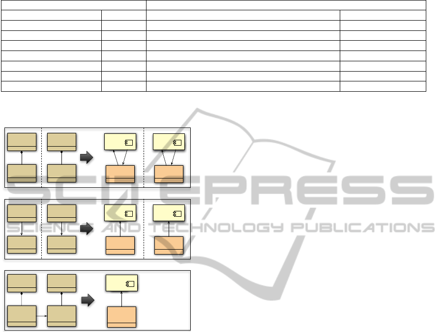
Table 4: Structural model: SysML to HLA element mapping.
SysML HLA
Element (Stereotype) Diagram Element (Stereotype Diagram
Block (Federate) BDD Component (Federate) Component Diagram
Block (ObjectClass) BDD Class (ObjectClass) Component Diagram
Block (Interaction Class) BDD Class (Interaction Class) Component Diagram
Attribute BDD Attribute (objectParameter or interactionParameter) Component Diagram
Class BDD Class (hlaService) Component Diagram
Operation BDD Operation (hlaMethod) Component Diagram
Attribute CDD Attribute (hlaDimension) Component Diagram
Struttura statica
«federate»
ClassA
«publish»«subscribe»
«federate»
«block»
ClassA
«federate»
«block»
ClassC
«objectClass»
«block»
ClassB
«interactionClass»«bl
ock»
ClassD
«objectClass»
ClassB
«federate»
ClassC
«publish»«subscribe»
«interactionClass»
ClassD
«federate»«block»
ClassC
«federate»«block»
ClassD
«objectClass»
(or«interactionClass»)
«block»
ClassA
«objectClass»
(or«interactionClass»)
«block»
ClassB
«federate»
ClassC
«subscribe»
«objectClass»
(or«interactionClass»)
ClassB
«federate»
ClassA
«subscribe»
«federate»
«block»
ClassA
«federate»
«block»
ClassC
«objectClass»
«block»
ClassB
«interactionClass»
«block»
ClassD
«objectClass»
ClassB
«federate»
ClassC
«subscribe»
«interactionClass»
ClassD
Rule 2
Rule 3
Rule 4
Figure 5: P/S Diagram generation rules.
The implementation of the proposed transforma-
tion includes the following templates:
• generateFederate: for each element in the HLA
model stereotyped as <<federate>>, generates
a java class that implements the corresponding
federate;
• generateObjIntClass: for each UML class in the
HLA model stereotyped as <objectClass>> or
<<interactionClass>>, generates a tag in the
XML file in which classes representing object-
Class and interactionClass are serialized. In other
words, such file constitutes the representation of
the FOM (Federate Object Model). Moreover,
this template creates, in each class generated by
the generateFederate template, the method for
publishing and subscribing resources, according
to the P/S diagram of the HLA model.
• generateAmbassador: generates a set of java
classes constituting the implementation of the
required federate ambassadors.
6 EXAMPLE APPLICATION
This Section presents an example application that
shows how the proposed model-driven method
effectively exploits the UML profiles discussed in
sections 3.1 and 4.1, in order to support the simulation
of a system by generating the HLA/Java code, starting
from its SysML specification.
The proposed example application deals with the
development of an automobile, in particular a Hybrid
gas/electric powered Sport Utility Vehicle (SUV)
(OMG, 2010).
6.1 System Specification
The first step of the method discussed in Section 5
includes the definition of the system model by use
of the SysML notation. For the sake of brevity,
this example only takes into account the diagrams
needed to derive the HLA simulation model and,
consequently, the code of the simulation program.
Specifically, the SysML automobile model includes
the following diagrams:
• Block definition diagram, to specify the structural
view of the system. The diagram shows the
automobile components (e.g., Vehicle, Brak-
ingSystem, Chassis e and Power Control Unit)
and their relationship;
• A set of sequence diagrams, to specify the behav-
ioral view of the system. Such diagrams describe
the interactions between system components.
6.2 Federation Specification
At the second step, the SysML model is refined
and annotated with stereotypes provided by the
HLAprofile. This step, that constitutes a PIM
marking, adds to the SysML model the information
needed to map each SysML domain element to the
corresponding HLA domain element and makes the
PIM model ready to be automatically processed by
AModel-drivenApproachtoBuildHLA-basedDistributedSimulationsfromSysMLModels
57
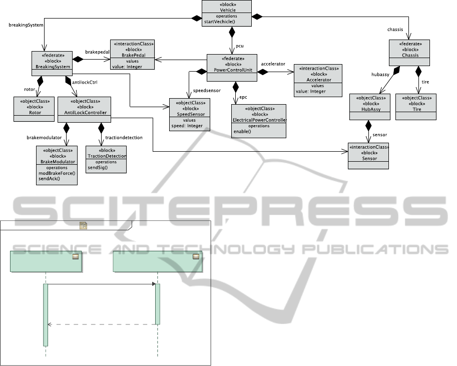
Figure 6: Source model: block definition diagram.
MagicDraw UML, 1-1 C:\Documents and Settings\paolo.bocciarelli\workspace\Vehicle\model.mdzip power Control Unit 24-feb-2012 10.37.10
power Control Unit power Control Unit[Interaction] sd [ ]
«objectClass»
«block»
epc : Elettrical Power Controller
«federate»
«block»
pcu : Power Control Unit
ready2:
enable()1:
Figure 7: Source model: sequence diagram
(interaction betwenn PowerControlUnit and
ElectricalPowerController).
the model-driven transformations included in the
next steps. As an example, figures 6 and 7 show
the BDD and a SD that specifies the interactions
between the PowerControlUnit component and the
ElectricalPowerController component, respec-
tively.
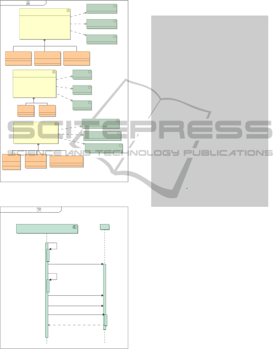
6.3 SysML-to-HLA transformation
The UML model annotated with SysML and HLA
profiles is given as input to the SysML-to-HLA
model-to-model transformation, to generate the HLA-
based simulation model. As discussed in Section
5.1, the HLA model is composed by a set of UML
sequence diagrams, and two UML component dia-
grams. The set of SDs specifies the behavioral view
of the HLA simulation model, the first component
diagram describes its structural view, while the other
one shows the publish/subscribe association among
federate, objectClass and interactionClass
HLA elements.
As an example, figures 8 and 9 depict the UML
component diagram showing the structural view and
the UML sequence diagram corresponding to the one
shown in Figure 7, respectively. For the sake of
readability, in such diagrams the adopted stereotype-
s/attributes have not been completely specified.
The component diagram in Figure 8 shows
the structure of the simulation model in terms of
federate objectClass and interactionClass
elements. The diagram also shows the interface
elements, stereotyped as hlaServices, that allow
each federate to communicate with RTI in order to
enact the interactions among federates.
6.4 HLA-to-code Transformation
At the last step of the method shown in Figure 5 the
HLA-to-code model-to-text transformation is carried
out. Such a transformation takes as input the HLA
model produced in the previous step and yields as
output the Java/HLA code which implements the
HLA-based distributed simulation. It should be
noted that the proposed method does not generate
the complete code that implements the HLA-based
distributed simulation. The model-driven method
should be considered as a supporting tool. More
specifically, the HLA-to-code transformation allows
to generate a template of the Java classes that contains
the class structure (i.e., constructor, method and
attribute declarations, exception management, etc.)
and most of the HLA-related code (i.e., data types
definition, RTI interaction methods, etc.), but the code
SIMULTECH2012-2ndInternationalConferenceonSimulationandModelingMethodologies,Technologiesand
Applications
58
MagicDraw UML, 1-1 C:\Documents and Settings\paolo.bocciarelli\workspace\Vehicle\SysML2HLA.mdzip SysML2HLA 15-mar-2012 15.54.10
SysML2HLAHLA Modelpackage [ ]
«federate»
BrakingSystem
«federate»
Power Control Unit
«federate»
Chassis
«hlaService»
ISpeedSensor
«hlaService»
IPower Control Unit
«hlaService»
IElettrical Power Controller
«objectClass»
Elettrical Power Controller
«hlaService»
IBrakingSystem
«hlaService»
IRotor
«hlaService»
IAnti-Lock Controller
«objectClass»
Rotor
«objectClass»
Anti-Lock Controller
-value : Integer
«interactionClass»
BrakePedal
-value : Integer
«interactionClass»
Accelerator
«hlaService»
ITire
«hlaService»
IHubAssy
«hlaService»
IChassis
-speed : Integer
«objectClass»
SpeedSensor
«objectClass»
Tire
«objectClass»
HubAssy
Figure 8: Target model: structural view.
MagicDraw UML, 1-1 C:\Documents and Settings\paolo.bocciarelli\workspace\Vehicle\SysML2HLA.mdzip PCU_behavior 13-mar-2012 17.16.51
PCU_behavior PCU_behaviorinteraction [ ]
«federate»
Power Control unit : Power Control Unit
RTI
createRTIAmbassador1:
«initialization»
createFederateExecution2:
«initialization»
createFederateAmbassador3:
«initialization»
enableTimeRegulation4:
«initialization»
joinFederation5:
«initialization»
enable6:
«action»
«message»
ready7:
Figure 9: Target model: sequence diagram (interaction
betwenn PowerControlUnit federate and RTI).
implementing the federate simulation logic has to be
added manually.
1
2 i m p o r t h l a . r t i 1 5 1 6 . ∗ ;
3 . . .
4 i m p o r t o r g . p o r t i c o . i m p l . h l a 1 5 1 6 . t y p e s . Do u bleTime ;
5
6 p u b l i c c l a s s Br a k i n g S y s t e m {
7 . . .
8 p u b l i c v o i d r u n F e d e r a t e ( ) {
9 / / c r e a t e t h e R TI a mb a s s a d or
10 r t i a m b = R t i F a c t o r y F a c t o r y . g e t R t i F a c t o r y ( ) .
g e t R t i A m b a s s a d o r ( ) ;
11 / / c r e a t e t h e f e d e r a t i o n
12 t r y {
13 F i l e fom = new F i l e ( " F OM . x ml " ) ;
14 r t i a m b . c r e a t e F e d e r a t i o n E x e c u t i o n ( "
Ex a m p l e Fe d e r a t i o n " ,
15 fom . toURI ( ) . toURL ( ) ) ;
16 lo g ( " C r ea t e d Fe d er a t io n " ) ;
17 }
18 ca t c h ( F e d e r a t i o n E x e c u t i o n A l r e a d y E x i s t s e x i s t s )
19 {
20 lo g ( " D id n ’t cr ea t e f e de r at i on , i t a lr e a dy
ex i s te d " ) ;
21 }
22 ca t c h ( MalformedURLExcept i o n e ) {
23 lo g ( " M a l fo r m e d U rl " ) ;
24 }
25 / / c r e a t e t h e f e d e r a t e am b a s s a d o r
26 fe d a mb = new B r a ki n g S y s te m A m ba s s a d o r ( ) ;
27 t h i s . f e d e r a t e N a m e = " B r a k in g S y s te m " ;
28 / / j o i n t h e f e d e r a t i o n
29 r t i a m b . j o i n F e d e r a t i o n E x e c u t i o n ( f e d e r a t e N a m e , "
Ex a m p l e Fe d e r a t i o n " ,
30 fedamb , n u l l ) ;
31 l o g ( " J o in e d F e d e ra t i o n as " + fe d e r a t e N a m e ) ;
32 / ∗ ∗∗∗∗ ∗ ∗ ∗∗∗∗∗∗ ∗ ∗∗∗∗∗∗∗ ∗ ∗∗∗∗∗∗∗ ∗ ∗∗∗∗
33 ∗ p l a c e h e r e s i m u l a t i o n l o g i c
34 ∗∗∗∗∗ ∗ ∗∗∗∗∗∗ ∗ ∗ ∗∗∗∗∗∗∗ ∗ ∗∗∗∗∗∗ ∗ ∗ ∗∗∗ ∗ /
35 / / r e s i g n f r om t h e f e d e r a t i o n
36 r t i a m b . r e s i g n F e d e r a t i o n E x e c u t i o n ( R e s i g n A c t i o n .
DELETE OBJECTS ) ;
37 l o g ( " R e si g n ed fr o m F e d e ra t i o n " ) ;
38 . . .
39 }
40 }
Listing 1: Java/HLA code generated by HLA-to-code
model-to-text transformation (portion).
As an example, a portion of the code that
implements the BrakingSystem federate is shown
in Listing 1. A comment acts as placeholder to
indicate where the code that implements the federate
simulation logic has to be placed.
7 CONCLUSIONS
This paper has introduced a model-driven approach
to support the code generation of a HLA-based
simulation from a SysML specification of the system
to be simulated. The approach has introduced two
different UML profiles. The first one, named HLA
profile, is used to annotate an UML diagram in
order to represent HLA-based details. The second
one, named SysML4HLA profile, is used to annotate
a SysML-based system specification to support the
subsequent automated generation of the HLA-based
distributed simulation code. The proposed approach
is founded on two transformations that automatically
map the source SysML model into a HLA-specific
AModel-drivenApproachtoBuildHLA-basedDistributedSimulationsfromSysMLModels
59

model and eventually into the Java/HLA source code,
as illustrated by an example case study dealing with
the automotive domain.
REFERENCES
D’Ambrogio, A., Iazeolla, G., and Gianni, D. (2011a).
A software architecture to ease the development
of distributed simulation systems. Simulation,
87(9):813–836.
D’Ambrogio, A., Iazeolla, G., Pieroni, A., and Gianni,
D. (2011b). A model transformation approach for
the development of hla-based distributed simulation
systems. In Proceedings of 1st International Con-
ference on Simulation and Modeling Methodologies,
Technologies and Applications (Simultech 2011),
pages 155–160.
Eclipse (2010). Eclipse Foundation, QVT Transformation
Engine. http://www.eclipse.org/m2m.
Eclipse (2011). Eclipse Foundation, Acceleo.
http://www.acceleo.org/pages/home/en.
Fujimoto, R. M. (1999). Parallel and Distribution
Simulation Systems. John Wiley & Sons, Inc., New
York, NY, USA, 1st edition.
Fujimoto, R. M. (2001). Parallel simulation: parallel
and distributed simulation systems. In Proceedings
of the 33nd conference on Winter simulation, WSC
’01, pages 147–157, Washington, DC, USA. IEEE
Computer Society.
Haouzi, H. E. (2006). Models simulation and interoperabil-
ity using mda and hla. In Proceedings of the IFAC/I-
FIP International conference on Interoperability for
Enterprise Applications and Software (I-ESA’2006).
IEEE (2000a). Recommended Practice for High Level
Architecture Federation Development and Execution
Process (FEDEP). IEEE Std. 1516.3-2003.
IEEE (2000b). Standard for Modeling and Simulation
(M&S) High Level Architecture (HLA) - frameworks
and rules. IEEE Std. 1516-2000.
IEEE (2000c). Standard for Modeling and Simulation
(M&S) High Level Architecture (HLA) - Object
Model Template (OMT) Specification. IEEE Std.
1516-2000.
IEEE (2000d). Standard for Modeling and Simulation
(M&S) High Level Architecture (HLA)- Federate
Interface Specification. IEEE Std. 1516.1-2000.
IEEE (2007). Recommended practice for High Level
Architecture (HLA) verification, validation and ac-
creditation (VV&A) of a federation-an overlay to the
High Level Architecture Federation Development and
Execution Process. IEEE Std. 1516.4-2007.
IKV++ (2008). Medini QVT. IKV++ Technologies Ag.
http://projects.ikv.de/qvt.
Jimenez, P., Galan, S., and Gariia, D. (2006). Spanish hla
abstraction layer: towards a higher interoperability
model for national. In Proceedings of the European
Simulation Interoperability Workshop.
Kuhl, F., Weatherly, R., and Dahmann, J. (1999). Creating
computer simulation systems: an introduction to the
high level architecture. Prentice Hall PTR, Upper
Saddle River, NJ, USA.
OMG (2003). MDA Guide, v. 1.0.1.
OMG (2008a). Meta Object Facility (MOF) 2.0
Query/View/Transformation, version 1.0.
OMG (2008b). MOF Model to Text Transformation
Language (MOFM2T), 1.0.
OMG (2010). System modeling language, v.1.2.
http://www.omg.org/spec/SysML/1.2/.
Paredis, C. J. J. and Johnson, T. (2008). Using omg’s sysml
to support simulation. In Proceedings of the 40th
Conference on Winter Simulation, WSC ’08, pages
2350–2352. Winter Simulation Conference.
Peak, R. S., Burkhart, R. M., Friedenthal, S. A., Wilson,
M. W., Bajaj, M., and Kim1, I. (2007). Simulation-
based design using sysmlpart 1: A parametrics primer.
In Proceedings of the INCOSE Intl. Symposium, San
Diego.
Portico (2010). Portico Project.
http://www.porticoproject.org/.
Tolk, A. and Muguira, J. A. (2004). M&s within
the model driven architecture. In Proceedings of
the Interservice/Industry Training, Simulation, and
Education (I/ITSEC) Conference.
Topc¸u, O., Adak, M., and O
ˇ
guzt
¨
uz
¨
un, H. (2008). A
metamodel for federation architectures. ACM Trans.
Model. Comput. Simul., 18:10:1–10:29.
Topc¸u, O. and O
ˇ
guzt
¨
uz
¨
un, H. (2000). Towards a uml
extension for hla federation design. In Conference on
Simulation Methods and Applications (CSMA 2000),
pages 204–213, Orlando, Florida USA.
Topc¸u, O., O
ˇ
guzt
¨
uz
¨
un, H., and Gerald, H. M. (2003).
Towards a uml profile for hla federation design, part ii.
In Proceedings of the Summer Computer Simulation
Conference (SCSC’03), pages 874–879, Montreal,
Canada.
Weyprecht, P. and Rose, O. (2011). Model-driven
development of simulation solution based on sysml
starting with the simulation core. In Proceedings
of the 2011 Symposium on Theory of Modeling
& Simulation: DEVS Integrative M&S Symposium,
TMS-DEVS ’11, pages 189–192, San Diego, CA,
USA. Society for Computer Simulation International.
Zhu, H., Li, G., and Zheng, L. (2008). A uml profile for hla-
based simulation system modeling. In Proceedings of
the 6th IEEE International Conference on Industrial
Informatics, INDIN 2008, Daejeon, Korea.
SIMULTECH2012-2ndInternationalConferenceonSimulationandModelingMethodologies,Technologiesand
Applications
60
